Abstract
Purpose.
To investigate the anatomy of the temporal raphe and its angular relationship to the optic disc and fovea in the human retina in vivo.
Methods.
Adaptive optics scanning laser ophthalmoscope (AOSLO) was used to image the temporal raphe in 11 young subjects. The raphe's angle relative to a horizontal line and the raphe-fovea-disc angle (angle between the raphe and the line connecting the disc and fovea center) were determined. In addition, to investigate the impact of aging on the raphe, we imaged the raphe at 9° eccentricity in 10 additional older healthy subjects and compared the raphe's anatomy between the two age groups.
Results.
The raphe's in vivo appearance was generally in agreement with major findings of ex vivo studies. The raphe angle was −1.67° ± 4.8°, with the ranges from −9° to 6°. It was related to the angle of the foveal depression relative to the disc. The raphe-fovea-disc angle was 170.3° ± 3.6°. The raphe gap, defined as the averaged distance between superior and inferior bundles, was significantly larger in the older subjects than in younger subjects (230.83 ± 113.22 μm vs. 1.93 ± 68.73 μm, P < 0.0001).
Conclusions.
The angle of the raphe in the study was not consistent with classic raphe models. While the angle showed relatively large individual variability, there seems to be a systematic relation between the disc, fovea, and raphe. It may be useful for individualizing retinal measurement strategies with regard to perimetry.
Keywords: raphe, adaptive optics, nerve fiber layer, foveal depression
The raphes' in vivo appearance were generally in agreement with major findings of ex vivo studies. While the range of raphe angles was large, the raphe angle is related to the angle of the foveal depression, and this may be useful for individualizing retinal measurement strategies.
Introduction
The temporal raphe is generally described as a horizontal boundary separating the superior and inferior retinal nerve fiber bundles in the temporal retina. Detailed anatomy of the temporal raphe in the human retina is mainly based on observations of enucleated eyes.1,2 However, these anatomic descriptions have never been validated by in vivo observations, and these early anatomic studies did not address the angular relationship of the temporal raphe to the fovea and disc.
In vivo details of the spatial properties of the temporal raphe are fundamental in interpreting glaucomatous visual field defects and their relation to structural changes measured at the optic disc. For instance, the nerve fiber bundles in the area of the temporal raphe are frequently affected in early glaucoma. Studies have shown that a nasal step, which is characterized by a vertically asymmetric visual function loss across the temporal raphe, is a major visual field defect in early glaucoma.3–6 In addition, a recent study showed that the geometric relation of the raphe to the optic disc and fovea is variable,7 and this variability can further complicate the work of modeling the trajectory of nerve fiber bundles and constructing structure-function maps for glaucoma diagnosis and management on an individual level.8–13
Unfortunately, only a few in vivo imaging techniques will allow adequate visualization of the nerve fiber bundles defining the temporal raphe. Traditional optical imaging methods such as fundus photography cannot image the temporal raphe due to resolution and contrast limitations. Optical coherence tomography (OCT) can provide high axial resolution in vivo14 and has been widely used to measure the thickness of retinal sublayers, especially the retinal nerve fiber layer (RNFL) thickness.15 However, the thickness of the RNFL at the raphe has been shown to be less than 30 μm,7,16 which is equivalent to only a few pixels in OCT images acquired by commercial OCT imaging systems. Therefore, the accuracy of using an RNFL thickness map to determine en face morphology of the raphe is limited.
Adaptive optics scanning laser ophthalmoscopy (AOSLO) allows high-resolution imaging of the en face plane by correcting ocular aberrations in real time.17 It has been widely used for retinal imaging, for instance, imaging of photoreceptors,18–20 blood flow,21–24 and nerve fiber bundles.25–28 In one recent study, AOSLO imaging demonstrated the ability to image the RNFL near the raphe.27
In the current study, we used AOSLO imaging to image the RNFL at the temporal raphe in 11 healthy eyes of 11 young subjects. For each subject, the temporal raphe was imaged from the temporal parafovea to at least 15° temporal to the fovea. The morphology of the raphe and its angular relationship to the optic disc and fovea were analyzed. In addition, to investigate the impact of aging on the RNFL in this region, we imaged the raphe at the 9° eccentricity in an additional set of 10 older subjects and compared the results between the two age groups.
Materials and Methods
Subjects
We tested 11 healthy young subjects (group 1: mean age 25 years old, SD 6.7 years, five men and six women) and 10 healthy older subjects (group 2: mean age 66.3 years old, SD 6.8 years, five men and five women). Each subject was examined by an ophthalmologist at least once in the past 12 months and found to be free of ocular disease or diabetes. Only one eye of each subject was studied. All studied eyes were dilated using 0.5% tropicamide. Each subject signed an approved consent form after the individual received a full explanation of the procedures and consequences of this study. The study protocol was approved by the Indiana University Institutional Review Board, and the research is in compliance with the Declaration of Helsinki.
The Indiana Adaptive Optics Scanning Laser Ophthalmoscope
The wide-field AOSLO developed at the Indiana University Bloomington has been presented previously.29 In brief, the AOSLO uses wavelengths of 820 to 840 nm for retinal imaging. The system is capable of correcting ocular aberrations in real time by employing a woofer-tweeter dual deformable-mirror closed-loop system. The imaging field size is programmable, ranging from approximately 1° by 1° to 3° by 3°. Either field size is much smaller than imaging field sizes of regular fundus cameras. This difference is because the imaging field size for adaptive optics (AO) imaging is limited by the isoplanatic angle in human eyes.30,31 The fixation targets for subjects are optically projected to the retina by a custom digital projector incorporated within the AOSLO.
Procedures
Imaging for the Young Subjects (Group 1)
Each subject participated in three imaging stages sequentially during a single session lasting a total of approximately 80 minutes. In the first stage, we measured the axial length of each studied eye using a biometer (IOL Master; Carl Zeiss Meditec, Dublin, CA, USA). In the second stage, we imaged each studied eye using a scanning laser ophthalmoscope/optical coherence tomography (SLO/OCT) system (Spectralis; Heidelberg Engineering, Heidelberg, Germany). For the SLO imaging, we acquired three wide-field SLO images in sequence, with the field centered on the fovea and approximately 12° nasally and temporally. The field size for each SLO image was set as 30° by 30°. After image acquisition, these three images were stitched into a mosaic using the Heidelberg's built-in software. We also performed two orthogonal OCT volume scans centered at the fovea. Each scan had a scanning size of 15° by 5°, with longer dimension placed along the OCT B-scans' direction. Adjacent OCT A-scans in each volume scan were 30 μm apart.
In the third stage, we imaged the temporal raphe of each studied eye using the AOSLO. The imaging field of the AOSLO was set as 3° by 3°, which was adequate for detecting the details of the RNFL as was determined in pilot studies. We started the imaging just temporal to the fovea where nerve fiber bundles can be first detected by the AOSLO. After imaging bundles in this region, we repositioned the imaging field to the next location that was temporal to the current position, with 0.5° or more of overlap between imaging locations. Images were recorded in the new location. This process was repeated until we reached at least 15° temporal to the fovea. In each step, we needed to adjust the imaging location slightly to ensure that the raphe appeared within the field of view of the images. For each location, the optical beam of the AOSLO was focused on the RNFL, and 75 images (approximately 2.3 seconds) were recorded. During the session, the subject's pupil was maintained in alignment with the AOSLO system by adjusting the position of a motorized chin rest. The subject was given breaks every 5 to 10 minutes. The whole AOSLO session for each subject took between 30 and 45 minutes.
Imaging for the Older Subjects (Group 2)
We simplified the imaging protocol for the older subjects to further shorten the testing time. For each studied eye, we measured the axial length using a biometer (IOL Master; Carl Zeiss Meditec). We performed AOSLO imaging of the raphe only between 8° to 10° eccentricities, with the same imaging field size and step size as for the young subjects.
Processing of AOSLO Images and Formation of Montages
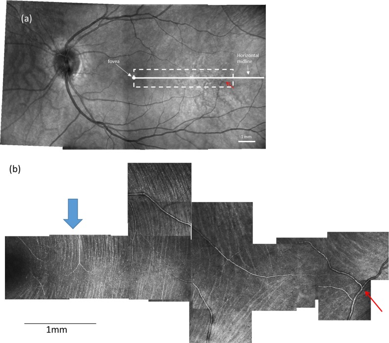
Following imaging, we processed raw AOSLO videos to align individual images and generate average images at each location.32 We then manually constructed a montage for each eye using image-analysis software (Photoshop CS6; Adobe Systems, San Jose, CA, USA), as described below. First, AOSLO images from the same retina were aligned to each other based on overlapping portions of spatially adjacent images. Second, the montage was aligned into the wide-field SLO mosaic. Figure 1a shows a wide-field SLO mosaic, and Figure 1b shows an AOSLO montage. The red arrow in Figures 1a and b points to the same blood vessel to allow comparison of the relative positions.
Figure 1.
A wide-field fundus mosaic and an AOSLO raphe montage from the same subject in group 1. (a) Fundus mosaic composed from three 30°-by-30° Spectralis SLO images. The solid white circle represents the fovea as determined from OCT scans (see text). The white dashed box indicates the approximate region of AOSLO imaging. For all subjects, the AOSLO image was at least 15° in horizontal extent. The white solid line indicates the horizontal midline. (b) Raphe montage constructed from a series of AOSLO images. Contrast and brightness of each image has been adjusted to maximize the visibility of bundles and to approximately balance intensities. The blue arrows in (b) indicate the regions that are enlarged in Figure 2. The red arrow in (a) and (b) point to the same blood vessel to allow comparison of the relative positions. Scale bars: 1 mm on both images.
Image Analysis
Analysis of Images of the Young Subjects (Group 1)
Measurement of the Raphe's Gaps and Locations in AOSLO Montages.
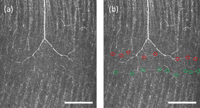
The nerve fiber bundles become thin and undetectable near the raphe. To quantify the size and location of this region without detectable nerve fiber bundles, we first manually marked the ends of the detectable nerve fiber bundles that were closest to the raphe for both the superior and inferior nerve fiber bundles. Next, for each side of the raphe, we used a linear model to interpolate positions of the bundle boundary between every two adjacent bundle tips that were marked in the first step, generating a continuous boundary for the bundles on the superior and inferior side of the raphe. Figure 2 shows examples of these measurements.
Figure 2.
Enlargement of an AOSLO image from Figure 1b demonstrating the method for raphe location determination. The raphe is approximately 1 mm from the fovea. (a) An image cropped from the montage in Figure 1b. (b) The figure shows boundaries for inferior bundles (green circles) and superior bundles (red circles). The raphe location is computed as the mean position between the two boundaries. This subject has a positive raphe gap at this eccentricity. Scale bar: 200 μm.
The superior and inferior boundaries were used to compute the raphe's gaps and locations. The gap was measured as the vertical distance between the two boundaries as a function of retinal eccentricity. Note that if the superior and inferior bundles interleave, the raphe gap becomes negative. The raphe position was computed as the average of the positions of the superior and inferior bundle boundaries for every retinal eccentricity. These raphe positions were further used to define a straight raphe line using a least squares fit for the computation of the raphe's angle in the next step.
Measurement of Raphe's Position relative to the Optic Disc.
Determination of Fovea Center.
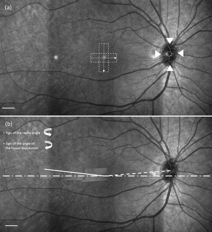
The fovea location was identified on each SLO montage using data from the OCT volume scans. The fovea region of each studied eye had been scanned with two OCT volume scans that were orthogonal to each other. In each pair of volume scans, we picked out the OCT B-scan image that was across or closest to the foveal pit. Its corresponding location on the SLO image was automatically identified as a line by the Heidelberg's built-in software. Thus, the crossing point of the two orthogonal lines was selected as the foveal center on the wide-field SLO mosaic, as shown in Figure 3a.
Figure 3.
Example of the angular relation between the raphe, fovea, and optic disc. (a) Determination of the fovea and optic disc center. Dashed boxes in the center represent locations of OCT volume scans used to locate the center of the foveal pit. The arrows represent the orientations of B-scans. The arrowheads around the optic disc identify the upper, lower, left, and right boundaries of the optic disc. The dashed circle is taken as the center (see text). Scale bar: 1 mm. (b) The dotted line connects the center of the optic disc and fovea. The dashed line represents the horizontal midline across the fovea. The solid line is the raphe determined from the AO montage and represents the least square linear fit to the measurements. Details of identifying the raphe and its angle are described in the text. Scale bar: 1 mm.
Determination of the Optic Disc Center and Its Angle.
The center of the optic disc was marked on each SLO montage by the following steps. First, we manually marked the four disc margins on the nasal, temporal, superior, and inferior sides. Second, we averaged the vertical positions of the inferior and superior margins and the horizontal positions of the temporal and nasal margins. The averaged results were used as the position of the optic disc center, as shown in Figure 3a. The angle of foveal depression was then computed using the positions of the fovea and optic disc center, as shown in Figure 3b.
Determination of the Raphe's Angle and Its Angular Relation to the Optic Disc.
We used the fitted raphe line described above to compute the raphe's angle relative to the horizontal midline of the retina. Sample results are presented in Figure 3b. We then computed the angle between the raphe and the line that connects the disc center and fovea and defined this angle as the raphe-fovea-disc angle.
Analysis of the Effect of Aging
For the older subjects (group 2), only the raphe gap was measured. The raphe's positions and angle were not measured for this group to avoid measurement errors due to the smaller imaging extent (between 8° and 10° eccentricities).
To analyze the aging effect, the raphe gaps between 8° and 10° eccentricity for each subject of the study were averaged and compared between the two groups. An unpaired t-test was used to test for statistical differences between the averaged gaps of the younger and older subjects.
Results
Appearance of the Raphe and Nerve Fiber Bundles in Eyes of the Young Subjects (Group 1)
Nerve fiber bundles were observed on both the superior and inferior temporal retina for all subjects tested. The bundles appeared as reflective strips with intervening dark strips (Fig. 1b). As the bundles from the superior and inferior retina approach each other in the temporal retina, they become thinner and the raphe is formed.
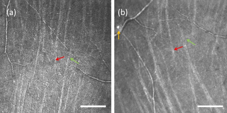
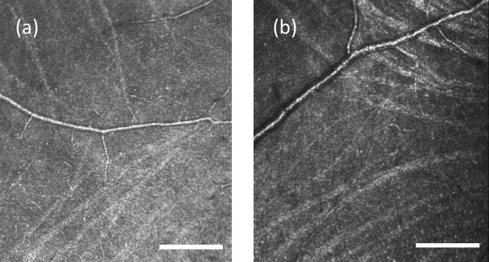
The appearance of the raphe changed with eccentricity. For all subjects' locations that were within approximately 3° to 5° temporal to the fovea, the bundles from the superior and inferior sides were narrow and ceased to be visible before they met; therefore, the raphe appeared as a relatively dark band. The directions of bundles were approximately perpendicular to the raphe in this area, as shown in Figure 2a. In locations that were slightly farther from the fovea, we observed that bundles' directions gradually became somewhat oblique relative to the vertical orientation seen closer to the fovea. In three young subjects, we observed that bundles in this region extended to the opposite side such that the inferior and superior bundles were interleaved, as shown in Figure 4. For the other eight young subjects, interleaving was not observed. In all cases the approach defined above (in the discussion of the measurement of the raphe's gaps) determined the raphe location. At large eccentricities the bundles formed a quasi-triangular pattern, as shown in Figures 1 and 5. In the region temporal to the triangular zone, the superior and inferior bundles gradually became more horizontal and parallel to each other. Here the raphe can be described as a narrow zone between relatively horizontal bundles that travel to the superior and inferior portions of the disc. In older subjects the raphe was wider, and bundle interleaving was not detectable in any of the subjects. The other features observed in young subjects cannot be commented on as they were not included in the imaged area.
Figure 4.
An example of a raphe with intermingling bundles from two group 1 subjects. (a) The location is approximately 2 mm relative to the fovea. (b) The location is approximately 2.8 mm temporal to the fovea. Scale bar: 200 μm. The red and green arrows point to examples of bundles that interdigitate. Occasional reflective cells along vessels can be observed, as shown by the yellow arrow in (b).
Figure 5.
Raphe with oblique bundles forming a triangle bundle pattern. Images are from two subjects in group 1. (a) A region approximately 3.7 mm from the fovea in a 26-year-old female. (b) A region approximately 3.8 mm from the fovea in a 26-year-old female. Scale bar: 200 μm.
In addition to nerve fiber bundles, we also observed non-RNFL elements. Blood vessels were seen throughout the temporal retina as expected. Some crossed the raphe, even in locations that are close to the fovea. We measured the crossing location of the vessel closest to the fovea for each subject. The locations ranged from 2.6° to 14.3°, with an average at 6.4°. In addition, we often observed patches of highly reflective structures in this part of the retina. They often appeared in peripheral retina beyond approximately 10°, located near vessels, and did not show any evidence of distorting the surrounding retina. One example of these structures can be seen in Figure 4b; however, many were detected.
The Raphe Angle and Its Relation to the Optic Disc
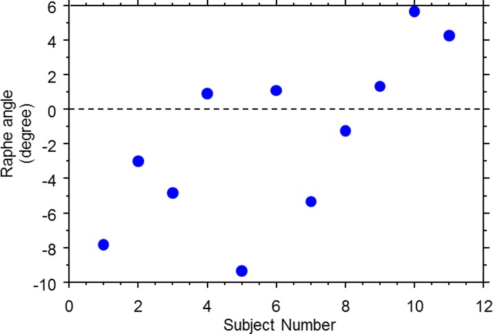
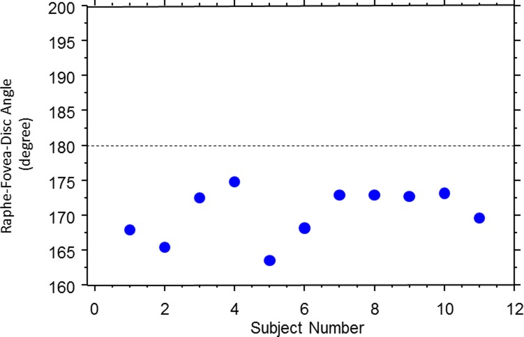
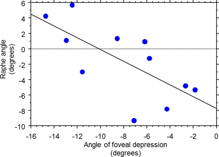
On average, the raphe angle was −1.67° ± 4.8° relative to a horizontal line, with a range of angles from −9° to +6°, as shown in Figure 6. The raphe-fovea-optic angle was 170.3° ± 3.6°, as shown in Figure 7. The angle of the raphe was related to the angle of the foveal depression. A linear regression shows the slope was −0.766 ± 0.604 (P = 0.0185), as shown in Figure 8. As the angle of the foveal depression increased, such that fovea was lower relative to the disc, the raphe was also rotated downward so the two rotate together.
Figure 6.
Raphe angles across the younger subjects (group 1).
Figure 7.
The raphe-fovea-disc angle in the younger subjects (group 1).
Figure 8.
Relation of the raphe angle to the angle of foveal depression in the younger subjects (group 1).
Aging Effect on the Raphe Gap
While the raphe gap was quite small or even nonexistent due to interleaving of the superior and inferior bundles in the young eyes, the gap increased in the older eyes, and interleaving of bundles was not observed in any of these older subjects. As a result, the averaged raphe gap at 9° eccentricity was significantly different between the two groups (group 1, 1.93 ± 68.73 μm; group 2, 230.83 ± 113.22 μm; P < 0.0001), as shown in Figure 9.
Figure 9.
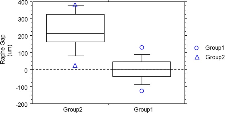
Box and whiskers plot for comparison of the raphe gap (defined in text) between the younger subjects (group 1) and older subjects (group 2). The averaged gap for each subject was computed by averaging the raphe gaps between 8° and 10° eccentricity. For each plot, the five horizontal lines represent 90%, 75%, 50%, 25%, and 10% of the population distribution, and the individual data points above the 90% or below the 10% are also plotted individually in the graph. The raphe gap in the two groups are significantly different (group 1: 1.93 ± 68.73 μm; group 2: 230.83 ± 113.22 μm; t-test, P < 0.0001).
Discussion
The purpose of this study was to explore the raphe's morphology in both younger and older healthy subjects. The in vivo images have shown that the raphe appearance can vary considerably with retinal eccentricity. The quantitative analysis suggests the raphe's geometry in the retina is neither strictly horizontal to the fovea nor to the optic disc. Instead, the lower the fovea is relative to the disc, the more downward the angle of the raphe, suggesting a new view of the raphe's geometry that could be important in the proper interpretation of visual fields.
The morphology of the raphe has been described in several independent ex vivo studies, although not all the reports were consistent with our findings.1,2 Some studies reported that the superior and inferior bundles stopped right at the raphe, while others reported that bundles could cross the raphe, as we found in some of our subjects. The interleaving of bundles observed in our study confirmed that there could frequently be some degree of overlap between projections to the superior and inferior regions of the disc. The overlap could cause some blurring of the visual field deficit across the raphe. That is, for a person with glaucomatous damage localized to either the superior or inferior areas of the disc, this raphe anatomy could lead to visual field loss that did not respect a “horizontal” meridian. In the older subjects, no such overlap of the superior and inferior bundles was visible. We interpret this as likely a consequence of the increased raphe gap, and we interpret the increased raphe gap as a consequence of both a decreased visibility of bundles with age and perhaps as a sign of the ongoing loss of ganglion cells with age (see below).
The dark-band raphe that we observed in the region close to the fovea in the young eyes suggests that bundles were smaller here than in regions that were farther away. While scatter or inadequate AO control could cause a failure to resolve these small fibers, this is unlikely because these eyes were young and we observed small bundles in nearby regions in the same eyes.
In all studies, including ours, a transitional area occurs where peripheral, radially oriented bundles begin to arc around the macula. Closer to the fovea than the transition area, ganglion cells will project their axons directly away from the raphe, with a course toward either the superior or inferior portion of the disc, with the probability of either projection depending on the location. Peripheral to the transition area, ganglion cells initially send axons approximately toward the disc, but those axons deviate from their radial traverse at the transition area and curve superiorly or inferiorly around the fovea.
Our data show that the raphe's appearance is affected by aging. The enlarged raphe gap in the older subjects is presumably occurring due to poor optics that we are not fully compensating (for instance, very high-frequency aberrations of the tear film), due to optical changes with age,33 or due to axonal loss with aging.34,35 Because we still see quite small bundles just displaced from the raphe center, we do not believe it is fully attributable to optical changes, although the well-known change in the retinal reflex with age supports a change in overall reflectivity. We also know that there are changing numbers of ganglion cells and axonal bundles with age. It is possible that the thinning of the RNFL seen with aging in OCT images36 is manifest here by reducing bundle sizes to the point that they are not visible and thus form a larger gap. This sort of phenomenon likely would be visible only in a retinal area in which there is a transition from no visible bundles to definitely visible bundles and would not be measured in areas of densely overlapping bundles such as near the vascular arcades. This change is most likely the locally visible evidence of a global loss of nerve fibers due to aging.
What remains unexplored in all ex vivo studies is the spatial relation of the raphe to other parts of the retina. Traditionally, there have been two theoretical frameworks relating the temporal raphe location to overall retinal structure. The first model assumes that the temporal raphe is lined up with the center of the optic disc. The second one assumes the temporal raphe is a horizontal line extending from the fovea. Both models have been used for various clinical applications. For example, the first model is used in the posterior pole asymmetry analysis, and the second model is used to interpret visual field defects in the nasal visual field.
However, each model is inconsistent with the results of our study. The first model is very unlikely to be correct based on the result in Figure 7, which shows that the total angle between the raphe and optic disc is on average 170° and never reaches 180° for any subject of this study. The second model is also unlikely to be correct as suggested by Figures 6 through 8. Although the averaged angle of the raphe among subjects is close to 0°, as shown in Figure 6, the individual variance across these subjects is relatively large. The angle in some individuals can reach more than 5° off the horizontal midline.
There are several sources possibly attributed to the large individual variance of the raphe angle. The first is the linkage between the raphe angle and foveal depression as suggested in Figure 8. The slope of the regression line for the relation between raphe and depression angles is much closer to the slope of 1 than to the slope of 0. This is unlikely to be caused by a bias in the measured foveal depression angles because they varied from −2° to −15° across individuals in our study, very similar to results of other studies.9,13,37,38 Other possible sources attributed to the raphe angle variance include subjects' head position and measurement errors of identifying the disc center, fovea, and raphe. Future studies are warranted to investigate the roles of these sources of variance on the raphe angle measurement.
Clinical Implications
The inconsistency of the data for the two raphe models discussed above suggests that there are clinical implications, since many measurements are based on these models. For example, glaucoma specialists use the horizontal raphe model to interpret results in the nasal field. However, for a subject who has an 8° raphe angle as shown for one of our subjects, the vertical deviation between the model and the subject's raphe can reach up to 2.8° when we look at field locations that are beyond 20° in the nasal field. This deviation is large enough that at least the two outermost nasal inferior locations of the 24-2 visual field should in fact be assigned to the opposite hemisphere for that subject. This could possibly explain some of the nasal steps that extend across the horizontal meridian. It is possible that they are not actually extending across the anatomic raphe in a particular patient.
Besides the visual field, there has been a trend of performing asymmetry analysis of the central macular thickness to evaluate glaucoma damage. The analysis uses the raphe as a retinal hemisphere boundary in the temporal retina and compares the thickness of the regions that are located symmetric to the raphe. Obviously, a choice of the wrong raphe model can cause incorrect pairing of regions and distort the asymmetry analysis.
We conclude that the raphe's geometry cannot be ignored, as it might be closely related to how the clinical data are analyzed and interpreted. With rapid developments of retinal imaging devices, the identification of the raphe for individual patients in clinics can be realistic. For instance, recent studies reported imaging the raphe with medium lateral resolution using OCT transverse images (Laura de Polo AI, et al. IOVS 2013; 45: ARVO E-Abstract 4815). Although the resolution of those images is not as good as the AOSLO images, the raphe geometry can be measured. These individual raphe images could enable personalized visual fields and asymmetry analysis in the near future.
Conclusions
The detailed in vivo morphology of the temporal raphe was shown in AOSLO images. These in vivo images were generally in agreement with major findings of ex vivo studies. Further quantitative analysis showed a relatively large individual range of the raphe angle and indicated its possible linkage to the angle of foveal depression. The angle between the raphe and the line that connects the fovea and disc center was, on average, 170°. These results were not consistent with the two classic raphe models: one that the raphe is horizontal and in line with the fovea and the other that the raphe is lined up with the optic disc. For clinical diagnostic instruments and approaches that use the raphe's geometry models, either a new model or an approach of getting a personalized raphe image may help to further improve understanding of the relation between visual field deficits and structural imaging.
Acknowledgments
The authors thank William H. Swanson, PhD, for helpful discussion, and Luo Ting, MS, for her comments on data analysis.
This work was supported by the National Institutes of Health (Bethesda, MD, USA) Grants R01 EY04395 and P30EY019008.
Disclosure: G. Huang, None; T.J. Gast, None; S.A. Burns, None
References
- 1. Ballantyne AJ. The nerve fiber pattern of the human retina. Tr Ophth Soc U Kingdom. 1947; 66: 179 [Google Scholar]
- 2. Vrabec F. The temporal raphe of the human retina. Am J Ophthalmol. 1966; 62: 926–938 [DOI] [PubMed] [Google Scholar]
- 3. Werner EB, Drance SM. Early visual field disturbances in glaucoma. Arch Ophthalmol. 1977; 95: 1173–1175 [DOI] [PubMed] [Google Scholar]
- 4. Armaly MF. Visual field defects in early open angle glaucoma. Trans Am Ophthalmol Soc. 1971; 69: 147–162 [PMC free article] [PubMed] [Google Scholar]
- 5. Hart WM Jr, Becker B. The onset and evolution of glaucomatous visual field defects. Ophthalmology. 1982; 89: 268–279 [DOI] [PubMed] [Google Scholar]
- 6. Lee AJ, Wang JJ, Rochtchina E, Healey P, Chia EM, Mitchell P. Patterns of glaucomatous visual field defects in an older population: the Blue Mountains Eye Study. Clin Experiment Ophthalmol. 2003; 31: 331–335 [DOI] [PubMed] [Google Scholar]
- 7. Hood DC, Raza AS, de Moraes CG, Liebmann JM, Ritch R. Glaucomatous damage of the macula. Prog Retin Eye Res. 2013; 32: 1–21 [DOI] [PMC free article] [PubMed] [Google Scholar]
- 8. Weber J, Ulrich H. A perimetric nerve fiber bundle map. Int Ophthalmol. 1991; 15: 193–200 [DOI] [PubMed] [Google Scholar]
- 9. Garway-Heath DF, Poinoosawmy D, Fitzke FW, Hitchings RA. Mapping the visual field to the optic disc in normal tension glaucoma eyes. Ophthalmology. 2000; 107: 1809–1815 [DOI] [PubMed] [Google Scholar]
- 10. Schiefer U, Flad M, Stumpp F, et al. Increased detection rate of glaucomatous visual field damage with locally condensed grids: a comparison between fundus-oriented perimetry and conventional visual field examination. Arch Ophthalmol. 2003; 121: 458–465 [DOI] [PubMed] [Google Scholar]
- 11. Jansonius NM, Nevalainen J, Selig B, et al. A mathematical description of nerve fiber bundle trajectories and their variability in the human retina. Vision Res. 2009; 49: 2157–2163 [DOI] [PMC free article] [PubMed] [Google Scholar]
- 12. Jansonius NM, Schiefer J, Nevalainen J, Paetzold J, Schiefer U. A mathematical model for describing the retinal nerve fiber bundle trajectories in the human eye: average course, variability, and influence of refraction, optic disc size and optic disc position. Exp Eye Res. 2012; 105: 70–78 [DOI] [PubMed] [Google Scholar]
- 13. Lamparter J, Russell RA, Zhu H, et al. The influence of intersubject variability in ocular anatomical variables on the mapping of retinal locations to the retinal nerve fiber layer and optic nerve head. Invest Ophthalmol Vis Sci. 2013; 54: 6074–6082 [DOI] [PubMed] [Google Scholar]
- 14. Huang D, Swanson EA, Lin CP, et al. Optical coherence tomography. Science. 1991; 254: 1178–1181 [DOI] [PMC free article] [PubMed] [Google Scholar]
- 15. Schuman JS, Hee MR, Puliafito CA, et al. Quantification of nerve fiber layer thickness in normal and glaucomatous eyes using optical coherence tomography. Arch Ophthalmol. 1995; 113: 586–596 [DOI] [PubMed] [Google Scholar]
- 16. Hood DC, Raza AS, de Moraes CG, Johnson CA, Liebmann JM, Ritch R. The nature of macular damage in glaucoma as revealed by averaging optical coherence tomography data. Trans Vis Sci Technol. 2012; 1: 3 [DOI] [PMC free article] [PubMed] [Google Scholar]
- 17. Roorda A, Romero-Borja F. Donnelly Iii W, Queener H, Hebert T, Campbell M. Adaptive optics scanning laser ophthalmoscopy. Opt Express. 2002; 10: 405–412 [DOI] [PubMed] [Google Scholar]
- 18. Chui TY, Song H, Burns SA. Adaptive-optics imaging of human cone photoreceptor distribution. J Opt Soc Am A Opt Image Sci Vis. 2008; 25: 3021–3029 [DOI] [PMC free article] [PubMed] [Google Scholar]
- 19. Merino D, Duncan JL, Tiruveedhula P, Roorda A. Observation of cone and rod photoreceptors in normal subjects and patients using a new generation adaptive optics scanning laser ophthalmoscope. Biom Opt Express. 2011; 2: 2189–2201 [DOI] [PMC free article] [PubMed] [Google Scholar]
- 20. Dubra A, Sulai Y. Reflective afocal broadband adaptive optics scanning ophthalmoscope. Biomed Opt Express. 2011; 2: 1757–1768 [DOI] [PMC free article] [PubMed] [Google Scholar]
- 21. Chui TY, Gast TJ, Burns SA. Imaging of vascular wall fine structure in the human retina using adaptive optics scanning laser ophthalmoscopy. Invest Ophthalmol Vis Sci. 2013; 54: 7115–7124 [DOI] [PMC free article] [PubMed] [Google Scholar]
- 22. Tam J, Tiruveedhula P, Roorda A. Characterization of single-file flow through human retinal parafoveal capillaries using an adaptive optics scanning laser ophthalmoscope. Biomed Opt Express. 2011; 2: 781–793 [DOI] [PMC free article] [PubMed] [Google Scholar]
- 23. Zhong Z, Song H, Chui TY, Petrig BL, Burns SA. Noninvasive measurements and analysis of blood velocity profiles in human retinal vessels. Invest Ophthalmol Vis Sci. 2011; 52: 4151–4157 [DOI] [PMC free article] [PubMed] [Google Scholar]
- 24. Zhong Z, Huang G, Chui TY, Petrig BL, Burns SA. Local flicker stimulation evokes local retinal blood velocity changes. J Vis. 2012; 12: 3 [DOI] [PMC free article] [PubMed] [Google Scholar]
- 25. Takayama K, Ooto S, Hangai M, et al. High-resolution imaging of the retinal nerve fiber layer in normal eyes using adaptive optics scanning laser ophthalmoscopy. PloS One. 2012; 7: e33158 [DOI] [PMC free article] [PubMed] [Google Scholar]
- 26. Takayama K, Ooto S, Hangai M, et al. High-resolution imaging of retinal nerve fiber bundles in glaucoma using adaptive optics scanning laser ophthalmoscopy. Am J Ophthalmol. 2013; 155: 870–881 [DOI] [PubMed] [Google Scholar]
- 27. Huang G, Qi X, Chui TY, Zhong Z, Burns SA. A clinical planning module for adaptive optics SLO imaging. Optom Vis Sci. 2012; 89: 593–601 [DOI] [PMC free article] [PubMed] [Google Scholar]
- 28. Kocaoglu OP, Cense B, Jonnal RS, et al. Imaging retinal nerve fiber bundles using optical coherence tomography with adaptive optics. Vis Res. 2011; 51: 1835–1844 [DOI] [PMC free article] [PubMed] [Google Scholar]
- 29. Ferguson RD, Zhong Z, Hammer DX, et al. Adaptive optics scanning laser ophthalmoscope with integrated wide-field retinal imaging and tracking. J Opt Soc Am A Opt Image Sci Vis. 2010; 27: A265–277 [DOI] [PMC free article] [PubMed] [Google Scholar]
- 30. Bedggood P, Daaboul M, Ashman R, Smith G, Metha A. Characteristics of the human isoplanatic patch and implications for adaptive optics retinal imaging. J Biomed Opt. 2008; 13: 024008 [DOI] [PubMed] [Google Scholar]
- 31. Nowakowski M, Sheehan M, Neal D, Goncharov AV. Investigation of the isoplanatic patch and wavefront aberration along the pupillary axis compared to the line of sight in the eye. Biomed Opt Express. 2012; 3: 240–258 [DOI] [PMC free article] [PubMed] [Google Scholar]
- 32. Song H, Chui TY, Zhong Z, Elsner AE, Burns SA. Variation of cone photoreceptor packing density with retinal eccentricity and age. Invest Ophthalmol Vis Sci. 2011; 52: 7376–7384 [DOI] [PMC free article] [PubMed] [Google Scholar]
- 33. McLellan JS, Marcos S, Burns SA. Age-related changes in monochromatic wave aberrations of the human eye. Invest Ophthalmol Vis Sci. 2001; 42: 1390–1395 [PubMed] [Google Scholar]
- 34. Gao H, Hollyfield JG. Aging of the human retina. Differential loss of neurons and retinal pigment epithelial cells. Invest Ophthalmol Vis Sci. 1992; 33: 1–17 [PubMed] [Google Scholar]
- 35. Curcio CA, Drucker DN. Retinal ganglion-cells in Alzheimers-disease and aging. Ann Neurol. 1993; 33: 248–257 [DOI] [PubMed] [Google Scholar]
- 36. Alasil T, Wang KD, Keane PA, et al. Analysis of normal retinal nerve fiber layer thickness by age, sex, and race using spectral domain optical coherence tomography. J Glaucoma. 2013; 22: 532–541 [DOI] [PubMed] [Google Scholar]
- 37. Choi JA, Kim JS, Park HY, Park H, Park CK. The foveal position relative to the optic disc and the retinal nerve fiber layer thickness profile in myopia. Invest Ophthal Vis Sci. 2014; 55: 1419–1426 [DOI] [PubMed] [Google Scholar]
- 38. Lefevre F, Leroy K, Delrieu B, Lassale D, Pechereau A. [Study of the optic nerve head-fovea angle with retinophotography in healthy patients]. J Fr Ophtalmol. 2007; 30: 598–606 [DOI] [PubMed] [Google Scholar]


