Abstract
The human elbow joint has been regarded as a loose hinge joint, with a unique helical motion of the axis during extension–flexion. This study was designed to identify the helical axis in the ulnohumeral joint during elbow extension–flexion by tracking the midpoint between the coronoid tip and the olecranon tip of the proximal ulna in a three-dimensional (3D) computed tomography (CT) image model. The elbows of four volunteers were CT-scanned at four flexion angles (0°, 45°, 90°, and 130°) at neutral rotation with a custom-made holding device to control any motion during scanning. Three-dimensional models of each elbow were reconstructed and a 3D ulnohumeral joint at 45°, 90°, and 130° was superimposed onto a fully extended joint (0°) by rotating and translating each 3D ulnohumeral joint along the axes. The midpoints of the olecranon and coronoid tips were interpolated using cubic spline technique and the dynamic elbow motion was plotted to determine the motion of the helical axis. The means and standard deviations were subsequently calculated. The average midpoint pattern of joint motion from extension to flexion was elliptical-orbit-like when projected onto a sagittal plane and continuously translated a mean 2.14 ± 0.34 mm (range, 1.83–2.52 mm) to the lateral side during elbow extension–flexion. In 3D space, the average midpoint pattern of the ulnohumeral joint resembles a vortical flow, spinning along an imaginary axis, with an inconsistent radius from 0° to 130° flexion. The ulnohumeral joint axis both rotates and translates during elbow extension–flexion, with a vortex-flow motion occurring during flexion in 3D model analysis. This motion should be considered when performing hinged external fixation, total elbow replacement and medial collateral ligament reconstruction surgery.
Keywords: three-dimensional, computer-aided design, ulnohumeral, vortex-flow motion
Introduction
The human elbow joint has been considered a simple hinge joint (Byram et al. 2013), having a single degree-of-freedom movement with a fixed linear axis. Recent studies, however, have shown that the human elbow is a loose hinge joint, with a unique helical motion of its axis during extension–flexion (Morrey & Chao, 1976; Bottlang et al. 2000; Duck et al. 2003; Goto et al. 2004; Bryce & Armstrong, 2008; Morrey & Sanchez-Sotelo, 2008; Miyake et al. 2012). This helical axis has been assessed using various techniques, and the center of rotation of the elbow was found to be located in the medial aspect of the trochlea in the distal humerus (Bottlang et al. 2000; Duck et al. 2003; Bryce & Armstrong, 2008; Morrey & Sanchez-Sotelo, 2008). Those studies, however, found different patterns of helical motion of the ulnohumeral axis during extension–flexion.
Using Reuleaux's technique, the instant center of rotation was found to be located at the center of the trochlea (Fischer, 1911), a finding confirmed using a biplanar x-ray method (Morrey & Chao, 1976; Morrey & Sanchez-Sotelo, 2008). Use of the Flock of Birds electromagnetic tracking system to analyze cadaveric human elbow joints in passive motion showed a roller configuration pathway of the screw displacement axis during elbow flexion (Bottlang et al. 2000; Madey et al. 2000). Recently, the screw axis of the elbow joint was calculated by three-dimensional (3D) computed tomography (CT) modeling (Miyake et al. 2012), yielding findings similar to those observed in vivo (Goto et al. 2004).
This study was designed to identify the helical axis of the ulnohumeral joint during elbow extension–flexion by tracking the midpoint between the coronoid tip and the olecranon tip of the proximal ulna using a 3D CT image model. The magnitude of translation of the joint was also measured. We hypothesized that the ulnohumeral joint translates as well as rotates during elbow extension–flexion and that the pattern of motion resembles a vortex-flow motion, in which the radius of rotation changes continuously during translation, rather than a screw motion.
Materials and methods
CT scan and 3D reconstruction
The elbows of four volunteers were scanned by CT and the images saved in DICOM files. Each elbow was scanned four times at flexion angles of 0°, 45°, 90°, and 130°, at neutral rotation with a custom-made holding device to control any motion during scanning. Serial CT images were arranged and 3D models of the elbow were reconstructed using mimics software (Mimics 10.1, Materialise, Leuven, Belgium). These reconstructed 3D models were exported into STereoLithography (STL) files to allow importation into the same 3D workspace.
Ulnohumeral joint superimposition
Initially, there were four 3D ulnohumeral joints with different Cartesian coordinates in the same 3D workspace. To assess static elbow extension–flexion, the location of the four humeri, in Cartesian coordinates, should be identical. This was accomplished by superpositioning the 3D ulnohumeral joint at 45°, 90°, and 130° onto full extension (0°) by rotating and translating every 3D model along its axes (Fig. 1). However, the accuracy of this method depended on the cad software used to manipulate the models. The ability of cad software to rotate and translate the models was found to be limited to 0.1° and 0.0001 mm, respectively.
Fig. 1.
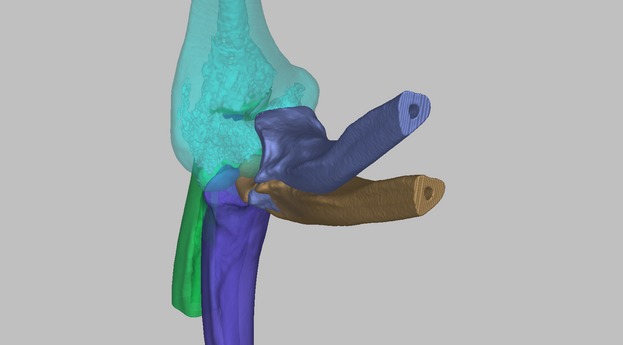
Ulna superimposition. Three-dimensional ulnohumeral joints at 45°, 90°, and 130° were superimposed onto full extension (0°) by rotating and translating every three-dimensional model along the axes.
Midpoint location
The medial aspect of the trochlea in the distal humerus was defined as the midpoint between the coronoid tip and olecranon tip in the proximal ulna (Fig. 2). The locations of the coronoid and olecranon tips were determined by assessing the cad objects from six different points of view (Fig. 3). Using medcad software and its user-defined coordinate systems, the midpoint was determined. Coordinate values were recorded to two decimal places.
Fig. 2.
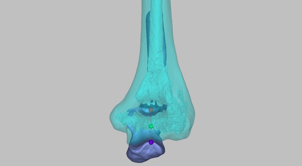
Estimation of the midpoint (green), coronoid tip (red) and olecranon tip (purple) in the proximal ulna located in the medial aspect of the trochlea of the distal humerus.
Fig. 3.
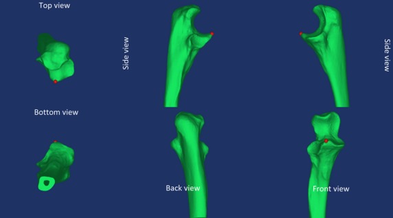
Six different points of view for assessing the tip locations.
Midpoint interpolation
Interpolation was performed to build a dynamic elbow extension–flexion model from 0° to 130°. The midpoint was interpolated by matlab software (Matlab 2012a, Mathworks, MA, USA) using the cubic spline technique (Coburn & Crisco, 2005). This software was also utilized to visualize dynamic elbow motion in a helical axis.
Basic statistical analysis
Statistical analysis was limited to the average and standard deviation due to the small number of volunteers enrolled.
Results
Two-dimensional helical axis pattern
The average midpoint pattern of joint motion from extension to flexion was elliptical-orbit-like when projected onto the sagittal plane and was continuously translated to the lateral side when assessed in the coronal and transverse planes (Fig. 4). Between full extension and 15° flexion, the average midpoint moved in the distal-posterior direction; at 15–90° flexion it moved in the distal-anterior direction; and at > 90° flexion, the average midpoint moved in the proximal-posterior direction, apparently returning to its original position.
Fig. 4.

Two-dimensional ulnohumeral helical axis pattern when projected into the (A) sagittal, (B) coronal, and (C) transverse planes.
Three-dimensional helical axis pattern
The average midpoint movement pattern of the ulnohumeral joint resembled a vortical flow along an imaginary axis. The radius had inconsistent values within the 0–130° flexion range (Fig. 5). At flexion angles of 0–15°, 15–90°, and 90–130°, the spiral pathway traveled in the distal-posterior-lateral, distal-anterior-lateral, and proximal-posterior-lateral directions, respectively. Therefore during elbow extension–flexion, the ulnohumeral joint translated as well as rotated in an irregular spiral motion, a unique pattern known as vortical flow.
Fig. 5.
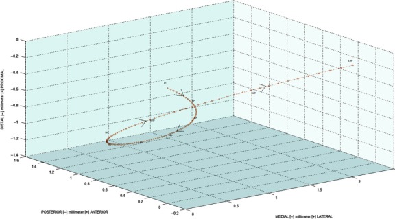
Three-dimensional vortical flow pattern of the ulnohumeral joint from full extension to 130° flexion.
Translation magnitude
The mean ± SD magnitude of ulnohumeral joint translation during elbow extension–flexion was 2.14 ± 0.34 mm (range 1.83–2.52 mm) (Table 1). Translation was linearly proportional to elbow flexion (Fig. 6). However, 105–119° flexion had the greatest translation magnitude ratio in average midpoint measurements.
Table 1.
Average magnitudes of ulnohumeral joint translation during elbow flexion and extension (mm)
| Volunteer | ||||||
|---|---|---|---|---|---|---|
| Angle (°) | 1 | 2 | 3 | 4 | Avg | SD |
| <15 | 0.42 | 0.01 | 0.04 | 0.08 | 0.14 | |
| 15–29 | 0.20 | 0.15 | 0.05 | 0.05 | 0.11 | |
| 30–44 | 0.05 | 0.26 | 0.07 | 0.05 | 0.11 | |
| 45–59 | 0.02 | 0.34 | 0.12 | 0.09 | 0.14 | |
| 60–74 | 0.02 | 0.39 | 0.18 | 0.17 | 0.19 | |
| 75–89 | 0.05 | 0.41 | 0.25 | 0.28 | 0.25 | |
| 90–104 | 0.19 | 0.40 | 0.34 | 0.43 | 0.34 | |
| 105–119 | 0.41 | 0.35 | 0.45 | 0.61 | 0.45 | |
| ≥120 | 0.47 | 0.21 | 0.39 | 0.57 | 0.41 | |
| ext-flex | 1.83 | 2.52 | 1.88 | 2.32 | 2.14 | 0.34 |
Fig. 6.
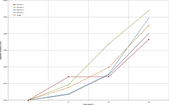
Magnitude of translation of the ulnohumeral joint during elbow extension–flexion. Translation was lowest at full extension and increased during flexion.
Discussion
The human elbow joint has been thoroughly assessed using a three-dimensional approach (Fischer, 1911; Morrey & Chao, 1976; Madey et al. 2000; Duck et al. 2003; Goto et al. 2004; Morrey & Sanchez-Sotelo, 2008; Miyake et al. 2012). Our study utilized cad software to construct three-dimensional anatomical models from CT images, to build cad objects, and to record the Cartesian coordinate system, with mathematical analysis software used to analyze and visualize dynamic elbow extension–flexion motion.
Two-dimensional analysis showed an elliptical-orbit-like pattern when projected onto the sagittal plane. This pathway resembled that of a boomerang, although it did not return to full extension (0°) but was 2.14 mm lateral to its point of origin. This translation occurred continuously and became more linear in each elbow, being most moderate at full extension and enlarging during flexion.
The helical axis of the ulnohumeral joint has been described as a roller configuration because the pathway of the screw axis of rotation exhibited a circular pattern when assessed from either the lateral or the medial side (Bottlang et al. 2000; Goto et al. 2004). In contrast, a pattern of the helical axis characterized by an intersection point within the trajectory of the locus of the instant center of rotation during elbow extension–flexion (within flexion ranges of 0–10° and 110–120° flexion) was observed when the elbow was examined from the lateral or medial side (Fischer, 1911; Morrey & Chao, 1976; Morrey & Sanchez-Sotelo, 2008). Nevertheless, the occurrence of two movements at the same time, namely, spiral motion and translation motion, resulted in no intersection and a roller configuration when the midpoint was extended into the 3D isometric projection. When occurring together, the spira and translation motions mimic a vortex-flow motion, which occurs continuously during elbow extension–flexion.
In the three-dimensional space, the midpoint between the coronoid tip and the olecranon tip in the proximal ulna, representing the axis of the ulnohumeral joint, moved uniquely during elbow extension–flexion. Its motion was much more complicated than that of a simple hinge joint. According to our average measurements, the midpoint moved in a distal-posterior-lateral direction at 0–15°, became more anterior at 15–90°, and moved in a proximal-posterior-lateral direction at 90–130°. This pattern has been called screw motion, because rotation and translation occurred continuously and simultaneously during elbow flexion-extension (Madey et al. 2000; Miyake et al. 2012). We found, however, that movement of the axis tended to simulate a vortex-flow motion pattern, also called vortical flow, because the radius of each elbow flexion arc differed. By contrast, a screw motion shows a consistent arc over its entire range of motion.
Vortical flow consists of a complex spinning motion relative to its axis. The axis of this motion is almost impossible to determine due to rapid changes in dynamic movement (Doorly et al. 2002); thus vortical flow tends to be more dynamic than screw motion. In addition to constant changes in radius during elbow extension–flexion, the magnitude of existing linear translation also changes. By contrast, screw motion is characterized by a more constant magnitude of translation during elbow flexion. Nevertheless, a larger study is needed to analyze the factors influencing this unique motion of the human elbow joint.
Elbow flexion has been regarded primarily as a spinning motion, with the elbow regarded as a simple hinge joint with an axis of rotation located at a single, definite point (Fischer, 1911; Morrey & Chao, 1976; Morrey & Sanchez-Sotelo, 2008); however, screw motion was observed in human elbow joints during elbow extension and flexion. These findings have influenced the development of medical devices to treat elbow disorders and instability (e.g. hinged external fixator and artificial elbow joint), as well as influencing surgical techniques (e.g. the medial ulnar collateral ligament reconstruction technique). Nonetheless, these medical devices and surgical techniques have been unable to restore perfectly the native flexion and extension movements in human elbow joints.
This study has several limitations, the most notable being the small number of study subjects. Use of an interpolation technique to model dynamic elbow motion may also introduce potential errors. These results, however, may prompt in vivo three-dimensional studies of elbow kinematics.
In summary, we found that the ulnohumeral joint axis rotates as well as translates during elbow extension–flexion, with a vortex-flow motion occurring during flexion. This motion can be considered when performing hinged external fixation, total elbow replacement and MCL reconstruction surgery.
Acknowledgments
This study was supported by a grant (2014-592) from the Asan Institute for Life Sciences, Asan Medical Center, Seoul, Korea.
Author contributions
A.A. contributed to study design, data analysis, and drafting the manuscript. A.L.K. contributed to study design. J.T. and H.J.L. acquired the data. M.F.D. contributed to the drafting of the manuscript. I.H.J. contributed to study design and critically revised the manuscript. All authors approved the final version of the manuscript and its submission for publication.
Conflict of interest
The authors declare that they have no conflict of interest in this study.
References
- Bottlang M, Madey SM, Steyers CM, et al. Assessment of elbow joint kinematics in passive motion by electromagnetic motion tracking. J Orthop Res. 2000;18:195–202. doi: 10.1002/jor.1100180206. [DOI] [PubMed] [Google Scholar]
- Bryce CD, Armstrong AD. Anatomy and biomechanics of the elbow. Orthop Clin North Am. 2008;39:141–154. doi: 10.1016/j.ocl.2007.12.001. v. [DOI] [PubMed] [Google Scholar]
- Byram IR, Khanna K, Gardner TR, et al. Characterizing bone tunnel placement in medial ulnar collateral ligament reconstruction using patient-specific 3-dimensional computed tomography modeling. Am J Sports Med. 2013;41:894–902. doi: 10.1177/0363546513477377. [DOI] [PubMed] [Google Scholar]
- Coburn J, Crisco JJ. Interpolating three-dimensional kinematic data using quaternion splines and hermite curves. J Biomech Eng. 2005;127:311–317. doi: 10.1115/1.1865195. [DOI] [PubMed] [Google Scholar]
- Doorly DJ, Sherwin SJ, Franke PT, et al. Vortical flow structure identification and flow transport in arteries. Comput Methods Biomech Biomed Eng. 2002;5:261–273. doi: 10.1080/10255840290010715. [DOI] [PubMed] [Google Scholar]
- Duck TR, Dunning CE, King GJ, et al. Variability and repeatability of the flexion axis at the ulnohumeral joint. J Orthop Res. 2003;21:399–404. doi: 10.1016/S0736-0266(02)00198-5. [DOI] [PubMed] [Google Scholar]
- Fischer O. Verlag Gustav Fischer. Vol. 2. Jena: 1911. Handbuch iler Anatomie und Mechanik der Gelenke, unter Berücksiclitigung der Bewegenden Muskeln; pp. 299–308. [Google Scholar]
- Goto A, Moritomo H, Murase T, et al. In vivo elbow biomechanical analysis during flexion: three-dimensional motion analysis using magnetic resonance imaging. J Shoulder Elbow Surg. 2004;13:441–447. doi: 10.1016/j.jse.2004.01.022. [DOI] [PubMed] [Google Scholar]
- Madey SM, Bottlang M, Steyers CM, et al. Hinged external fixation of the elbow: optimal axis alignment to minimize motion resistance. J Orthop Trauma. 2000;14:41–47. doi: 10.1097/00005131-200001000-00009. [DOI] [PubMed] [Google Scholar]
- Miyake J, Moritomo H, Masatomi T, et al. In vivo and 3-dimensional functional anatomy of the anterior bundle of the medial collateral ligament of the elbow. J Shoulder Elbow Surg. 2012;21:1006–1012. doi: 10.1016/j.jse.2011.07.018. [DOI] [PubMed] [Google Scholar]
- Morrey BF, Chao EY. Passive motion of the elbow joint. J Bone Joint Surg Am. 1976;58:501–508. [PubMed] [Google Scholar]
- Morrey BF, Sanchez-Sotelo J. Biomechanics of the Elbow. In: An K-N, Zobitz ME, Morrey BF, editors. The Elbow and Its Disorders. 4th edn. Philadelphia: Saunders Elsevier; 2008. pp. 39–60. [Google Scholar]


