Abstract
This paper describes an inexpensive pico-projector-based augmented reality (AR) display for a surgical microscope. The system is designed for use with Micron, an active handheld surgical tool that cancels hand tremor of surgeons to improve microsurgical accuracy. Using the AR display, virtual cues can be injected into the microscope view to track the movement of the tip of Micron, show the desired position, and indicate the position error. Cues can be used to maintain high performance by helping the surgeon to avoid drifting out of the workspace of the instrument. Also, boundary information such as the view range of the cameras that record surgical procedures can be displayed to tell surgeons the operation area. Furthermore, numerical, textual, or graphical information can be displayed, showing such things as tool tip depth in the work space and on/off status of the canceling function of Micron.
1. Introduction
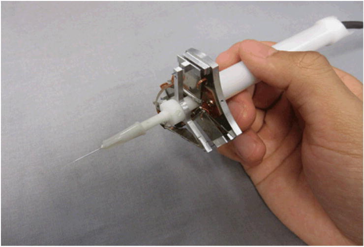
Involuntary tremor is inherent in normal human hand motion. Undesired hand motions limit accuracy in many microsurgical procedures in specialties such as ophthalmological and neurological surgery, and in fact completely prevent certain manipulations that might provide clinical benefit if they could be performed [1]. When the desired motions have the same order of magnitude as hand tremor, the signal-to-noise ratio is low, leading to poor performance or even potentially serious consequences during microsurgery. An example of a procedure that is practically infeasible today, and therefore is generally not performed, is retinal vein cannulation for injection of anticoagulants to clear vascular occlusions. Successful retinal vein cannulation generally requires accuracy at or near the level of tens of microns, which is not attainable by surgeons using passive handheld tools [1]. Several robotic microsurgical systems have been developed in response to this problem, including the “steady-hand” robotic system [2, 3] and telerobotic systems [4]. Our laboratory has followed a fully handheld approach. To cancel hand tremor for accurate medical micromanipulation, an active stabilized handheld surgical instrument, Micron, has been developed as shown in Figure 1. Micron senses its own motion, filters the motion to distinguish between desired and undesired motion, and compensates the hand tremor by actively deflecting its tip.
Figure 1.
Micron: a handheld microsurgical instrument that performs active compensation of physiological hand tremor.
To enhance the operation of Micron by surgeons, certain virtual cues and annotations can be helpful. These include, but are not limited to, the track of the movement of Micron, the indications of the current and desired locations that Micron points at and the error between the two locations, boundary information such as the view range of the cameras that take videos of the surgery procedures, and depth information about the tool tip. Conventionally, information guides and annotation to assist the use of Micron were overlaid and displayed on a 2D or 3D monitor, which could show microscopic views sensed by two cameras. However, such overlay of information had a low resolution and large latency, which limits surgeons' performance when using Micron. Also, surgeons need to look away from the microscope to watch the monitor for virtual information. A microsurgical augmented reality (AR) system that overlays biomedical imaging data within the stereo operating microscope view itself can be a valuable aid for image-guided surgery [5].
Numerous AR displays have been developed for surgical microscopes, as surveyed in [5], and clinical systems are now available, but the cost of these is high. This report presents an inexpensive monocular AR display, based on a pico-projector, which researchers can easily add to a surgical microscope. This system possesses the advantages of low cost, high stability, easy attachment as an add-on, no interruption to surgical workflow, and relatively high resolution and signal-to-noise ratio.
Various medical augmented reality technologies have been developed recently. First is optical or video see-through head-mount display (HMD) augmented reality, which enables users to observe 3D computer-generated virtual images overlaid on the real world views by wearing see-through HMDs [6]. Second is augmented optics, which augments operating microscopes and operating binoculars by adding a semi-transparent mirror to the optics. The inserted mirror reflects the virtual information to the optical pathway of the real objects [5]. Third are augmented windows, or semi-transparent mirrors put in between the real objects and users [5]. Fourth are augmented monitors that display augmented video images [5], a previous approach used in our lab as mentioned above. Fifth is direct projection onto patients [5]. Disadvantages of various systems may include high cost, limited resolution, system latency, and the wearing of cumbersome head-mounted devices.
The successful development of the AR system enables the overlay of virtual information on real objects under the microscope. Consequently, surgeons do not need to move away from the operation field and watch separate monitors. Virtual cues can be injected into the surgical microscope to track the movement of the tip of Micron, show the current position of Micron and the desired or target position, and indicate the error between the current position and desired position. In such a way, Micron can be easily operated without letting its tip drift far enough from the target to prevent active compensation from being performed. Also, boundary information such as the view range of video cameras can be displayed to tell surgeons the operation area. Furthermore, numerical, text, or graphical information such as how deep Micron is in the workspace, and whether the cancelling function of Micron is on or off, can be displayed. In addition, virtual images including reconstructed surfaces of the surgical sites and preoperative medical imaging data can be overlaid onto the surgical scene.
2. System design
The AR system consists of an optical system and a mechanical support in order to achieve the goal of injecting virtual images into the microscope. The optical system displays images clearly in the eyepieces. It is composed of a projector as the source of virtual images to be displayed, two positive lenses to focus the light, a prism to bend the optical pathway for more convenient positioning of the system, and a beam splitter that takes the projected images and reflects the light into the eyepiece of the microscope for display. The mechanical support provides a closed and rigid system for the optical components as well as a connection between the AR display system and the microscope.
2.1 Requirements
The requirements of the augmented reality system involve functionality, affordability, attachment, display model, weight, displayed image size, and resolution. The system should overlay virtual information to real objects under the microscope so that surgeons are able to observe the virtual data and real objects simultaneously in real time. In addition, the system is desired to be relatively inexpensive. It should be attached to the surgical microscope optical hardware as an add-on with a monocular display model. Also, the total weight of the system should be less than 2 kg because the maximum load allowed for the optical hardware of the microscope is 2 kg. Moreover, the size of the injected images should be no smaller than the whole eyepiece view.
2.2 Image Source
The image source of a particular medical augmented reality system is significant because it determines the image quality of the overlaid data and limits the overall performance of the system. Aschke et al. have compared three commonly-used image sources, including mini beamers, liquid crystal display panels, and micro displays [7]. They conclude with a choice of micro display. However, a micro display, although quite small and light, has the drawbacks of relatively high cost and low brightness.
A handheld pico-projector is used as the augmentation image source in our system because of its relatively low cost, low weight, high resolution, high contrast, high refresh rate, and compact form. Several factors need to be considered when choosing a pico-projector. First is the price, which ranges from about US$200 to US$400. Second is the projection technology. There are two main projection technologies: Digital Light Processing (DLP) from Texas Instruments, and Liquid Crystal on Silicon (LCoS). DLP has fewer products available and slightly lower resolution than their LCoS counterparts, but has better contrast, higher efficiency, and lower power consumption. The third factor is the light source. Most projectors use LEDs, and a few use lasers. LED projectors are cheaper and more widely used, but have the problem of focus dial. Laser projectors have the advantages of auto focus, good color gamut, and low power consumption. The focus-free operation of laser projectors allows for rapid changes in projection size, simultaneous far and near surface projection, angled projection, and projection on curved and other non-flat surfaces. However, laser projectors have poor performance in displaying text. In addition, lasers have the potential to harm the eye. The fourth factor is the output format. Most projectors have VGA and A/V outputs. Particularly, some projectors produced by Optoma have an HDMI connection that enables high resolution output. The fifth factor is brightness, which ranges from 15 lumens to 50 lumens.
Five pico-projectors were initially considered: 3M MPro 180, 3M MPro 150, AAXA L1 V2, Optoma PK301, and Optoma PK201, of which only AAXA L1 V2 is a laser projector and all the others are LED projectors. First of all, the 3M MPro 180, which is relatively expensive, was ruled out from an economic point of view because its additional functions including Wi-fi, Bluetooth, and touch screen are not needed in our specific application. Secondly, the 3M MPro 150 was ruled out because of its dependence on batteries, which make it unable to operate for an unlimited time. Thirdly, the laser projector AAXA L1 V2 was also ruled out because of the potential eye damage, although neutral density filters might prevent the possibility of such damage. In addition, the laser projector's disadvantage of not being able to focus text is problematic when text information is injected into the microscope. The Optoma PK201 and PK301 are quite similar in design, specification, and manufacturing, both being able to display when plugged in and both having a native resolution of WVGA (854 × 480) and maximum resolution of HD (1080i) through HDMI. The primary advantages of the PK301 over the PK201 are a shorter throw distance and a promised significantly brighter image with a larger and higher-quality lens. As a result, the PK301 has better definition than the PK201 for showing fine lines and details. Furthermore, the PK301 has a maximum brightness of 50 lumens when plugged in, as opposed to 20 lumens for the PK201. In addition, PK301 is better at focusing than the PK201 [8]; it was reported that the PK201 was unable to get the entire projecting surface to focus. In the end, therefore, the Optoma PK301 was the final choice for this AR system. It has a mass of 227 g, a native resolution of WVGA (854 × 480) and a maximum resolution of HD (1080i) through HDMI, a contrast ratio of 2000:1, and dimensions of 120.1 × 29.7 × 69.8 mm.
2.3 Optical System Design
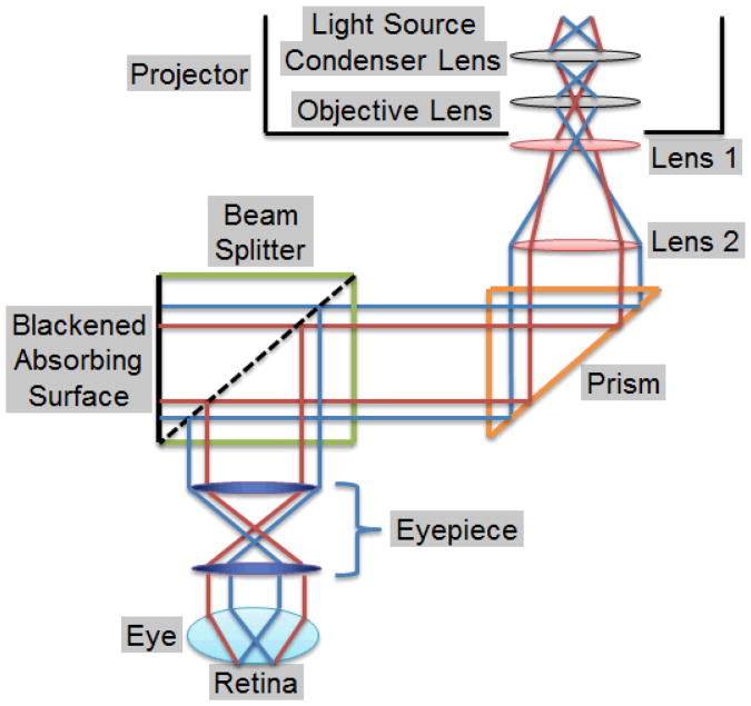
The optical system injects the virtual images from the pico-projector into the microscope eyepiece. The system is composed of two positive lenses, a prism, a Zeiss® beam splitter, and an optical filter. The two lenses first focus and then collimate the light from the pico-projector. The collimated light then goes into the beam splitter, which is modified to reflect the light to the eyepiece for overlaying of the virtual images on the microscope view. The prism bends the optical pathway by 90 degrees so that the optical system can be conveniently located along the axis of the microscope. Each component is discussed in detail below and summarized in Table 1 with its function, and the ray diagram of the optical system is shown in Figure 2.
Table1 Components of the Optical System.
| Component | Function |
|---|---|
| Lens 1 (40 mm focal length) | Focuses the light from the projector |
| Lens 2 (125 mm focal length) | Collimates the light |
| Prism | Bends the optical path for compactness |
| Beam splitter | Reflects the light into the eyepiece |
| Optical filter | Reduces the image brightness |
Figure 2.
Ray diagram of the optical system.
Two positive lenses were used to focus the projected images to human eyes. As shown in Figure 2, Lens 1 focuses the light from the projector, and Lens 2 collimates the diverged light rays before the light is injected into the microscope. The size of a projected image observed in the eyepieces is determined by the ratio of the focal length of Lens 1 to that of Lens 2 when the eyepieces and objective are fixed. The larger the ratio is, the larger the magnification is, or the less the range of the projected images observed from the eyepieces.
When choosing lenses, chromatic aberration and spherical aberration are important factors to consider. Chromatic aberration refers to the inherent color separation in glass, which can be problematic in multi-color imaging [9]. An achromatic lens is formed by cementing two optical components together, usually a positive low-index lens and a negative high-index lens [9]. It improves the performance in polychromatic imaging compared to a single lens by correcting the color separation or chromatic aberration. In addition, achromatic lenses offer smaller spot sizes and superior images without decreasing the clear aperture and enable brighter images and better energy throughput.
Spherical aberration causes the incident light rays to focus at different points and makes the image blurry [9]. An aspherized lens, whose radius of curvature varies radially from its center, creates almost no blur and therefore improves image quality by correcting for spherical aberration and making the light focus to a point. In addition, aspherized lenses make it possible to design high throughput systems with low F number and high numerical aperture while simultaneously maintain good image quality. Also, they reduce system size and overall cost of production.
To reduce both chromatic and spherical aberration, a spherical achromatic lens with a focal length of 12.5 cm, and an aspherized achromatic lens with a focal length of 4 cm, both from Edmund Optics, were chosen.
Lens 1 is placed immediately in front of the projector lens. The distance between Lens 1 and Lens 2 is approximately the focal length of Lens 2, which is 125 mm. This distance can be adjusted by a C-mount fine focus tube and a customized sliding bar, discussed in the section on mechanical support. The distance between Lens 2 and the beam splitter can be any value, because Lens 2 makes the incident light collimated before the light goes into the beam splitter.
As the total optical length of the optical system is relatively long, either a mirror or prism is needed in order to fold the optical pathway into a more compact and convenient form. Mirrors and prisms have their own advantages and disadvantages in beam steering applications. Mirrors save cost and reduce the weight of optical systems [10]. They are more favorable when used for wavelength ranges that are strongly absorbed by most types of glass, such as high-power laser application. However, mirrors may have alignment problems, and high reflectance mirrors with specific dielectric coatings are expensive. Prisms, on the other hand, have higher efficiency and less light loss than mirrors due to total internal reflection [10]. They are athermalized as a uniform piece of glass. In addition, prisms, as monolithic components, are less affected by other environmental variations than mirrors, which are individual exposed components; therefore, prisms are more durable. As a result, prisms are used more widely than mirrors. Based on the aforementioned facts, a high quality prism was chosen.
An Edmund Optics N-BK7 30-mm (length of the legs) high-tolerance right-angle prism with an aluminized hypotenuse and VIS 0° coated legs was chosen for the optical system due to its relatively high surface accuracy and surface quality and low price.
A Zeiss beam splitter, as shown on the left side of Figure 3, was used in the system to reflect the light to the eyepieces of the microscope. Beam splitters reflect 50% of the incident light and transmit the other 50%, as shown in the middle of Figure 3. Beam splitters are originally designed for splitting what surgeons see and displaying the views in computer monitors for data recording and processing. To achieve the goal of injecting images into the microscope, it was necessary to reverse that process. To accomplish this, the beam splitter was disassembled and the orientation of one of the rectangular prisms, formed by cementing two triangular prisms at their bases, was changed so that images injected into the beam splitter are reflected to the eyepieces, as shown on the right side of Figure 3.
Figure 3.

The beam splitter.
It was found that the brightness of the projected images was too high to observe comfortably with unprotected eyes. An absorptive neutral density (ND) filter with a 3.0 optical density (0.1% transmission) from Edmund Optics was used to reduce the brightness to an appropriate level. A variety of absorptive neutral density (ND) filters, which exhibit an additive relationship, is available to produce customized level of brightness.
2.4 Mechanical support
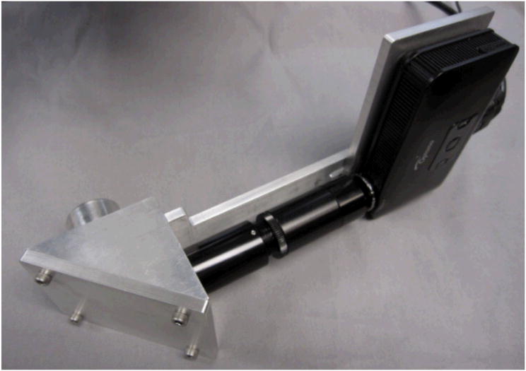
To provide a rigid and closed holder for the optical system, a mechanical support was designed using SolidWorks. The mechanical support consists of a prism holder that holds the prism, a projector holder that holds the pico-projector, a triangular part that provides an enclosed space for the prism and a holder for Lens 2 and also connects the mechanical support system to the beam splitter, and a sliding bar that connects the projector with its holder to the triangular piece and also provides fine focus adjustment for the projector. In addition, C-mount tubes, including a 4-cm extension tube, a 5-9 cm fine focus tube, and a lens mount that holds Lens 1 were used for the optical path. The assembled mechanical support has dimensions of about 300 × 150 × 100 mm.
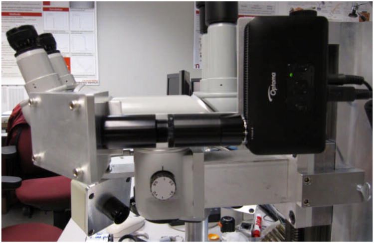
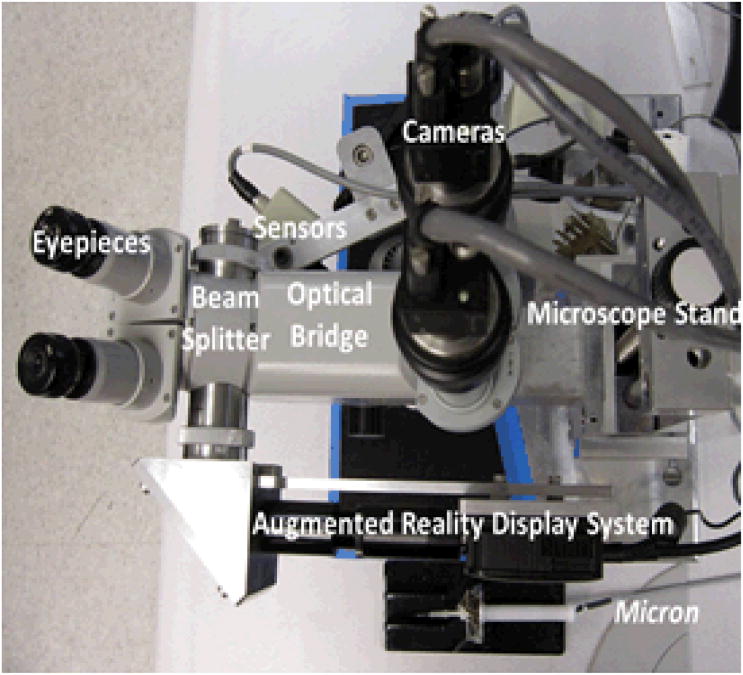
The assembled AR display system is shown in Fig. 4. The AR system attached to the stereo operating microscope is shown in Fig. 5. Figure 6 shows a bird's-eye view of the entire microsurgical system, which includes the AR display, a Zeiss OPMI 1® surgical microscope, two Flea 2® cameras (Point Grey Research, Richmond, BC, Canada) mounted to the eyepiece, and Micron.
Figure 4.
The assembled AR system.
Figure 5.
The AR system attached to the surgical microscope.
Figure 6.
View of the entire surgical system from above, showing the AR display, as well as the stereo pair of cameras and the active handheld instrument, Micron.
3. Results
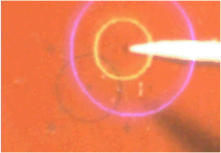
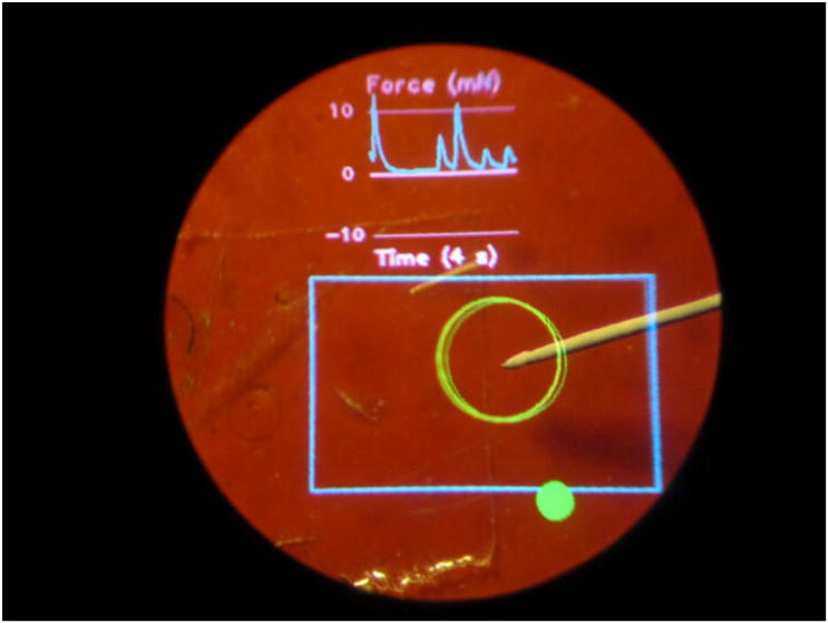
The AR display is used to present graphical cues within the microscope view for image guidance. The system is calibrated continuously using an online least squares approach [11]. The first experiment performed to test the AR system is to point at a certain point in space accurately using Micron with the help of injected virtual cues. Figure 7 shows an experimental view from one of the microscope eyepieces. The yellow circle indicates the desired position that Micron is to point at. The blue circle (which appears violet on a red background) indicates Micron's current position. The size of the blue circle provides depth information. When the tool tip is at the desired depth, the blue circle is the same size as the yellow. If the tool tip is too high, the blue circle is larger than the yellow. When the tool tip is too low, the blue circle is smaller than the yellow. Matching the two circles enables the surgeon to keep the tool centered in 3D within the workspace surrounding the target, maintaining the effectiveness of the active tremor compensation. Figure 8 shows another example, which includes both manipulation cues and a scrolling force display.
Figure 7.
Usage of AR display in the operating microscope. The yellow circle indicates the target location. The blue circle (which appears violet on the red background) indicates the current position of the tool tip; the fact that it is larger than the yellow circle indicates that the tool tip is higher than the desired elevation.
Figure 8.
Use of AR display during simulated retinal surgery. At top, a real-time graph shows force applied by the tip of Micron. The blue rectangle denotes the camera viewing area, and the large green circle shows the tracked tip location. The solid green circle at the bottom is a status indicator for Micron.
4. Discussion
The development of this AR display for the operating microscope was motivated by experimental data that indicated that for unassisted tasks (i.e., not using Micron), performance using the stereo operating microscope for visual feedback was better than when using a computer monitor for visual feedback, presumably due in part to the lower dynamic range and resolution of the cameras used for image capture when compared to the human eye [11]. When attempting to improve accuracy by the use of Micron with overlaid graphical cues, it is obviously undesirable to simultaneously degrade accuracy by using the computer monitor which has so far been used with such graphical cues. The new AR display allows these cues to be used within the operating microscope itself. More extensive testing with surgeons will indicate whether the performance difference that has been noted in preliminary unassisted testing will also be evident in assisted (tremor-compensated) tests.
Acknowledgments
Funding was provided in part by the U.S. National Institutes of Health (grant nos. R01EB000526 and R01EB007969), the National Science Foundation (Graduate Fellowship), and the ARCS Foundation.
Contributor Information
Chen Shi, Email: chenscn@u.washington.edu, Dept. of Electrical Engineering University of Washington Seattle, Washington, USA.
Brian C. Becker, Email: brianbec@ri.cmu.edu, The Robotics Institute Carnegie Mellon University Pittsburgh, Pennsylvania, USA.
Cameron N. Riviere, Email: camr@ri.cmu.edu, The Robotics Institute Carnegie Mellon University Pittsburgh, Pennsylvania, USA.
References
- 1.MacLachlan RA, Becker BC, Cuevas Tabarés J, Podnar GW, Lobes LA, Jr, Riviere CN. Micron: An actively stabilized handheld tool for microsurgery. IEEE Trans Robot. 2012;28, no. 1:195–212. doi: 10.1109/TRO.2011.2169634. [DOI] [PMC free article] [PubMed] [Google Scholar]
- 2.Taylor R, Jensen P, Whitcomb L, Barnes A, Kumar R, Stoianovici D, Gupta P, Wang Z, de Juan E, Jr, Kavoussi L. A steady-hand robotic system for microsurgical augmentation. Int J Rob Res. 1999;18:1201–1210. [Google Scholar]
- 3.Mitchell B, Koo J, Iordachita I, Kazanzides P, Kapoor A, Handa J, Hager G, Taylor R. Development and application of a new steady-hand manipulator for retinal surgery. Proc IEEE Int Conf Robot Autom. 2007:623–629. [Google Scholar]
- 4.Le Roux PD, Das H, Esquenazi S, Kelly PJ. Robot-assisted microsurgery: A feasibility study in the rat. Neurosurgery. 2001;48:584–589. doi: 10.1097/00006123-200103000-00026. [DOI] [PubMed] [Google Scholar]
- 5.Sielhorst T, Feuerstein M, Navab N. Advanced medical displays: A literature review of augmented reality. Journal of Display Technology. 2008;4:451–467. [Google Scholar]
- 6.Rolland JP, Fuchs H. Optical versus video see-through head-mounted displays in medical visualization. Presence. 2000;9:287–309. [Google Scholar]
- 7.Aschke M, Wirtz CR, Raczkowsky J, Wörn H, Kunze S. Augmented reality in operating microscopes for neurosurgical interventions. Proc 1st Int IEEE EMBS Conf Neural Eng. 2003:652–655. [Google Scholar]
- 8.Optoma Pico PK301. [Accessed August 10, 2011]; available from: http://www.optomausa.com/products/detail/pk301.
- 9.Laikin M. Lens Design. 4th. Boca Raton, Fla: CRC Press; 2007. [Google Scholar]
- 10.Yoder PR. Design and Mounting of Prisms and Small Mirrors in Optical Instruments. Bellingham, Wash: SPIE Press; 1998. [Google Scholar]
- 11.Becker BC, MacLachlan RA, Lobes LA, Jr, Riviere CN. Semiautomated intraocular laser surgery using handheld instruments. Lasers Surg Med. 2010;42:264–273. doi: 10.1002/lsm.20897. [DOI] [PMC free article] [PubMed] [Google Scholar]


