

Abstract
Non-invasive, biomedical devices have the potential to provide important, quantitative data for the assessment of skin diseases and wound healing. Traditional methods either rely on qualitative visual and tactile judgments of a professional and/or data obtained using instrumentation with forms that do not readily allow intimate integration with sensitive skin near a wound site. Here we report a skin-like electronics platform that can softly and reversibly laminate perilesionally at wounds to provide highly accurate, quantitative data of relevance to the management of surgical wound healing. Clinical studies on patients using thermal sensors and actuators in fractal layouts provide precise time-dependent mapping of temperature and thermal conductivity of the skin near the wounds. Analytical and simulation results establish the fundamentals of the sensing modalities, the mechanics of the system, and strategies for optimized design. The use of this type of ‘epidermal’ electronics system in a realistic, clinical setting with human subjects establishes a set of practical procedures in disinfection, reuse, and protocols for quantitative measurement. The results have the potential to address important unmet needs in chronic wound management.
Keywords: wound monitoring, clinical study, skin-like, multifunctional, epidermal electronics
1. Introduction
Monitoring of wound healing, a dynamic interactive biological process involving blood cells, extracellular matrix, and parenchymal cells, is of great interest in biomedical research and clinical practice. The most comprehensive means for assessment of wound healing is based on histological evaluation of tissue morphologic change,[1, 2] but this process is invasive and does not provide a means for continuous evaluation over time. Visual inspection by digital photography[1, 3, 4] overcomes these limitations, however interpretation is inherently subjective and the imaging often yields inconsistent information due to variations in lighting, focus and angle. Quantitative imaging methods via confocal laser scanning microscopy or spectroscopy can reveal microscopic level changes in the morphology of the epidermis and dermis.[4, 5] These methods, however, require patient immobilization during the testing. Also, the required sophisticated optical systems are high in cost and require trained personnel for evaluation. Recent work on simple, portable, point-of-care (POC) devices[1, 6] for optical sectioning and topical determination of wound healing phases suggest promise, although their use is ultimately limited by qualitative visual evaluation. In wound healing, calor is a primary indicator of inflammation and possible infection.[1, 7, 8] Hydration is another factor that affects wound healing.[7] Thus, monitoring of skin temperature and thermal conductivity (hydration), along with numerous other potential markers such as bacterial load, cytokine release, DNA, enzymes, hormones, pH, oxygen, and transepidermal water loss, [1] provides important clinical information.
Practical biomedical devices, capable of non-invasive, quantitative and multifunctional measurements of the healing process, are needed to complement optical and other techniques. In this communication, we introduce a skin-like electronics system capable of precise and real-time monitoring of cutaneous wound healing in a clinical setting. These devices represent a type of epidermal electronics system (EES),[8] which adopts the soft mechanical texture of the epidermis to allow conformal lamination and reversible bonding to the epidermis via van der Waals interactions alone.[9-11] The result is a natural, non-irritating and high quality interface to the skin that does not constrain natural motions or induce any discomfort.[10] EES can be designed in biocompatible, waterproof forms that are easily disinfected for clinical applications, enabling re-use. The sensors demonstrated here use microscale, metal traces in fractal layouts on soft, elastomeric membranes, capable of measurement and mapping of skin temperature with an accuracy comparable to that of a high-end infrared (IR) camera, with the additional capabilities of recording thermal conductivity and delivering precise levels of heating.
In wound healing monitoring, an EES records time-dynamic temperature and thermal conductivity of the skin tissue. Mapping of skin temperature is important because it presumably is capturing the ‘inflammation’ phase of the healing process, related to increased blood flow to the wound.[12, 13] Thermal conductivity correlates strongly to hydration state, which is another important aspect of wound care, and can serve as an early sign of the emergence of local edema.[14-16] From a practical standpoint, thermal conductivity can also serve as a sensitive indicator of quality of contact between the device and the wound, allowing the healthcare professional to assess proper mounting on the skin. Three dimensional mechanical and thermal simulations of this type of EES on human skin, through the finite element method (FEM) and the finite volume method (FVM), respectively, capture the underlying physics of this contact, as well as the mechanisms for physiological sensing mechanism. The results establish critical design criteria for clinical applications.
2. Results
2.1 Device design and mechanics modeling
Figure 1a presents a schematic view of the layouts of a multifunctional EES of the type used in the studies reported here. The device uses a multilayer construct that consists of metal traces with fractal geometries (Peano curve motif) in an interconnected collection of ultrathin filamentary serpentine (FS) interconnects and an open mesh configuration. Contact pads provide connection points to external data acquisition hardware. The fractal configuration offers superior elastic stretchability compared to conventional meandering structures[17] and, in the context reported here, enables precise thermal measurements in ways that are largely unaffected by mechanical strains associated with mounting onto the complex cutaneous wound shapes on the skin. Finite element modeling (FEM) analysis (Supplementary Note 1 and Figure S1) illustrates quantitatively the elastic properties of the fractal geometry chosen for present purposes, with a comparison to other fractal options, as well as conventional designs such as regular curves and serpentines. The sensors are integrated onto thin silicone membranes (dyed black to facilitate control measurements of temperature with an IR camera) by the techniques of transfer printing, and subsequently coated with an encapsulating layer of silicone. [18]The resulting EES offers effective elastic moduli (22.1 kPa, measured by DMA Q800, TA instruments, USA) significantly lower than the epidermis (100-150 kPa). Figure 1b – 1e shows the response upon 30 % uniaxial stretching (Figure 1b), multimodal folding (Figure 1c), biaxial stretching and twisting (Figure 1d), and 720° twisting (Figure 1e). The device fabrication follows procedures described briefly in the Methods section, with details in Supplementary Note 2 and Figure S2 and S3. The process exploits conventional microfabrication techniques to form electronic structures on a silicon wafer coated with a sacrificial polymer, as a temporary carrier substrate. The conducting elements use 3 μm-thick copper (Cu) traces deposited by electron-beam evaporation. Layers of polyimide (PI; 1.2 μm in thickness, Sigma-Aldrich, USA) above and below place the Cu fractal (width: 35 μm) and FS traces (width: 50 μm) at the neutral mechanical plane (NMP) to minimize the bending strains. Water soluble tapes pick up the electronic patterns from the carrying wafer and transfers to a silicone membrane (500 μm in thickness, ~20 kPa in modulus; Ecoflex, Smooth-On, USA; Figure 1a). [10] A 5 μm thick layer of silicone spin cast on top of the device encapsulates the EES to provide a water-proof surface capable of sterilization for use in clinical studies with human patients. [18]
Figure 1.

Device design and mechanics modeling. (a) Schematic illustration of an EES. (b) Image of an device under uniaxial stretching , multimodal folding (c) and biaxial stretching and twisting (d) and 720° twisting (e). (f) Top view and tilted view (g) microXCT images of the device in (d). (h) FEM analysis and experimental study of a fractal construct under uniaxial stretching; FEM (top) and experiment (bottom). The inset in the middle illustrates the neutral mechanical plane (NMP) of the metal with polyimide (PI) encapsulation.
Figure 1f (top view) and 1g (tilted view) show microscale X-ray coherent tomography images (microXCT, Xradia, USA) of such a device. [19] The fractal construct accommodates levels of mechanical strain upon biaxial, radial stretching that exceed maximum values (~30 %) typically experienced in the skin. [8] Details of the microXCT imaging process appear in the Supplementary Note 3. FEM analysis (details in Supplementary Figure S4) and experimental studies with microXCT (Figure 1h) reveal that the fractal systems can be stretched elastically, with reversible mechanics, by ~15 % and ~30% with only 0.25 % and 0.85 % maximum principal strain in the Cu (elastic strain of Cu: 0.3 %; fracture strain of Cu: 5%),[20-22] respectively. The results (Figure 1h) suggest ability to ensure consistent, reproducible device function and operation at and beyond levels of deformation that can be tolerated by the skin (10 – 20 %).[9, 18]
2.2 Multifunctional characteristics
Figure 2 summarizes the hardware and capabilities of an integrated collection of components, consisting of data acquisition systems and an EES with an array of sensors and actuators, configured for multipoint mapping of temperature and thermal conductivity. The devices include an EES (wound compatible device), a current source (6221, Keithley Instruments, USA), a lock-in amplifier (SR830, Stanford Research Systems, USA), a multiplexer (FixYourBoard.com, U802, USA), and a laptop (Figure 2a). A thin, flexible ribbon cable (HST-9805-210, Elform, USA) connects the array of six sensors/actuators in the EES to a multiplexer that enables sequential operation for spatial recording of temperature and thermal conductivity. The measurement uses a four point-probe technique for determining voltage drop in the sensors[17] upon changes in temperature or mechanical strain (Supplementary FigureS5). Figure 2b lists representative operating parameters for the lock-in amplifier in thermal conductivity and temperature measurements. Custom software presents a user-friendly interface that automatically calculates relevant parameters from voltages recorded through a GPIB cable interface (NI GPIB-USB-HS, National Instruments Corp., USA) to the computer. Changes in electrical resistance of the fractal constructs allow determination of changes in temperature, through a calibration curve (Figure 2c) established using data from an IR camera (precision <50 mK, A655SC, FLIR, USA) and a precisely controlled hot plate (details in Supplementary Note 4). The resistance is calculated by measured voltage drop in the sensors. The measured precision of an EES is ~50 mK, determined by limitations in the analogue-to-digital converter. Absolute accuracy in clinical testing is ~200 mK, determined by the use of the constant current source.
Figure 2.

Multifunctional characteristics. (a) Data acquisition system. (b) Parameters of the lock-in amplifier for measurement of temperature and thermal conductivity. (c) Electrical resistance of six sensors in an EES, as a function of surface temperature. (d) Measurement of thermal conductivity by an EES. (e) Simulation of the oscillating temperature distribution induced in the skin by the EES. (f) IR thermography during Joule heating (35 mA) using one of the sensors in the EES as a micro-heater. (g) Simulation of the rise in temperature on the surface of the device upon Joule heating (35 mA). (h) Simulation of the rise in temperature on the skin tissue on the device surface upon Joule heating.
Evaluation of thermal conductivity uses an alternating current (AC) method adapted from techniques previously used in other contexts, known as the 3 omega (3ω) method. [23] Here, an AC current applied to the fractal structures induces both heating and changes in resistance that, in turn, influence the heating levels. This nonlinear coupling leads to a voltage output at the third harmonic of the AC drive. The magnitude of this signal is influenced by the thermal conductivity of the contacting material, i.e. the human skin. Details of the measurement schemes and calibration procedures in this case appear in Supplementary Note 5. The frequency dependence of the 3ω voltage signals for operation in air and the associated amplitude of the temperature oscillations appear in Supplementary Figure S7 and S8, respectively. 3ω voltages measured at two different AC frequencies can be used with a simple analytical expression to determine the thermal conductivity: [23]
| (1) |
where R0 is the nominal resistance of the sensor, Irms is the applied root-mean-square (RMS) current at 1ω, fH is a selected higher frequency, fL is a lower frequency, l is the length of the sensor, and V3ω is the measured RMS voltage at 3ω (L and H denote lower and higher, respectively), and dR/dT is resistance change as a function of temperature. Calibration with known values of thermal conductivity is required to account for various aspects of the device structure and non-linearity in the response. Chosen two frequencies in the measurement offer the best compromise of skin characterization and reduced time for clinical measurement on patients.
Figure 2d presents the calibrated relationship between the thermal conductivity measured using an EES for six examples where the conductivity is known (air, concentrations of 0, 25, 50, 75, and 100 % ethanol in water). [24] The measurements involve probing to effective depths that depend on various details, including the frequency, as illustrated in results of Figure 2e obtained by numerical analysis for the case of a simplified model of human skin. Here, a quasi-steady-state form of the heat conduction equation can be solved at the operating frequency by the finite volume method (FVM) with the 2D approximations[25] (details in Supplementary Note 6 and Table S1). The amplitude of oscillation temperature on the fractal sensor (Figure 2e) decreases sharply from the EES and skin contact, and later converges in the dermis layer. The characteristic distribution of these curves follows expected patterns as reported earlier. [26] For frequencies used in our clinical studies (i.e. V3ωL = 1 Hz and V3ωH = 3 Hz), the measured thermal conductivity is influenced by properties of both the epidermis and dermis.
We note that the heating functionality needed for assessment of thermal conductivity might be advantageous separately in a therapeutic mode. The steady-state temperature distribution associated with Joule heating is important in this context. Modeling of the well-known Pennes bioheat transfer equation, with FVM and 2D approximations (Supplementary Note 7), yields results shown in Figure 2g. Figure 2h presents calculated temperature distributions for various input currents, where increased temperature can be observed down to the dermis layer. Applied currents (35, 50, and 65 mA) yield peak temperatures of 38, 42, and 46 °C, respectively. These temperatures can be measured and controlled accurately by using the heaters simultaneously as temperature sensors. This study indicates, therefore, some potential of an EES for therapeutic use since local heating is known to promote healing of chronic wounds[27, 28] and has been used in hyperthermia treatment of some skin cancers.[27, 29-31]
2.3 Device characterization
The mechanical, thermal and measurement properties are critical to the operation of these types of devices. For example, mechanical deformations can induce strains in the sensors, with the potential to change their resistances in ways that might confound temperature and thermal conductivity measurements. This effect can have practical importance, simply because uniaxial stretching and multimodal bending can occur in the process of applying and removing the device from skin. These mechanical deformations may also cause slight, permanent changes in the resistance of the sensors by plastic deformation. Fractal choices in layout, guided by FEM analysis of the mechanics, can minimize such effects. [17] Figure 3a shows the contribution of cyclic uniaxial loading to a maximum elongation of 15 %. The device is first stretched to 15 % and then released back to 0 % (details in Supplementary Note 8). The measurements reveal elastic elongation and release response without hysteresis in the stress-strain curve (Figure 3a). The resistance change of 0.025 % at 15 % elongation changes the apparent temperature reading by only 0.05 °C. Figure 3b shows that temperature changes due to bending are negligible (temperature shift: < 0.01 °C) in the bending radius between 15 and 45 mm. Results indicated relatively small effects of deformation on thermal measurement; further reductions are possible with refined device designs.
Figure 3.

Device characterization. (a) Effect of mechanical stretching on the measured temperature. (b) Effect of bending on the measured temperature. (c) IR thermogram of the forearm with an EES mounted. (d) Temperature distribution on the skin measured by the IR camera and the EES along blue dotted line shown in (c). The horizontal axis shows the distance from the top of the heater. (e) EES mounted on the forearm with a wet paper towel that covers sensor #3. (f) Distribution of measured thermal conductivity of the skin. The value from sensor #3 shows a clear, expected difference from the other sensors. (g) Thermal conductivity of air, 50% ethanol and acrylic sheet measured after multiple cycles of cleaning. The straight lines in the graph show the actual values. (h) Thermal conductivity measured on the forearm with 20 measurements in one individual.
Direct and simultaneous comparison of temperature recordings using an EES and IR camera supports the accuracy and reproducibility of measurements of temperature, as outlined in Supplementary Note 9. Figure 3c presents an IR thermogram of a forearm with an EES laminated on the skin, revealing increased temperature in locations of arteries. Figure 3d compares temperature distributions on the skin measured from using the EES with that from an IR camera. Due to thermal convection on the air-exposed surface of the device, the skin temperature from an EES is slightly higher than (0.6±0.4 °C) that from the IR thermogram. The shifted IR thermogram temperature matches well with EES data. The thermal conductivity must be assessed independently, as this quantity cannot be determined with the IR camera. Figure 3e presents a measurement on the forearm with a wet piece of paper under sensor #3. The locally increased thermal conductivity results in an expected increased thermal conductivity reading from this sensor. Other sensors yield values that are typical epidermis thermal conductivity values (0.1 - 0.3 W/mK) (Figure 3f).
For practical application in the clinic, these measurement capabilities must not be altered by standard procedures for disinfection of devices that are placed on the skin, such as rubbing the application area with isopropyl alcohol antiseptic. [32-34] Per protocol, each EES was prepared immediately prior to use (details in Supplementary Note 10 and Figure S19). Device functions were verified with multiple cleaning steps for repetitive use demonstration, by recording thermal conductivity values at three different conditions. The graph in Figure 3g presents measurement results after cleaning procedures with air exposure, 50 % ethanol/water mixture, and acrylic board (OPTIX, Plaskolite, USA) over multiple cycles of cleaning. Values in all cases are consistent with the known thermal conductivity values, indicated by the straight lines. Related evaluations on the skin can be accomplished by examining repeatability in measurements performed at a single anatomic site. Figure3h shows thermal conductivity values from 20 measurements. Results show good consistency, with a precision of ~4 %. This result is important because it suggests that the soft construction of the EES allows conformal contact with the surface of the skin, consistent with previous observations in other contexts. [16] The interfacial contact adhesion between the EES and the skin was measured as ~0.5 N/m from the mechanical peel tests using a force gauge (Mark-10, USA).[10]
2.4 Use of EES on human subjects in a clinical setting
Adhesion and skin irritation of the EES vs. conventional medical skin tape (3M, USA; major ingredient, acrylate polymer)[10] was determined after mounting on the forearm (Figure 4a – 4g). Observation of the skin by a digital contact microscope (AM7013MT Dino-Lite, AnMo Electronics, USA) after mounting was used to assess skin irritation (erythema and scaling ) qualitatively. Despite more than 30 episodes of mounting and removal on the same anatomic skin site, EES did not cause any clinical evidence of irritation (Figure 4a and 4b). In contrast, acrylate-based medical tape caused slight erythema upon removal from the skin (Figure 4c-1), likely due to partial exfoliation of stratum corneum by the adhesive (Figure 4c-2). The silicone surface of the EES has hydrophobic methyl groups, unlike the hydrophilic surface of the acrylate tape, which presents hydroxyl groups (Figure 4d and 4e). The general, non-covalent interfaces of the EES offer sufficient adhesion for conformal contact (Figure 3h), similar to the adhesion of dry skin adhesives.[35-38] To further assess the potential impact of EES on keratinocyte (skin cell) viability, normal human keratinocytes were seeded onto the EES and viability was tested with a live/dead staining assay kit. Fluorescence microscopic images show that most cells cultured on the EES remain viable (stained as ‘red’)[39-41] (Figure 4f).
Figure 4.

Use of an EES on human subjects in a clinical setting. (a) EES laminated on the skin (forearm) after sterilization. (b) Microscope images of the skin with thirty attempts of mounting and removal of an EES. (c) Microscope image of the skin after the medical tape removal (1) and image of the tape surface (2). (d) Illustration of the materials interface between the EES and skin (e) Illustration between the medical tape and skin. (f) Fluorescence images of viability of skin cells grown on an EES (left) and the control on the regular cell culture materials (right). Most of cells on the EES remain viable (‘red’ cells). (g) Clinical setting for wound monitoring in a typical exam room. (h) EES laminated on wound and contralateral (control) sites. (i) Assessment sequence and estimated time.
Three subjects undergoing incisional cutaneous wounding for skin lesions were enrolled (Figure 4g and 4h). Two devices were used: one in proximity to the surgical wound site and the other at the comparable area on the contralateral side as a control for evaluating time dynamic natural variations in body temperature. Optimization of the system construction and recording parameters enabled rapid, multi-point evaluation of temperature and thermal conductivity, as well as comparison of the former results simultaneously obtained with an IR camera, everything within only 10 minutes (Figure 4i). Figure 5a presents images at day 1, 3, 15, and 30 with the EES in intimate contact perilesionally to the cutaneous wound and can be compared with IR thermography at a single time point for comparison (Figure 5b). Measurements from the contralateral site are in Supplementary Figure S20. The EES for temperature and thermal conductivity recording uses six sensing components with 45 mm long spatial coverage. Figure 5c presents variations in temperature recorded by the six sensors, as shown by arrows (inset) from day 1 to day 30. The normalized data (Figure 5c, right) demonstrates relative temperature difference adjacent to the wound site compared with normal skin. The sudden temperature rise on day 3, as indicated in the graph, captures the inflammation phase, which is thought to be due to increased blood flow and enzymatic reactions. [1, 12, 13, 42] The control experiment (Figure 5d) on the contralateral site measures the baseline temperature without wounding. The measurement of localized, tissue thermal conductivity with the same device enables the assessment of conformal contact and skin hydration (Figure 5e). [16] On day 3 when the wound is considered to be in the inflammation phase, the corresponding thermal conductivity is slightly lower than at other time frames. To our knowledge, no previous studies have reported such subtle hydration variation, especially on hypersensitive wound tissue, during the wound healing process. Other works regarding hydration monitoring have typically focused only on the effect of balancing the hydration level in wound healing, [1] dressing materials, [43] or as in vitro only testing with a simulated wound bed. [7]
Figure 5.

Quantitative monitoring of a granulating wound with an EES. (a) Representative photos of the wound with an EES from day 1 to day 30. (b) Corresponding IR images of the temperature distribution associated with (a). (c) Temperature distribution recorded with an EES (inset) from wound skin to normal skin during one month. The six sensors span a distance of 45 mm in lateral direction. (d) Temperature distribution on a contralateral side. (e) Thermal conductivity (T.C.) distribution recorded with three sensors in an EES (inset). (f) Thermal conductivity (T.C.) on a contralateral side as a control.
One subject (Subject 3) had a long surgical incision with suturing (Figure 6), protected by a dressing for the first two post-surgical weeks (Figure 6a). IR thermography captured temperature change for comparison with data obtained with the EES (Figure 6b). Another subject (Subject 1) had a granulating wound which showed elevated calor on day 3, but also temperature elevation on day 15 (Figure 6c), perhaps reflecting prolonged, more intense inflammation. [1, 12, 44] Temperature variation near the wound site was clearly and reproducibly distinguishable from the minimal variance of the contralateral, control body temperature (Figure 6d). In the sutured wound, the extended inflammation phase demonstrated stable thermal conductivity during a prolonged period and differed from the temperature pattern of the granulating wound (Figure 6e). Temperature and thermal conductivity change on the contralateral site are shown in Supplementary Figure S21. Subject 2, also with a granulating wound, showed a similar trend in measurements to Subject 1 (Table 1 and Supplementary Figure S22).
Figure 6.
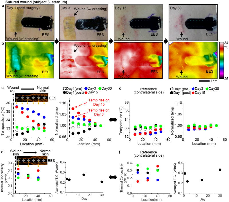
Quantitative management of sutured wound with an EES. (a) Representative photos of the wound with an EES from day 1 to day 30. (b) Corresponding IR images of the temperature distribution associated with (a). (c) Temperature distribution recorded with an EES (inset) from wound skin to normal skin during one month. The six sensors span a distance of 45 mm in lateral direction. (d) Temperature distribution on a contralateral side. (e) Thermal conductivity (T.C.) distribution recorded with three sensors in an EES (inset). (f) Thermal conductivity (T.C.) on a contralateral side as a control.
Table 1.
Summary of clinical study with 3 subjects.
| Subject 1 | Subject 2 | Subject 3 | |
|---|---|---|---|
| Wound type | Granulated | Granulated | Sutured |
| Age | 62 | 79 | 54 |
| Sex | Male | Female | Male |
| Race | White, Caucasian | White, Caucasian | White, Caucasian |
| Site of lesion | Left medial inner ankle | Right shin | Sternum |
| Device contact* | Conformal | Conformal | Conformal |
| Temperature rise | On day 3 | On day 15 | On day 3 and 15 |
Assessment by thermal conductivity measurement
3. Discussion
Stretchable, conformal, multifunctional system design and layouts, in unusual forms, enable quantitative physiological measurements in patients, an innovation in cutaneous wound management. The stretchable electronic device offers material and mechanical properties that are well-matched to human skin, allowing new levels of integration of biotic and abiotic systems that was previously precluded by hard, flat or merely flexible devices. Biocompatible, ultra-soft silicone completely encloses the electronics system (effective moduli: ~22 kPa, thickness: ~500 μm) to provide enhanced gentle wearability on hypersensitive wound tissue, simple disinfection, and re-use capabilities that are favorably required in the clinical setting. Multimodal functions, design criteria, and spatial mapping of physiological assessment on the skin by an EES, well-understood and supported by three dimensional FEM and FVM analysis in mechanics and thermodynamics, opens a new route for continuous, quantitative, long-term monitoring in clinical wound management.
Possible improvement includes a new device configuration in an ultra-thin, more compliant but robust set that can be directly laminated over a wound tissue for wound management without interference of natural skin interface. More functions to monitor electromyogram, pH level, mechanical strain change, and transepidermal water loss can be added into the multifunctional electronics. Another set of devices with purely based on thermochromic polymers without electric circuits, along with a simple digital imaging, would enable a cheap, portable, but quantitative monitoring of skin temperature without the use of sophisticated electronic devices and signal filtering/processing. Furthermore, incorporation with a wireless powering and transmission system that has integrated circuits in stretchable forms would deliver the ultimate concept of home-setting assessment of wound management, as in a smart healthcare system.
4. Conclusion
In conclusion, this communication has introduced the use of a multifunctional, conformal EES in cutaneous wound management for patient applicability. Sets of micro-metal resistors demonstrated the multimodal measurement of high precision skin temperature, thermal conductivity in disinfected, re-use configuration and also showed the actuation function as micro-heaters. This class of technology is expanded further, with the support of three dimensional finite element methods, to address unresolvable needs that include biocompatible, noninvasive, continuous monitoring of skin physiology in chronic wound management.
5. Experimental Section
Fabrication of an EES
The device processing used conventional microfabrication techniques (details in Supplementary Note 2 and Figure S2 and S3). A carrier substrate was prepared by spin coating thin layers of polydimethylsiloxane (PDMS; 10 μm in thickness, Dow Corning, USA) and polyimide (PI; 1.2 μm in thickness, Sigma-Aldrich, USA) on a 3 inch silicon wafer. Electron beam evaporation formed 3 μm-thick layers of Cu on the substrate. Photolithography and etching defined the fractal and FS traces. A water soluble tape (3M, USA) retrieved the completed patterns from the carrier wafer, for subsequent transfer and covalent bonding onto a black silicone membrane (Ecoflex, Smooth-On, USA). To provide electrical isolation for clinical use, a 5 μm-thick layer of silicone was coated on top of patterns. For data acquisition, a flexible, anisotropic ribbon cable made electrical contact to the connection pads.
Biaxial stretching and imaging
Biaxial mechanical stretching of a fractal sensing component of an EES involved mounting onto a home-made plate with circular opening above an air chamber. Connecting the chamber to an external pump allowed controlled adjustment of biaxial strain induced by inflation. Three dimensional, micro X-ray tomography (Xradia, USA) was used to image microscale behaviors of the fractal traces (details in Supplementary Note 3).
Clinical study on patients
All experiments on patients were conducted under a protocol (number: STU69718) approved by the Institutional Review Board, Northwestern University, Chicago, IL, USA. Prior to study entry, subjects signed written informed consents per adherence to Helsinki Guidelines. Research was carried out in a clinical exam room at the central Northwestern Medical Group Dermatology Clinic (676 North St. Clair Street, Suite 1600, Northwestern University, Feinberg School of Medicine, Chicago, IL, USA).
Supplementary Material
Acknowledgments
W.-H. Y. thanks Jongwoo Lee, Dong Sup Lee, and Ohjin Kwon for help with the schematic illustration, material preparation and data analysis. This study was supported by the National Science Foundation under Grant DMI-0328162 and the US Department of Energy, Division of Materials Sciences under Award No. DE-FG02-07ER46471 through the Materials Research Laboratory and Center for Microanalysis of Materials (DE-FG02-07ER46453) at the University of Illinois at Urbana-Champaign. This research utilized Core resources provided by the NIH-funded Northwestern University Skin Disease Research Center (NIAMS, P30AR057216). H.C. is a Howard Hughes Medical Institute International Student Research fellow. W.-H.Y. acknowledges the support of startup fund from the Virginia Commonwealth University. J.A.R. acknowledges a National Security Science and Engineering Faculty Fellowship.
Footnotes
Supporting Information
Supporting Information is available from the Wiley Online Library or from the author.
Contributor Information
Dr. Yoshiaki Hattori, Department of Materials Science and Engineering and Frederick Seitz Materials Research Laboratory, University of Illinois at Urbana-Champaign, Urbana, IL 61801, USA
Leo Falgout, Department of Materials Science and Engineering and Frederick Seitz Materials Research Laboratory, University of Illinois at Urbana-Champaign, Urbana, IL 61801, USA.
Woosik Lee, Department of Electrical Engineering, University of Illinois at Urbana-Champaign, Urbana, IL 61801, USA.
Sung-Young Jung, Department of Mechanical Engineering, Pohang University of Science and Technology, Pohang, 790-784, Republic of Korea.
Dr. Emily Poon, Department of Dermatology, Feinberg School of Medicine, Northwestern University, Chicago, IL 60611, USA
Dr. Jung Woo Lee, Department of Materials Science and Engineering and Frederick Seitz Materials Research Laboratory, University of Illinois at Urbana-Champaign, Urbana, IL 61801, USA
Ilyoun Na, Department of Chemical Engineering, Pohang University of Science and Technology, Pohang, 790-784, Republic of Korea.
Amelia Geisler, Department of Dermatology, Feinberg School of Medicine, Northwestern University, Chicago, IL 60611, USA.
Divya Sadhwani, Department of Dermatology, Feinberg School of Medicine, Northwestern University, Chicago, IL 60611, USA.
Dr. Yihui Zhang, Department of Civil and Environmental Engineering, Department of Mechanical Engineering, Center for Engineering and Health and Skin Disease Research Center, Northwestern University, Evanston, IL 60208, USA Department of Engineering Mechanics, Tsinghua University, Beijing, 100084, China.
Dr. Yewang Su, Department of Civil and Environmental Engineering, Department of Mechanical Engineering, Center for Engineering and Health and Skin Disease Research Center, Northwestern University, Evanston, IL 60208, USA Department of Engineering Mechanics, Tsinghua University, Beijing, 100084, China.
Dr. Xiaoqi Wang, Department of Dermatology, Feinberg School of Medicine, Northwestern University, Chicago, IL 60611, USA
Prof. Zhuangjian Liu, Institute of High Performance Computing, A*star, 1 Fusionopolis Way, #16-16, Connexis 138632, Singapore
Jing Xia, Department of Civil and Environmental Engineering, Department of Mechanical Engineering, Center for Engineering and Health and Skin Disease Research Center, Northwestern University, Evanston, IL 60208, USA; Department of Engineering Mechanics, Tsinghua University, Beijing, 100084, China.
Huanyu Cheng, Department of Civil and Environmental Engineering, Department of Mechanical Engineering, Center for Engineering and Health and Skin Disease Research Center, Northwestern University, Evanston, IL 60208, USA.
R. Chad Webb, Department of Materials Science and Engineering and Frederick Seitz Materials Research Laboratory, University of Illinois at Urbana-Champaign, Urbana, IL 61801, USA.
Dr. Andrew P. Bonifas, Department of Materials Science and Engineering and Frederick Seitz Materials Research Laboratory, University of Illinois at Urbana-Champaign, Urbana, IL 61801, USA
Philip Won, Department of Materials Science and Engineering and Frederick Seitz Materials Research Laboratory, University of Illinois at Urbana-Champaign, Urbana, IL 61801, USA.
Dr. Jae-Woong Jeong, Department of Materials Science and Engineering and Frederick Seitz Materials Research Laboratory, University of Illinois at Urbana-Champaign, Urbana, IL 61801, USA
Dr. Kyung-In Jang, Department of Materials Science and Engineering and Frederick Seitz Materials Research Laboratory, University of Illinois at Urbana-Champaign, Urbana, IL 61801, USA
Prof. Young Min Song, Department of Electronic Engineering, Pusan National University, Busan, 609-735, Republic of Korea
Dr. Beatrice Nardone, Department of Dermatology, Feinberg School of Medicine, Northwestern University, Chicago, IL 60611, USA
Michael Nodzenski, Department of Dermatology, Feinberg School of Medicine, Northwestern University, Chicago, IL 60611, USA.
Dr. Jonathan A. Fan, Department of Materials Science and Engineering and Frederick Seitz Materials Research Laboratory, University of Illinois at Urbana-Champaign, Urbana, IL 61801, USA
Prof. Yonggang Huang, Department of Civil and Environmental Engineering, Department of Mechanical Engineering, Center for Engineering and Health and Skin Disease Research Center, Northwestern University, Evanston, IL 60208, USA
Dr. Dennis P. West, Department of Dermatology, Feinberg School of Medicine, Northwestern University, Chicago, IL 60611, USA
Dr. Amy S. Paller, Department of Dermatology, Feinberg School of Medicine, Northwestern University, Chicago, IL 60611, USA
Dr. Murad Alam, Department of Dermatology, Feinberg School of Medicine, Northwestern University, Chicago, IL 60611, USA
Prof. Woon-Hong Yeo, Email: whyeo@vcu.edu, Department of Mechanical and Nuclear Engineering and Institute for Engineering and Medicine, Virginia Commonwealth University, Richmond, VA 23284, USA.
Prof. John A. Rogers, Email: jrogers@illinois.edu, Department of Materials Science and Engineering, Beckman Institute for Advanced Science and Technology, and Frederick Seitz Materials Research Laboratory, University of Illinois at Urbana-Champaign, Urbana, IL 61801, USA.
References
- 1.Dargaville TR, Farrugia BL, Broadbent JA, Pace S, Upton Z, Voelcker NH. Biosens Bioelectron. 2013;41:30. doi: 10.1016/j.bios.2012.09.029. [DOI] [PubMed] [Google Scholar]
- 2.Panuncialman J, Hammerman S, Carson P, Falanga V. J Invest Dermatol. 2009;129:S47. [Google Scholar]
- 3.Hess CT, Kirsner RS. Advan Skin Wound Care. 2003;16:246. doi: 10.1097/00129334-200309000-00015. [DOI] [PubMed] [Google Scholar]
- 4.Lange-Asschenfeldt S, Bob A, Terhorst D, Ulrich M, Fluhr J, Mendez G, Roewert-Huber HJ, Stockfleth E, Lange-Asschenfeldt B. J Biomed Opt. 2012;17:076016. doi: 10.1117/1.JBO.17.7.076016. [DOI] [PubMed] [Google Scholar]
- 5.Crane NJ, Elster EA. J Biomed Opt. 2012;17:010902. doi: 10.1117/1.JBO.17.1.010902. [DOI] [PubMed] [Google Scholar]
- 6.Serena T. Protease Activity Levels Associated with Healing Status of Chronic Wounds. 2011 http://www.systagenix.com/cms/uploads/NG42-11_Serena_et_al_Protease_Activity_Levels_Associated_with_Healing_Status_of_Chronic_Wounds_Wounds_UK_2011_004.pdf.
- 7.Guo S, DiPietro LA. J Dent Res. 2010;89:219. doi: 10.1177/0022034509359125. [DOI] [PMC free article] [PubMed] [Google Scholar]
- 8.Matzeu G, Losacco M, Parducci E, Pucci A, Dini V, Romanelli M, Di Francesco F. Ieee Ind Elec (IECOn 2011) 2011:3533. [Google Scholar]
- 9.McColl D, Cartlidge B, Connolly P. Int J Surg. 2007;5:316. doi: 10.1016/j.ijsu.2007.02.008. [DOI] [PubMed] [Google Scholar]
- 10.Kim DH, Lu NS, Ma R, Kim YS, Kim RH, Wang SD, Wu J, Won SM, Tao H, Islam A, Yu KJ, Kim TI, Chowdhury R, Ying M, Xu LZ, Li M, Chung HJ, Keum H, McCormick M, Liu P, Zhang YW, Omenetto FG, Huang YG, Coleman T, Rogers JA. Science. 2011;333:838. doi: 10.1126/science.1206157. [DOI] [PubMed] [Google Scholar]
- 11.Jeong JW, Yeo WH, Akhtar A, Norton JJS, Kwack YJ, Li S, Jung SY, Su YW, Lee W, Xia J, Cheng HY, Huang YG, Choi WS, Bretl T, Rogers JA. Adv Mater. 2013;25:6839. doi: 10.1002/adma.201301921. [DOI] [PubMed] [Google Scholar]
- 12.Yeo WH, Kim YS, Lee J, Ameen A, Shi LK, Li M, Wang SD, Ma R, Jin SH, Kang Z, Huang YG, Rogers JA. Adv Mater. 2013;25:2773. doi: 10.1002/adma.201204426. [DOI] [PubMed] [Google Scholar]
- 13.Yeo WH, Webb RC, Lee W, Jung S, Rogers JA. Proc Spie. 2013:8725. [Google Scholar]
- 14.Helfman T, Ovington L, Falanga V. Clin Dermatol. 1994;12:121. doi: 10.1016/0738-081x(94)90262-3. [DOI] [PubMed] [Google Scholar]
- 15.Singer AJ, Clark RAF. New Engl J Med. 1999;341:738. doi: 10.1056/NEJM199909023411006. [DOI] [PubMed] [Google Scholar]
- 16.Huang X, Cheng HY, Chen KL, Zhang YL, Zhang YH, Liu YH, Zhu CQ, Ouyang SC, Kong GW, Yu CJ, Huang YG, Rogers JA. Ieee T Bio-Med Eng. 2013;60:2848. doi: 10.1109/TBME.2013.2264879. [DOI] [PubMed] [Google Scholar]
- 17.Huang X, Yeo WH, Liu YH, Rogers JA. Biointerphases. 2012;7:52. doi: 10.1007/s13758-012-0052-8. [DOI] [PubMed] [Google Scholar]
- 18.Webb RC, Bonifas AP, Behnaz A, Zhang YH, Yu KJ, Cheng HY, Shi MX, Bian ZG, Liu ZJ, Kim YS, Yeo WH, Park JS, Song JZ, Li YH, Huang YG, Gorbach AM, Rogers JA. Nat Mater. 2013;12:1078. doi: 10.1038/nmat3755. [DOI] [PMC free article] [PubMed] [Google Scholar]
- 19.Fan JA, Yeo W-H, Su Y, Hattori Y, Lee W, Jung S, Zhang Y, Liu Z, Cheng H, Falgout L, Bajema M, Coleman T, Gregoire D, Larson R, Huang Y, Rogers JA. Fractal Design Concepts for Stretchable Electronics. Nat Commun. 2013;5:3266. doi: 10.1038/ncomms4266. [DOI] [PubMed] [Google Scholar]
- 20.Jeong JW, Kim MK, Cheng H, Yeo WH, Huang X, Liu Y, Zhang Y, Huang Y, Rogers JA. Adv Healthc Mater. 2013 doi: 10.1002/adhm.201300334. [DOI] [PubMed] [Google Scholar]
- 21.Song YM, Xie YZ, Malyarchuk V, Xiao JL, Jung I, Choi KJ, Liu ZJ, Park H, Lu CF, Kim RH, Li R, Crozier KB, Huang YG, Rogers JA. Nature. 2013;497:95. doi: 10.1038/nature12083. [DOI] [PubMed] [Google Scholar]
- 22.Davis JR. Asm Specialty Handbook: Copper and Copper Alloys. ASM International; 2001. [Google Scholar]
- 23.Riley WF, Sturges LD, Morris DH. Mechanics of Materials. John Wiley & Sons; New York: 1999. [Google Scholar]
- 24.Zhang YH, Xu S, Fu HR, Lee J, Su J, Hwang KC, Rogers JA, Huang YG. Soft Matter. 2013;9:8062. doi: 10.1039/C3SM51360B. [DOI] [PMC free article] [PubMed] [Google Scholar]
- 25.Cahill DG. Rev Sci Instrum. 1990;61:802. [Google Scholar]
- 26.Assael MJ, Charitidou E, Wakeham WA. Int J Thermophys. 1989;10:793. [Google Scholar]
- 27.Choi SR, Kim D. Rev Sci Instrum. 2008;79:064901. doi: 10.1063/1.2937180. [DOI] [PubMed] [Google Scholar]
- 28.Gram RQ, She A, Craxton RS, Harding DR. J Appl Phys. 2012;112:033504. [Google Scholar]
- 29.Haemmerich D, Laeseke PF. Int J Hyperthermia. 2005;21:755. doi: 10.1080/02656730500226423. [DOI] [PubMed] [Google Scholar]
- 30.Kim DH, Wang SD, Keum H, Ghaffari R, Kim YS, Tao H, Panilaitis B, Li M, Kang Z, Omenetto F, Huang YG, Rogers JA. Small. 2012;8:3263. doi: 10.1002/smll.201200933. [DOI] [PubMed] [Google Scholar]
- 31.Gannon CJ, Cherukuri P, Yakobson BI, Cognet L, Kanzius JS, Kittrell C, Weisman RB, Pasquali M, Schmidt HK, Smalley RE, Curley SA. Cancer-Am Cancer Soc. 2007;110:2654. doi: 10.1002/cncr.23155. [DOI] [PubMed] [Google Scholar]
- 32.Juang T, Neuman D, Schlorff J, Stauffer PR. ieee, in Proceedings of the 26th Annual International Conference of the Ieee Engineering in Medicine and Biology Society, Vols 1-7; Ieee, New York. 2004. p. 3467. [DOI] [PubMed] [Google Scholar]
- 33.Koo YS, Fathy AE, Kazemi R, Phillips J. Ieee, in 2012 Ieee Antennas and Propagation Society International Symposium; Ieee, New York. 2012. [Google Scholar]
- 34.Infection Control Manual. 2010 https://practicegreenhealth.org/pubs/sharing/SHC_InfectionControlPolicy_7%2010CleaningofEquipment.pdf (Stanford Hospital and Clinics)
- 35.McDonnell G, Russell AD. Clin Microbiol Rev. 1999;12:147. doi: 10.1128/cmr.12.1.147. [DOI] [PMC free article] [PubMed] [Google Scholar]
- 36.Rutala WA, Weber DJ. Centers for Disease Control and Prevention. 2008 [Google Scholar]
- 37.Karp JM, Langer R. Nature. 2011;477:42. doi: 10.1038/477042a. [DOI] [PMC free article] [PubMed] [Google Scholar]
- 38.Kwak MK, Jeong HE, Suh KY. Adv Mater. 2011;23:3949. doi: 10.1002/adma.201101694. [DOI] [PubMed] [Google Scholar]
- 39.Kwak MK, Pang C, Jeong HE, Kim HN, Yoon H, Jung HS, Suh KY. Adv Funct Mater. 2011;21:3606. [Google Scholar]
- 40.Laulicht B, Langer R, Karp JM. P Natl Acad Sci USA. 2012;109:18803. doi: 10.1073/pnas.1216071109. [DOI] [PMC free article] [PubMed] [Google Scholar]
- 41.Choi YJ, Chae S, Kim JH, Barald KF, Park JY, Lee SH. Sci. Rep. 2013;3:1921. doi: 10.1038/srep01921. [DOI] [PMC free article] [PubMed] [Google Scholar]
- 42.Jung HC, Moon JH, Baek DH, Lee JH, Choi YY, Hong JS, Lee SH. Ieee T Bio-Med Eng. 2012;59:1472. doi: 10.1109/TBME.2012.2190288. [DOI] [PubMed] [Google Scholar]
- 43.Lee SM, Kim JH, Byeon HJ, Choi YY, Park KS, Lee SH. J Neural Eng. 2013;10:036006. doi: 10.1088/1741-2560/10/3/036006. [DOI] [PubMed] [Google Scholar]
- 44.Pan CP, Shi YH, Amin K, Greenberg CS, Haroon Z, Faris GW. Biomed Opt Express. 2010;1:285. doi: 10.1364/boe.1.000285. [DOI] [PMC free article] [PubMed] [Google Scholar]
- 45.Queen D, Orsted H, Sanada H, Sussman G. Int Wound J. 2004;1:59. doi: 10.1111/j.1742-4801.2004.0009.x. [DOI] [PMC free article] [PubMed] [Google Scholar]
Associated Data
This section collects any data citations, data availability statements, or supplementary materials included in this article.