Abstract
Purpose
To characterize modified triaxial microwave antennas configured to produce short ablation zones.
Materials and Methods
50 single- and 27 paired-antenna hepatic ablations were performed in domestic swine (n=11) with 17-gauge, gas-cooled modified triaxial antennas powered at 65W from a 2.45 GHz generator. Single-antenna ablations were performed at 2 (n=16), 5 (n=21), and 10 (n=13) minutes. Paired-antenna ablations were performed at 1-cm and 2-cm spacing for 5 (n=7, n=8) and 10 minutes (n=7, n=5). Mean transverse width, length and aspect ratio of sectioned ablation zones were measured and compared.
Results
For single antennas, mean ablation zone length was 2.9±0.45, 3.5±0.55 and 4.2±0.40 cm at 2, 5, and 10 minutes respectively. Mean width was 1.8±0.3, 2.0±0.32, 2.5±0.25 cm at 2, 5, and 10 minutes. For paired antennas, mean length at 5 min 1 and 2 cm and 10 min 1 and 2 cm spacing was 4.2±0.9, 4.4±0.9, 4.8±0.5 and 4.3±0.9 cm respectively. Mean width was 3.1±1.0, 4.0±0.8 and 3.8±0.4, 4.2±0.6 cm respectively. Paired-antenna ablations were more spherical (aspect ratios 0.72-0.79 for 5-10 min) than single-antenna ablations (0.57-0.59). For paired-antenna ablations, 1 cm spacing appeared optimal, with improved circularity and decreased clefting compared to 2 cm spacing (circ 1 cm 0.85, 2 cm 0.78).
Conclusion
Modified triaxial antennas can generate relatively short, spherical ablation zones. Paired-antenna ablations were rounder and larger in transverse dimension compared to single antenna ablations, with 1 cm spacing optimal for confluence of the ablation zone.
Introduction
Although radiofrequency ablation has been the most commonly used and researched heat based modality to date, microwave ablation is gaining increased adoption due to a variety of advantages. These include more rapid generation of hotter temperatures, larger ablation zones when using high power, decreased susceptibility to heat sinks, and improved energy penetration in lung, bone and charred/dessicated tissue (1-6). Despite these advantages, a substantial limitation to using microwaves is the length of the ablation zone, which is often substantially greater than the transverse dimension and can be upwards of 6-8 cm when using a single antenna (7-10). These larger, longer, hotter ablations could have increased potential to cause damage to adjacent vulnerable structures or burns to the body wall if not carefully monitored. Further, many tumors are somewhat spherical and longer ablation zones may lead to increased treatment of normal background organs proximal and distal to the mass. To date, in vivo reports of microwave ablation have focused on increasing the transverse diameter of the ablation zone, often at the cost of increased length (7-10).
Ablation zone length is impacted by many factors, including antenna design and radiating segment, frequency/wavelength, ablation time, and applied power(11-14). A dual slot antenna design has shown promise in producing a shorter, more spherical ablation zone, but is not yet commercially available (15, 16). Several vendors may be working on an antenna to generate shorter ablation zones. A gas-cooled modified triaxial antenna has recently become commercially available which has been designed to produce shorter, tip-weighted ablation zones. The purpose of this study was to test and characterize both single and paired modified triaxial antennas in an in vivo swine model.
Materials and Methods
Animals, Anesthesia and Overview of Procedures
Approval for this study was obtained from the institutional research animal care and use committee, and all husbandry and experimental studies were compliant with the National Research Council (see http://www.nap.edu/catalog/php?record_id=12910). Eleven female domestic swine (Arlington Farms, Arlington, Wis) were used for this study. Preanesthetic sedation was achieved with ketamine. Sedated animals were intubated, and anesthesia was maintained with inhaled isoflurane (Halocarbon Laboratories, River Edge, NJ). The liver was surgically exposed at laparotomy with a bilateral subcostal incision to enable applicator placement and to verify proper positioning. Microwave ablation was then performed in each of four distinct liver lobes, and different ablation times were distributed among the animals to reduce sampling bias. Following the ablation procedures (which took approximately 2-3 hours), animals were euthanized with an overdose of pentobarbital sodium and phenytoin sodium (Beuthanasia-D; Schering-Plough, Kenilworth, NJ). Zones of ablation were immediately excised and sectioned as described below.
Microwave Ablations
All microwave ablations were performed from an open approach using 17-gauge gas-cooled modified triaxial antennas with a 15 mm radiating segment (Precision, PR 15, NeuWave Medical, Madison WI). Microwave power was applied continuously at 65 W from the 2.45-GHz solid state generator. A total of 50 single-antenna ablations were performed for 2 (n=16), 5 (n=21), and 10 minutes (n=13). These time periods were selected based on prior in vivo work and clinical experience with a conventional triaxial antenna (10). At least one ablation was performed in each lobe of each porcine liver. A total of 27 paired-antenna ablations were also performed in a similar fashion, with the antennas spaced 1 or 2 cm apart and both powered at 65 W for 5 (n=7, n=8) and 10 minutes (n=7, n=5) respectively. These times and spacings were also based on prior in vivo/ex vivo work and clinical experience (17-19).
Measurements of Ablation Zone Size and Shape
Ablation zones were excised en bloc and were sectioned parallel to the ablation applicator to optimize length measurements (coronal to the applicators for the paired antennas). Samples were optically scanned (Perfection 2450 Photograph, model G860A; Epson, Long Beach, Calif) and saved as electronic images. Standard ablation zone metrics including length, transverse dimension, area, and aspect ratio (width:length) were analyzed using free software (ImageJ; 1.45s, National Institutes of Health, Bethesda, MD)(20). Circularity was measured for the paired-antenna ablations.
Statistical Analysis
Descriptive statistics of each metric (mean length, transverse dimension, area, aspect ratio) were calculated at each time point for both single and paired MW ablations, and are reported as mean ± 1 SD (standard deviation). Volumes were also calculated using the formula for the volume of an ellipsoid (4/3∏abc). The single antenna modified triaxial data was compared across time points using a Wilcoxon rank sum test. The paired antenna data was compared by time within spacing and then by spacing within time using a Wilcoxon rank sum test. Length and area of paired antenna ablation zones were also compared to single antenna ablations performed at the same time and power using Kruskal-Wallis tests with Wilcoxon rank sum test used for the two comparisons of each of the two-antenna ablations against the single antenna. The analysis did not account for clustering of lobes within animals because lobes were considered as independent. Exploratory and diagnostic plots were obtained to assess the validity of statistical test assumptions. A P-value less than 0.05 was considered to indicate a significant difference. There was no adjustment of p-values for multiplicity. Statistical analyses were performed in R2.15.2 (R Development Core Team 2012)(21).
Results
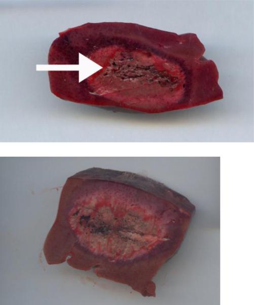
The mean ablation zone lengths for single-antenna ablations at 2 min, 5 min and 10 min (65 W) were 2.9±0.45, 3.5±0.55 and 4.2±0.4 cm respectively (figure 1). These ablation zones had corresponding transverse dimensions of 1.8±0.27, 2.0±0.32, and 2.5±0.25 cm, respectively. Aspect ratios for all single antenna ablations were approximately 0.6 (table 1, figure 1). There was significant growth in both length and area between 2 and 5 minutes (p=0.001, p=0.01) with continued significant growth from 5 to 10 minutes (p=0.0009, p<0.0001).
Figure 1.
Examples of scanned sectioned ablation zones performed with single microwave antennas at 2 min (a) and 5 min (b). These were sectioned parallel to the probe (see probe tract, arrow a) to optimize length measurements. Note the somewhat spherical ablation zones, particularly at 5 min (b).
Table 1.
Single modified triaxial antenna microwave ablation dimensions
| Time (min) | Length (cm) | Transverse dimension (cm) | Area (cm2) | Volume (cm3) | Aspect ratio (Trv:length) |
|---|---|---|---|---|---|
| 2 (n=16) | 2.9±0.45 | 1.8±0.27 | 3.9±1.0 | 4.9±1.9 | 0.61±0.09 |
| 5 (n=21) | 3.5±0.55 | 2.0±0.32 | 5.3±1.4 | 7.4±2.9 | 0.57±0.13 |
| 10 (n=13) | 4.2±0.4 | 2.5±0.25 | 8.1±1.5 | 14.2±3.3 | 0.59±0.07 |
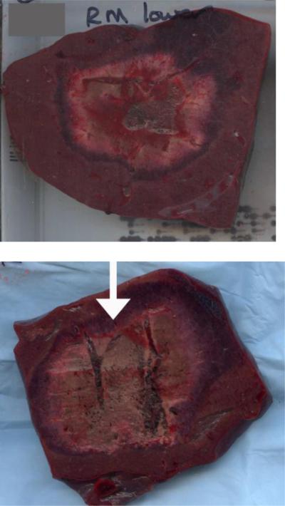
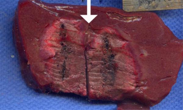
The paired antenna ablations showed lengths of 4.2±0.9 and 4.9±1.0 cm for 5 minute ablations (65W each antenna) at 1 cm and 2 cm spacing, respectively. Lengths of 4.8±0.5 and 4.8±1.3 cm were seen at 10 minutes, 1 and 2 cm spacing. Transverse dimensions were 3.1±1.0 and 4.4±0.7 at 5 minutes, 1 and 2 cm spacing respectively. Transverse dimensions were 3.8 ±0.4 and 4.5±0.7 cm at 10 minutes, 1 and 2 cm spacing respectively. Paired-antenna ablations were more spherical than single-antenna ablations, with aspect ratios greater than 0.7 (figure 2, table 2). There was a prominent trend toward significant growth in the transverse dimension and area between 5 and 10 minutes at 1 cm spacing (p=0.07, p=0.053). There was a statistically significant increase in length between 5 and 10 minutes at 1 cm spacing (p=0.05). There was no significant difference in length, transverse diameter or area between 5 and 10 minutes at 2 cm spacing. At an ablation time of 5 minutes, there was no significant difference in length between 1 and 2 cm spacing (p=0.2), but there was a significant difference in transverse dimension (p=0.02) and in area (p=0.04). At an ablation time of 10 minutes, there was no statistically significant difference in length, transverse dimension or area at a spacing of 1 vs 2 cm. There was a trend toward significance in transverse diameter at 2 cm spacing (p=0.1). However, qualitatively, ablation zones performed at the 2 cm spacing would often develop a bilobed appearance (figure 3). In addition, overall, ablations performed at 1 cm spacing showed slightly improved circularity (0.85) compared to ablations performed at 2 cm spacing (0.78). Calculated volumes showed similar trends.
Figure 2.
Examples of scanned section paired antenna ablations, performed for 5 minutes at 1 cm (a) and 2 cm (b) spacing. The 2 cm spacing showed slightly larger ablation zones, but with occasional slight clefting (arrow, b) that was more prominent at 10 minutes.
Table 2.
Paired modified triaxial antenna microwave ablation dimensions
| Time (min) | Spacing (cm) | Length (cm) | Transverse dimension (cm) | Area (cm2) | Volume (cm3) | Aspect ratio (Trv:length) |
|---|---|---|---|---|---|---|
| 5 | 1 | 4.2±0.9 | 3.1±1.0 | 11.2±6.4 | 25.2±25 | 0.72±0.18 |
| 5 | 2 | 4.9±1.0 | 4.4±0.6 | 16.3±4.1 | 50.5±16 | 0.9±0.21 |
| 10 | 1 | 4.8±0.5 | 3.8±0.4 | 14.3±3.3 | 36.7±9.1 | 0.79±0.11 |
| 10 | 2 | 4.8±1.0 | 4.5±0.7 | 15.6±6.2 | 50.8±24 | 1.0±0.322 |
Figure 3.
Two antenna ablation performed for 10 minutes at 2 cm spacing. Note the slightly bilobed appearance or clefting at the top of the ablation zone (arrow). This was qualitatively noted on multiple ablation zones, suggesting that 1 cm spacing may be optimal.
When comparing single to paired antenna ablations, there was a significant increase in transverse dimension and area at the 5 minute time point for the both the 1 and 2 cm spacings. Although there was a significant increase in length at the 2 cm spacing (p=0.002), this did not meet statistical significance for the 1 cm spacing (p=0.06). There was a significant increase in area and transverse dimension when comparing single to paired antenna at the 10 minute time point for both spacings, but no significant increase in length at the 2 cm spacing (table 3).
Table 3.
Single vs Paired antenna microwave ablation dimensions
| Number of antenna | Time (min) | Spacing (cm) | Length (cm) | Transverse dimension (cm) | Area (cm2) | Volume (cm3) | P-value (single vs paired) |
|---|---|---|---|---|---|---|---|
| Single | 5 | n/a | 3.5±0.55 | 2.0±0.3 | 5.3±1.4 | 7.4±2.9 | |
| Paired | 5 | 1 | 4.2±0.9 | 3.1±1.0 | 11.2±6.4 | 25.2±25 | Length 0.06, trv dim 0.005, area <0.001 |
| Paired | 5 | 2 | 4.9±1.0 | 4.4±0.7 | 16.3±4.1 | 50.5±16 | Length 0.002, trv dim <0.001, area <0.001 |
| Single | 10 | n/a | 4.2±0.4 | 2.5±0.3 | 8.1±1.5 | 14.2±3.3 | |
| Paired | 10 | 1 | 4.8±0.5 | 3.8±0.4 | 14.3±3.3 | 36.7±9.1 | Length 0.02, area <0.001, trv dim <0.001 |
| Paired | 10 | 2 | 4.8±1.3 | 4.5±0.7 | 15.6±6.2 | 50.8±24 | Length 0.6, area 0.002, 0.001 |
Discussion
Microwaves have many theoretical advantages as a heat based ablation modality, but one of the limitations has been the length of the ablation zone generated. In this study, we began to characterize a modified triaxial antenna created to generate short ablations zones in an in vivo porcine model. Although single antennas create relatively elliptical ablations, the length was around 4 cm, despite continued growth of the transverse dimension over time. Paired antennas created more spherical ablations, with increased transverse dimension compared to single antenna ablations, but with slightly less prominent increases in length. One-cm spacing appeared optimal due to increased clefting and decreased circularity seen at 2-cm spacing (figures 2, 3).
Multiple series have reported microwave ablation zone lengths greater than 5 cm (table 4) or qualitatively described elongated, somewhat cylindrical, rather than round ablation zones (7-10). To date, there has been limited commercial availability of a microwave antenna capable of generating short ablation zones similar to those seen with radiofrequency ablation but still capturing the other potential advantages of microwave ablation. The results of this study show that a modified triaxial antenna is able to generate shorter ablation zones than those described in the literature using other antenna designs.
Table 4.
Selected In vivo Microwave Ablation zone dimensions
| Study | System | Antenna Gauge | Diameter (cm) | Length (cm) |
|---|---|---|---|---|
| Wright et al, 2005(7) | 915 MHz, 40W, 10 min, H2O cooling | 13 g |
Short axis 1.7±0.4, max diam 2.4±0.4 |
6.8±1.0 |
| Brace et al, 2007(21) | 2.45GHz, 68 W, H2O cooling | 14.5 g |
2 min: 2.3 6 min: 2.6 12 min: 2.9 |
Not reported |
| Awad et al, 2007(8) | 2.45 GHz, 100W, 2-8 min | >6 g |
Mean short axis 2 min: 3.7±0.6 4 min: 3.8±0.5 8 min: 5.3±0.6 |
Mean long axis 2 min: 4.5±0.9 4 min: 4.9±0.5 8 min: 6.4±1.1 |
| Hines-Peralta et al, 2006(9) | 2.45 GHZ, 150W, 8 min | >6 g |
In vivo short axis 5.7 ±0.2 |
6.5±1.7 |
| Ianitti et al, 2007(28) | 915 MHz, 45 W, 10 min | 14 g | 1.59±3.5 | Not reported |
When compared to data acquired in a similar in vivo model using a single conventional triaxial antenna, the single modified triaxial antenna showed shorter ablation zone lengths (3.5-4.2 cm for the modified triaxial and 5.3-5.8 cm for the conventional triaxial antenna at 5-10 min). It is important to keep in mind that the conventional triaxial antenna was powered in vivo at 140 W compared to 65 W on the modified triaxial antenna, which could also impact the length.
However, long ablation zones can be seen even at lower powers (Table 4), suggesting that this effect is not due to differences in power alone. In fact, single-antenna microwave ablations performed with a modified triaxial antenna were comparable in length to, but more spherical than, RF ablation zones generated under similar conditions (10). Similarly, Mulier et al performed a large literature search evaluating the reported size and geometry of hepatic radiofrequency lesions. There was a relative paucity of length data, but in in vivo porcine models, lengths ranging from 2-4.4 cm were reported with a variety of devices including straight water cooled needles and umbrella or deployable devices (22). In HCC and metastatic lesions, very little length data is reported but one study treating metastatic lesions reports lengths of 3.4 cm±0.3 using a 3 cm active zone water cooled straight needle (23). The lengths seen with this modified triaxial antenna are similar.
The single-antenna ablations showed significant growth from 2 to 5 minutes, and from 5 to 10 minutes, unlike RF ablations performed under similar conditions, which showed little growth between 5 and 10 minutes (10). This is most likely due to differences in mechanism of heating (volume heating with dielectric hysteresis vs conduction of current through increasingly charred, dessicated tissue).
Not surprisingly, paired modified triaxial antennas generated larger ablation zones than a single antenna. Notably, this growth is seen more in the transverse dimension with less prominent increases in length, so that paired-antenna ablation zones remained round. There was also growth in size of the ablation zone between 5 and 10 minutes, with increases seen in transverse dimension, area, volume and length. One would expect larger ablation zones with longer time periods, but this may be complicated by the possibility of increased tissue contraction for longer ablation times, which may decrease the final ablation zone size (24).
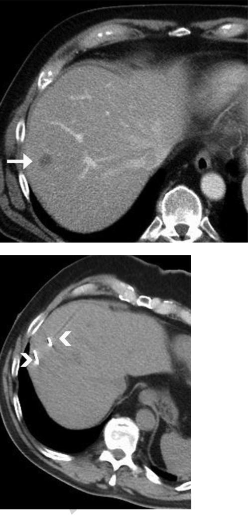
Although larger ablation zones, particularly in transverse dimension and area, were seen at 2 cm spacing compared to 1 cm, the differences seemed largely due to the additional separation and were not statistically significant at the 10 minute time point. In fact, since the difference in the mean transverse dimension of the ablation zone was 7 mm at 10 min, less than the additional 10 mm separation between antennas, it seems possible that the added separation actually decreased the thermal synergy between the antennas. Indeed, many of the ablations created with a 2 cm separation were qualitatively more clefted or bilobed in appearance and were less circular, which has also been seen with the clinical application of this antenna (figure 4). This data would suggest that 1 cm spacing is preferred.
Figure 4.
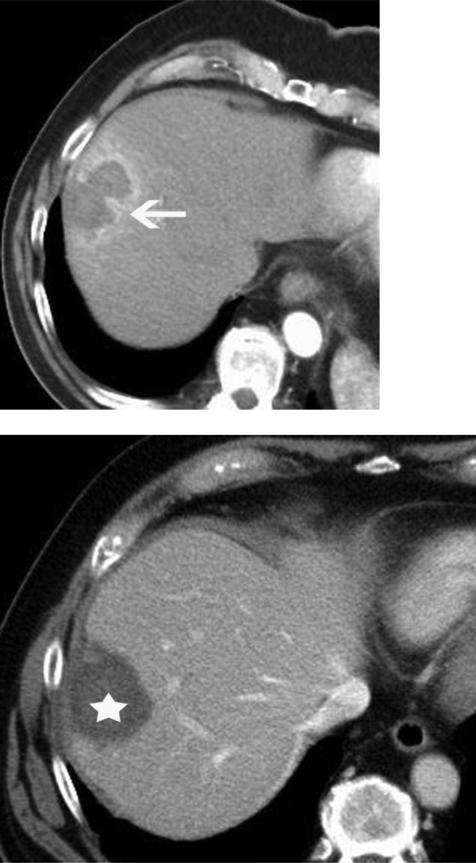
Microwave ablation of a colorectal metastatic lesion. Preablation contrast enhanced CT image (a) demonstrates a small low attenuation lesion (arrow), representing metastatic colorectal cancer. Intraprocedural non contrast CT image (b) demonstrates two antennas spaced 2 cm apart (arrowheads). These were run for 7 minutes at 65 W and created the bilobed ablation seen on the post contrast post ablation CT image (arrow, c). The probes were repositioned approximately 1 cm apart and additional treatment was performed with production of a more rounded ablation zone (*, d).
This antenna has been very promising in early clinical use, generating round, tip-weighted ablation zones as described in the in vivo model (figure 5). This shorter, tip-weighted ablation zone creates additional flexibility in the application of microwave technology and may expand microwave applications. For large tumors or metastatic disease, where a large ablation zone is needed, a more conventional antenna design can be utilized. However, for small tumors adjacent to vulnerable structures, a modified antenna design such as a modified triaxial antenna could be used where in the past, a user might consider switching to a radiofrequency applicator. A small, short tip-weighted, round ablation zone could be used more readily in the retroperitoneum to treat renal tumors, to treat small osseous lesions such as osteoid osteomas or may be more practical for use in nerve ablation for chronic pain.
Figure 5.
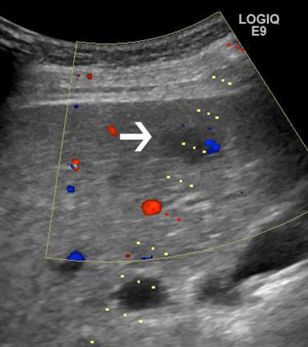
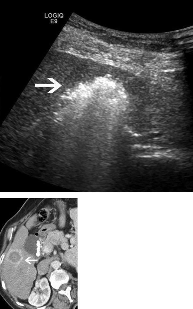
Microwave ablation performed in a cirrhotic patient with an 18 x 15mm HCC. The preablation MRI demonstrates arterial enhancement (a) and washout (b) within the tumor (arrows), consistent with HCC. Intraprocedural US (c) redemonstrates the hypoechoic lesion (arrow), with the steam cloud encompassing the lesion in (d). A single antenna was run for 5 minutes at 65W, creating a spherical ablation zone measuring 2.8 × 2.8 cm, shown on axial post procedure contrast enhanced CT (arrow, e,).
This study was limited by the exclusive use of normal porcine liver rather than a tumor model or cirrhotic liver. Recent data using a water-cooled 2.45 GHz system at 100 W (Amica, HS Medical, Boca Raton, FL) suggest that the expected performance in human tumors can be expected to lie somewhere between the performance seen in ex vivo and in vivo normal porcine livers (meeting abstract/unpublished data, Goldberg SN, Meloni F, Tosoratti N, Nissenbaum I, Appelbaum L, Solbiati L. World Conference on Interventional Oncology, 2011). Sectioning of the ablation zones directly parallel and coronal to the applicator can be challenging and may introduce some variability of measurements. The antennas were tested in single tissue type (liver), therefore translation into other tissues may require some additional study. All ablations were performed with a single microwave system and frequency.
This study has shown that short, tip-weighted ablation zones can be generated with single and paired modified triaxial microwave antennas. This has the potential to be an important tool in the ablation armamentarium, capturing the advantages of microwave without the length seen generated by many available systems. Continued exploration of other antenna designs may be helpful, to continue to optimize the shorter microwave ablation zone.
Acknowledgments
Work was funded in part by: NIH R01CA142737, R01CA149379
Footnotes
Publisher's Disclaimer: This is a PDF file of an unedited manuscript that has been accepted for publication. As a service to our customers we are providing this early version of the manuscript. The manuscript will undergo copyediting, typesetting, and review of the resulting proof before it is published in its final citable form. Please note that during the production process errors may be discovered which could affect the content, and all legal disclaimers that apply to the journal pertain.
Disclosures: T. Ziemlewicz, M. Lubner: None
J. Louis Hinshaw: Shareholder, Medical board member, Neuwave Medical Inc, Madison WI
Lisa Sampson: Research consultant, Neuwave Medical Inc, Madison WI
Chris Brace: Shareholder, Research consultant, Neuwave Medical Inc, Madison WI
Fred T. Lee Jr: Shareholder, patent holder and board of directors, Neuwave Medical Inc, Madison WI; Patent holder, inventor, royalties Covidien AG.
References
- 1.Bhardwaj N, Dormer J, Ahmad F, et al. Microwave ablation of the liver: a description of lesion evolution over time and an investigation of the heat sink effect. Pathology (Phila) 2011;43(7):725–31. doi: 10.1097/PAT.0b013e32834c356c. [DOI] [PubMed] [Google Scholar]
- 2.Bhardwaj N, Strickland AD, Ahmad F, Atanesyan L, West K, Lloyd DM. A comparative histological evaluation of the ablations produced by microwave, cryotherapy and radiofrequency in the liver. Pathology (Phila) 2009;41(2):168–72. doi: 10.1080/00313020802579292. [DOI] [PubMed] [Google Scholar]
- 3.Brace CL. Radiofrequency and microwave ablation of the liver, lung, kidney, and bone: what are the differences? Curr Probl Diagn Radiol. 2009;38(3):135–43. doi: 10.1067/j.cpradiol.2007.10.001. [DOI] [PMC free article] [PubMed] [Google Scholar]
- 4.Brace CL, Hinshaw JL, Laeseke PF, Sampson LA, Lee FT., Jr Pulmonary thermal ablation: comparison of radiofrequency and microwave devices by using gross pathologic and CT findings in a swine model. Radiology. 2009;251(3):705–11. doi: 10.1148/radiol.2513081564. [DOI] [PMC free article] [PubMed] [Google Scholar]
- 5.Dodd GD, 3rd, Dodd NA, Lanctot AC, Glueck DA. Effect of variation of portal venous blood flow on radiofrequency and microwave ablations in a blood-perfused bovine liver model. Radiology. 2013;267(1):129–36. doi: 10.1148/radiol.12120486. [DOI] [PubMed] [Google Scholar]
- 6.Wright AS, Lee FT, Jr., Mahvi DM. Hepatic microwave ablation with multiple antennae results in synergistically larger zones of coagulation necrosis. Ann Surg Oncol. 2003;10(3):275–83. doi: 10.1245/aso.2003.03.045. [DOI] [PubMed] [Google Scholar]
- 7.Wright AS, Sampson LA, Warner TF, Mahvi DM, Lee FT., Jr Radiofrequency versus microwave ablation in a hepatic porcine model. Radiology. 2005;236(1):132–9. doi: 10.1148/radiol.2361031249. [DOI] [PubMed] [Google Scholar]
- 8.Awad MM, Devgan L, Kamel IR, Torbensen M, Choti MA. Microwave ablation in a hepatic porcine model: correlation of CT and histopathologic findings. HPB : the official journal of the International Hepato Pancreato Biliary Association. 2007;9(5):357–62. doi: 10.1080/13651820701646222. [DOI] [PMC free article] [PubMed] [Google Scholar]
- 9.Hines-Peralta AU, Pirani N, Clegg P, et al. Microwave ablation: results with a 2.45-GHz applicator in ex vivo bovine and in vivo porcine liver. Radiology. 2006;239(1):94–102. doi: 10.1148/radiol.2383050262. [DOI] [PubMed] [Google Scholar]
- 10.Lubner MG, Hinshaw JL, Andreano A, Sampson L, Lee FT, Jr., Brace CL. High-powered microwave ablation with a small-gauge, gas-cooled antenna: initial ex vivo and in vivo results. J Vasc Interv Radiol. 2012;23(3):405–11. doi: 10.1016/j.jvir.2011.11.003. [DOI] [PMC free article] [PubMed] [Google Scholar]
- 11.Nevels RD, Arndt GD, Raffoul GW, Carl JR, Pacifico A. Microwave catheter design. IEEE Trans Biomed Eng. 1998;45(7):885–90. doi: 10.1109/10.686796. [DOI] [PubMed] [Google Scholar]
- 12.Ahmed M, Brace CL, Lee FT, Jr., Goldberg SN. Principles of and advances in percutaneous ablation. Radiology. 2011;258(2):351–69. doi: 10.1148/radiol.10081634. [DOI] [PMC free article] [PubMed] [Google Scholar]
- 13.Brace CL. Microwave ablation technology: what every user should know. Curr Probl Diagn Radiol. 2009;38(2):61–7. doi: 10.1067/j.cpradiol.2007.08.011. [DOI] [PMC free article] [PubMed] [Google Scholar]
- 14.Yu NC, Lu DS, Raman SS, et al. Hepatocellular carcinoma: microwave ablation with multiple straight and loop antenna clusters--pilot comparison with pathologic findings. Radiology. 2006;239(1):269–75. doi: 10.1148/radiol.2383041592. [DOI] [PubMed] [Google Scholar]
- 15.Brace CL. Dual-slot antennas for microwave tissue heating: parametric design analysis and experimental validation. Med Phys. 2011;38(7):4232–40. doi: 10.1118/1.3601019. [DOI] [PMC free article] [PubMed] [Google Scholar]
- 16.Chiang J, Hynes KA, Bedoya M, Brace CL. A dual-slot microwave antenna for more spherical ablation zones: ex vivo and in vivo validation. Radiology. 2013;268(2):382–9. doi: 10.1148/radiol.13122128. [DOI] [PMC free article] [PubMed] [Google Scholar]
- 17.Brace CL, Laeseke PF, Sampson LA, Frey TM, van der Weide DW, Lee FT., Jr Microwave ablation with multiple simultaneously powered small-gauge triaxial antennas: results from an in vivo swine liver model. Radiology. 2007;244(1):151–6. doi: 10.1148/radiol.2441052054. [DOI] [PubMed] [Google Scholar]
- 18.Oshima F, Yamakado K, Nakatsuka A, Takaki H, Makita M, Takeda K. Simultaneous microwave ablation using multiple antennas in explanted bovine livers: relationship between ablative zone and antenna. Radiat Med. 2008;26(7):408–14. doi: 10.1007/s11604-008-0251-x. [DOI] [PubMed] [Google Scholar]
- 19.Fan W, Li X, Zhang L, Jiang H, Zhang J. Comparison of microwave ablation and multipolar radiofrequency ablation in vivo using two internally cooled probes. AJR Am J Roentgenol. 2012;198(1):W46–50. doi: 10.2214/AJR.11.6707. [DOI] [PubMed] [Google Scholar]
- 20.Brace CL, Laeseke PF, Sampson LA, Frey TM, van der Weide DW, Lee FT., Jr Microwave ablation with a single small-gauge triaxial antenna: in vivo porcine liver model. Radiology. 2007;242(2):435–40. doi: 10.1148/radiol.2422051411. [DOI] [PMC free article] [PubMed] [Google Scholar]
- 21.Team RDC. R Foundation for Statistical Computing. Vienna; Austria: 2013. R: A language and environment for statistical computing. http://www.R-project.org. [Google Scholar]
- 22.Mulier S, Ni Y, Miao Y, et al. Size and geometry of hepatic radiofrequency lesions. Eur J Surg Oncol. 2003;29(10):867–78. doi: 10.1016/j.ejso.2003.09.012. [DOI] [PubMed] [Google Scholar]
- 23.Solbiati L, Goldberg SN, Ierace T, et al. Hepatic metastases: percutaneous radio-frequency ablation with cooled-tip electrodes. Radiology. 1997;205(2):367–73. doi: 10.1148/radiology.205.2.9356616. [DOI] [PubMed] [Google Scholar]
- 24.Brace CL, Diaz TA, Hinshaw JL, Lee FT., Jr Tissue contraction caused by radiofrequency and microwave ablation: a laboratory study in liver and lung. J Vasc Interv Radiol. 2010;21(8):1280–6. doi: 10.1016/j.jvir.2010.02.038. [DOI] [PMC free article] [PubMed] [Google Scholar]


