Abstract
Transcranial direct current stimulation (tDCS) is a noninvasive brain stimulation technique that uses weak electrical currents administered to the scalp to manipulate cortical excitability and, consequently, behavior and brain function. In the last decade, numerous studies have addressed short-term and long-term effects of tDCS on different measures of behavioral performance during motor and cognitive tasks, both in healthy individuals and in a number of different patient populations. So far, however, little is known about the neural underpinnings of tDCS-action in humans with regard to large-scale brain networks. This issue can be addressed by combining tDCS with functional brain imaging techniques like functional magnetic resonance imaging (fMRI) or electroencephalography (EEG).
In particular, fMRI is the most widely used brain imaging technique to investigate the neural mechanisms underlying cognition and motor functions. Application of tDCS during fMRI allows analysis of the neural mechanisms underlying behavioral tDCS effects with high spatial resolution across the entire brain. Recent studies using this technique identified stimulation induced changes in task-related functional brain activity at the stimulation site and also in more distant brain regions, which were associated with behavioral improvement. In addition, tDCS administered during resting-state fMRI allowed identification of widespread changes in whole brain functional connectivity.
Future studies using this combined protocol should yield new insights into the mechanisms of tDCS action in health and disease and new options for more targeted application of tDCS in research and clinical settings. The present manuscript describes this novel technique in a step-by-step fashion, with a focus on technical aspects of tDCS administered during fMRI.
Keywords: Behavior, Issue 86, noninvasive brain stimulation, transcranial direct current stimulation (tDCS), anodal stimulation (atDCS), cathodal stimulation (ctDCS), neuromodulation, task-related fMRI, resting-state fMRI, functional magnetic resonance imaging (fMRI), electroencephalography (EEG), inferior frontal gyrus (IFG)
Introduction
Transcranial direct current stimulation (tDCS) is a noninvasive method of brain stimulation in which cortical functioning is modulated by means of a weak electrical current (typically 1-2 mA) projected between two scalp-affixed electrodes. Physiologically, tDCS induces a polarity-dependent shift in neuronal resting membrane potential (RMP) within the targeted cortical region through the manipulation of sodium and calcium channels, thereby promoting changes in cortical excitability1. Specifically, anodal stimulation (atDCS) has been shown to increase cortical activity via depolarization of neuronal RMP while cathodal stimulation (ctDCS) reduces cortical excitability2. Compared to other types of brain stimulation (e.g. transcranial magnetic stimulation) safety has been well established and thus far no serious side effects have been reported even in vulnerable populations3,4. Also, at least for lower stimulation intensities (up to 1 mA), an effective placebo (“sham”) stimulation condition exists5, allowing effective blinding of participants and investigators to the stimulation conditions, rendering tDCS an attractive tool in experimental and clinical research settings.
Numerous studies so far have shown that these changes in cortical excitability may result in behavioral modulations. In the motor system, consistent polarity dependent effects have been reported1,6 for both atDCS and ctDCS. In cognitive studies, the majority of studies that employed atDCS to enhance cognitive functions reported beneficial effects on performance7, while ctDCS frequently did not result in impaired cognitive processing. The latter may be explained by the greater redundancy of neural processing resources underlying cognition6. The majority of tDCS studies have employed cross-over designs to study the immediate effects of the stimulation, which outlast the termination of the current only for short periods of time1. However, it has been suggested that repeated stimulation impacts on protein synthesis, i.e. the neural mechanism underlying skill acquisition8. Indeed, motor or cognitive training success may be enhanced when combined with repeated tDCS sessions and long-term stability of these improvements have been reported to last up to several months in healthy adults8-10. Such findings have also sparked an interest in the use of tDCS in clinical contexts and preliminary data suggests that it may also be useful as a primary or adjunct treatment approach in various clinical populations3. However, while a relatively large number of studies addressed neurophysiological effects of tDCS in the motor system, little is known about the underlying neural mechanisms of tDCS effects on cognitive brain functions in health and disease. A better understanding of the mode of action of tDCS is a necessary prerequisite for more targeted applications of tDCS in research and clinical settings.
This issue can be addressed by combining tDCS with functional brain imaging techniques like electroencephalography (EEG) or functional magnetic resonance imaging (fMRI). The majority of studies investigating the neural mechanisms underlying cognition and motor functions have chosen to employ fMRI11. In particular, fMRI is the most widely used brain imaging technique to investigate the neural mechanisms underlying cognition and motor functions11. Moreover, when combined with concurrent application of tDCS, fMRI allows examination of the neural mechanisms underlying behavioral tDCS effects with higher spatial resolution across the entire brain compared to EEG (for recent descriptions of combined tDCS-EEG see Schestatsky et al.12). The present manuscript describes the combined use of tDCS during simultaneous fMRI. This novel technique has successfully been used to study the neural mechanisms underlying tDCS-induced modulations of motor and cognitive functions13-19. In the future, this combined protocol will yield new insights into the mechanisms of tDCS action in health and disease. Understanding the impact of tDCS on large-scale neural networks as assessed with this technique may lay the groundwork for more targeted application of tDCS in research and clinical settings.
The manuscript will focus on differences between behavioral tDCS experiments and the combined use of tDCS during simultaneous fMRI, with a specific emphasis on hardware requirements, implementation of the technique, and safety considerations. As an example, a single session of tDCS administered to the left inferior frontal gyrus (IFG) during task-absent resting-state (RS) fMRI and during a language task14,15 will be described, though many other applications are possible16,19. Details of the experimental design, participant characteristics and fMRI data analysis procedures have been described in detail in the original publications14,15 and are beyond the scope of the present manuscript. Moreover, in these studies, an additional fMRI scan that involved sham tDCS was acquired and compared to the results of the atDCS session (see "Representative results" for details). This session was identical to the one described in the present manuscript, except that the stimulation was discontinued prior to the start of the scanning session (see Figure 1 for details). The present procedure has been successfully implemented at a 3-Tesla Siemens Trio MRI scanner at the Berlin Centre for Advanced Imaging (Charité University Medicine, Berlin, Germany), and should in principle be applicable to other scanners as well13.
Protocol
1. Contraindications and Special Considerations
Thoroughly screen participants for MRI contraindications (e.g. pacemakers, claustrophobia, etc.) and exclude if necessary. Acquire standard questionnaires at clinical or research institutions that operate MRI scanners. Always obey standard safety procedures when entering the scanner room.
Thoroughly screen participants for contraindications for tDCS. These may overlap with contraindications for MRI. See Villamar et al.20 for an example.
Consult with the operating facility regarding local safety and ethics regulations and obtain necessary permissions. Test for potential imaging artifacts induced by the stimulation current or tDCS equipment prior to commencement of the actual experiment (e.g. by testing the impact of tDCS on signal-to-noise ratio17,18).
2. fMRI Setup, Experimental Design, and Materials
Note: The use of tDCS inside an MRI scanner requires special equipment. In particular, specific MRI-compatible cables, filter boxes, electrodes and straps to attach electrodes to subjects’ head are required. Figure 2 illustrates (A) standard tDCS equipment and (B) components for use with MRI. The latter components are necessary to prevent the possibility of heating under the electrodes due to radio-frequency pulses emitted during MRI. In addition, high-frequency imaging artifacts may be induced by the tDCS device. Both can be prevented by using filter boxes positioned outside and inside of the scanner room, cables equipped with resistors and dedicated MRI-compatible conductive rubber electrodes.
Perform general experimental set-up and sequences for the fMRI experiment. Both depend on the aims of the study. Note: the protocol below is specific to this experiment, but can be revised to apply to a number of different experimental situations.
Use a desktop computer with stimulus presentation software installed for a language task that involves visual presentation of semantic categories inside the scanner. Present these stimuli on a screen inside of the scanner via a projector connected to the computer and a system of mirrors.
Use an MRI-compatible microphone for transmission of overt verbal responses. Acquire two functional sequences during tDCS: a five-minute task-absent RS-sequence and an overt semantic word-generation task. Note: additional details of the experimental set-up, fMRI sequences and stimuli have previously been described in detail14,15 and Figure 1 illustrates the experiment.
To set up the tDCS device, program the device to deliver a constant direct current of 1 mA for 20 min to cover the entire duration of the two functional scans, including short breaks and time for instructions in between scans14,15. Ensure sure that the stimulator is sufficiently charged; otherwise it may shut down during the experiment.
Make sure that all necessary materials are available (Figure 2).
3. tDCS Setup Outside and Inside of the Scanner (See Figure 3 for a Schematic Overview)
Place the outer filter box close to the radio-frequency filter (RF) tube (i.e. the penetration point in the radio frequency shield of the MRI scanner that can be used to insert cables from outside of the scanner). Connect stimulator with the outer box using stimulator cable. Inner and outer filter box must not be mixed up. Note: Figure 4A illustrates the tDCS set-up outside of the scanner. The outer box is clearly marked in Figure 4B.
Measure cable length required to connect inner with outer box using box cable (see next point regarding positioning of cable in scanner room). Insert box cable into RF tube from the outside of the scanner and connect with outer filter box (Figure 4A).
Place inner filter box inside the rear end of the scanner bore (Figure 5); use adhesive tape to keep it in place. Connect box cable with inner filter box and avoid loops in any cables as these may induce RF heating. Note: The cable should be aligned with the walls of the scanner room and attached with adhesive tape (Figure 3).
4. Participant Preparation and Positioning of Participant in Scanner
As with conventional tDCS set-ups, inspect the skin of the participant for any pre-existing lesions, move hair away, clean skin with alcohol to remove hairspray, body lotion, etc. to improve skin conductivity underneath the electrodes12,21.
Soak sponge pockets with saline solution and insert MRI-compatible electrodes into pockets (see DaSilva21 for general considerations of participant preparation and electrode positioning).
Mark electrode positions on subjects’ heads using a pen that leaves no ferromagnetic traces (e.g. don’t use eyeliner). Determine target position for anode using 10-20 EEG system (here: left IFG, 5 x 7 cm2)14,15. To do so, locate (a) the intersection of T3-F3 and F7-C3 and (b) the midpoint between F7-F3. The target position is at the center of a line connecting points (a) and (b). Place cathode (10 x 10 cm2) over right supraorbital position (for details of electrode placement see Meinzer et al.14,15). Attach electrodes to head using rubber band.
Guide the participant behind the scanner and connect electrode cable with the inner filter box. Turn on stimulator and test impedance by pressing the upper right and lower left button of the stimulator simultaneously. If the impedance limits are reached, then the stimulator will stop automatically. If this occurs, check whether electrodes have contact with the scalp, clean skin again or apply more saline solution if sponges have become too dry, and then check if any cable is broken. Note: Impedance is typically higher compared to conventional set-ups because of additional cables and filter boxes between stimulator and electrodes.
Guide participant into the scanner room (after a final safety check). Position the participant on the scanner gantry and make sure that electrodes are still in the correct position. Close the head coil. The electrode cable should be fed through the lower left part of the head coil (see Figure 6) or according to recommendations of the manufacturer.
Move participant into scanner bore. Make sure that the cable does not catch on the gantry and break (see Figure 6 for a possible secure position of the cable during this stage). When the participant has reached the final position inside the scanner, reach for the electrode cable from the rear end of the scanner and connect it to the inner filter box. Hand over emergency button to participant and leave the scanner room.
5. Starting the Stimulation
Use scanner intercom to inform the participant about the start of scanning session. Start the structural localizer scan (to determine head position of participant in scanner and allow for planning of subsequent functional and structural scans) using scanning console. Inspect localizer scan for high-frequency artifacts: Double-click on localizer scan after the end of the acquisition period and adjust contrast (for Siemens Trio by holding right mouse button and moving mouse to left and right; for examples see Figures 7A and 7B).
Use scanner intercom to communicate to the subject that the stimulation will commence and that he/she might feel a tingling sensation on the scalp for a short time. Repeat instructions for first functional scan. In this example, instruct the participant to keep the eyes closed for the duration of the scan (5 min), move as little as possible and think of nothing in particular. Make sure that projector is turned off (screen inside the scanner bore is black) to avoid visual stimulation during RS-scan.
Start stimulation manually approximately 1-2 min prior to the start of the first functional scan (RS-scan). Use scanner console to load RS-sequence. Double click on RS-sequence to open field-of-view (FOV), adjust position to cover the entire brain and align approximately with the anterior-posterior commissure. Start the first scan (using the START scan button).
Monitor impedance throughout the experiment. Note: If the experiment is conducted in a double-blind mode (participant and researcher are blinded to the stimulation), a second researcher may be necessary to monitor the impedance.
While the RS-sequence is running, load second functional imaging sequence (for subsequent language task) and adjust FOV, using scanner console as above, to reduce time required in between scans. After the end of the RS-sequence, turn on projector to allow for visual display of experimental stimuli during language task. Double click on presentation software icon and load language paradigm. Use scanner intercom to repeat instructions for task-related fMRI paradigm and commence with task14,15.
After the end of the stimulation/fMRI experiment, continue with planned structural scans. Do not disconnect electrode cables until the end of the scanning session.
At the end of the experiment, disconnect electrode cable from inner filter box before moving participant out of scanner bore. Remove participant from the scanner, detach head coil and ask the participant to sit up and remove electrodes carefully.
Representative Results
Functional MRI is the most widely used functional imaging technique to address the underlying neural mechanisms of motor or cognitive functions. More recently, fMRI has also been used to evaluate tDCS effects on cortical activity and connectivity. However, most of these studies administered tDCS outside of the scanner and evaluated offline effects of the stimulation (i.e. administered tDCS prior to scanning22,23). Only a few studies so far have administered tDCS during simultaneous fMRI, using different blood oxygenation level dependent contrast (BOLD)14-17,24 or perfusion imaging sequences13,19. Those studies used within subjects designs to compare functional brain activity or perfusion changes during atDCS vs. sham tDCS to shed light on the neural mechanisms underlying immediate behavioral effects of tDCS in health and disease1,3.
For example, in two recent studies, Meinzer and colleagues assessed neural underpinnings of atDCS-induced performance improvements during semantic word-generation in healthy younger15 and older adults14. In both studies, performance was superior during atDCS administered to the left IFG compared to sham stimulation, indicated by a significantly reduced number of errors during the task. Most notably, performance of older adults during semantic word-generation, a task that is known to be negatively affected by advanced age25-28, was improved up to the level of a matched group of younger adults14.
Task-related fMRI revealed that improved performance during atDCS compared to sham was associated with highly localized task-related activity reduction in the ventral portion of the IFG in both studies (Figure 8). Please note, activity in the left dorsal IFG (an area in the vicinity of the stimulation site) was not affected by the stimulation. In line with a previous study in healthy older adults that employed a different type of word-retrieval task (picture naming17), these activity reductions may be related to more efficient neural processing in task-relevant brain regions14,15. Moreover, in the older group, atDCS reduced age-related enhancement of right-hemisphere activity and reduced activity was correlated with behavioral improvement14. These findings illustrate the potential of this novel technique to identify neural underpinnings of tDCS-action at the stimulation site and also in distant brain regions.
In addition, large-scale network effects of atDCS were confirmed in both studies using RS-fMRI. A graph-based functional connectivity approach revealed: (1) enhanced connectivity (i.e. enhanced communication) between major hubs of the language system in younger adults during atDCS compared to sham (for an example see Figure 9, adapted from Meinzer et al.15). In older adults, atDCS resulted in partial reversal of altered network structure compared to younger adults14. These findings show that large-scale network effects of the stimulation can be identified using this technique.
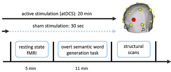 Figure 1. Overview of combined tDCS-fMRI experiment. Two functional fMRI scans were acquired (a resting-state scan followed by a semantic word-generation task). Stimulation (sham or atDCS) started approximately 1-2 min prior to the resting-state scan and commenced until the end of the language task (atDCS), or was ramped down prior to the start of the resting-state scan (sham; not described here; for details see Meinzer et al.14,15). Additional structural scans were acquired after the end of the stimulation. Stimulation location (IFG, red dot in schematic) was determined using the EEG 10-20 system (yellow). Please click here to view a larger version of this figure.
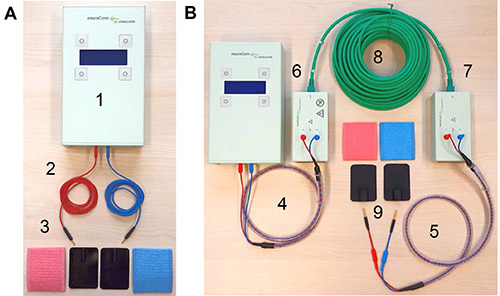 Figure 2. tDCS equipment. (A) Shows standard equipment for a tDCS study. This includes (1) the stimulator, (2) two standard electrode cables, and (3) rubber electrodes and sponge pockets for electrodes. (B) Illustrates additional components required for intrascanner tDCS: (4) stimulator cable, (5) electrode cable equipped with resistors, (6) outer and (7) inner filter boxes, (8) box cable to connect the two filter boxes, and (9) MRI-compatible rubber electrodes. Please click here to view a larger version of this figure.
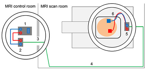 Figure 3. Schematic overview of tDCS set-up outside and inside of the scanner. Direct current stimulator (1) is connected with outer filter box using stimulator cable (2). Box cable enters scanner room through radio frequency filter tube (3). Box cable should be aligned with the wall of the MRI scan room (4) and connected to inner filter box that is positioned inside the MRI scanner (5). Electrodes are attached to the head of the subject and electrode cable is fed through the lower left part of the head coil and connected with the inner filter box (6). Please click here to view a larger version of this figure.
 Figure 4. Details of set-up inside of the scanner. (A) Shows placement of outer filter box in the vicinity of the radio frequency filter tubes and box cable that is inserted into the left filter tube. (B) Close-up of outer box that is not MRI-compatible. Please click here to view a larger version of this figure.
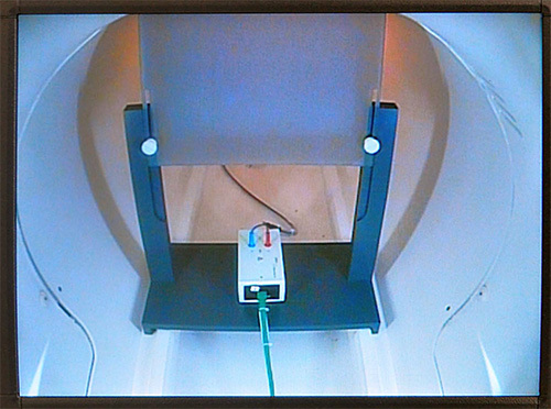 Figure 5. Placement of inner filter box. This figure illustrates the position of inner filter box inside of the scanner (rear end). Filter box is placed underneath a screen on which experimental stimuli are presented using a projector. Please click here to view a larger version of this figure.
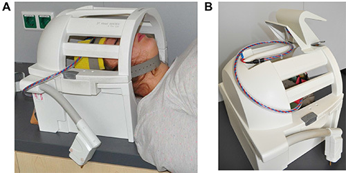 Figure 6. Placement of electrode cable. This figure shows the closed head coil of the scanner. (A) The subject’s head is positioned in head coil with the electrodes attached to the head with rubber electrodes. Electrode cable exits head coil at the lower left side. (B) Electrode is placed on top of the head coil when moving the subject into the scanner bore. Please click here to view a larger version of this figure.
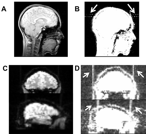 Figure 7. Illustrates high-frequency artifacts induced by a broken cable. (A) Artifact is not visible on axial slice of the localizer scan using the standard contrast in MRIcron (www.mrico.com). (B) Artifact becomes visible after adjusting the contrast settings (white arrows, contrast settings 0-20). Similarly, high-frequency artifact is not visible in functional imaging sequence using default contrast (C), but becomes visible after adjusting contrast (D). Please click here to view a larger version of this figure.
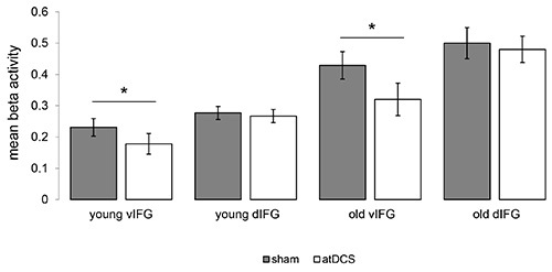 Figure 8. Impact of atDCS on task-related functional activity. Illustrates significant reductions of task-related activity during the semantic word-generation task in the ventral portion of the inferior frontal gyrus (vIFG) in younger and older adults (atDCS < sham, both p<0.05). No significant differences were found in the left dorsal IFG (dIFG) in both groups. Please click here to view a larger version of this figure.
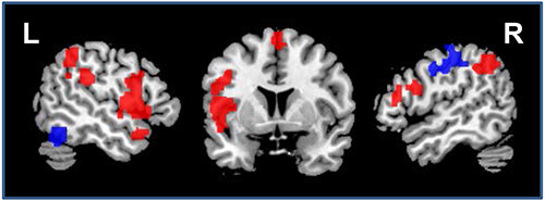 Figure 9. Impact of atDCS on resting-state functional connectivity. Illustrates regions that showed enhanced (red) or reduced (blue) connectivity during atDCS compared to sham stimulation during the resting-state scan (sagittal slices x=-52/52, coronal slice z=5). L=Left hemisphere, R=Right hemisphere. Please click here to view a larger version of this figure.
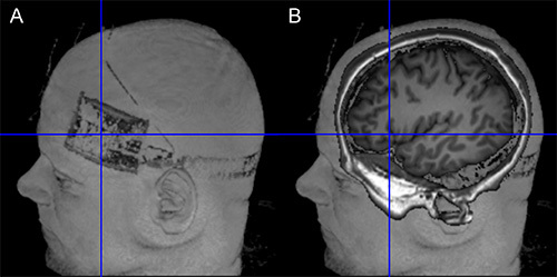 Figure 10. Verification of target position. (A) The left side of the figure shows the location of the electrode on the scalp (Surface rendering based on T1-weighted image using MRIcron). (B) The right side of the image illustrates the projection of the electrode center into the brain of the same subject. Orientation of image is identical in both images. Please click here to view a larger version of this figure.
Discussion
The combined application of tDCS with simultaneous fMRI has shown potential for elucidating the neural underpinnings of the immediate effects of the stimulation across the entire brain with high spatial resolution13-19. In the future, such studies may be complemented by combined EEG-tDCS studies, to exploit the superior temporal resolution of the latter technique. In addition, intrascanner stimulation allows verification of correct positioning of the electrodes on the scalp (e.g. using T-weighted images, see Figure 10). This can help to reduce unwanted variance in experimental studies due to incorrect electrode placement.
Safety for intrascanner stimulation has been established and with appropriate setup, no heat is induced underneath the electrodes (e.g. Holland et al.17, see supplementary materials of this study). The stimulation only minimally affects image quality. For example, tDCS may induce slightly reduced signal-to-noise ratio and susceptibility artifacts or B0 field distortions underneath the electrodes17,18, with the latter restricted to the scalp (for review see Saiote et al.23). However, as well as scalp artifacts, a post-mortem study by Antal et al.29 found tDCS-induced artifacts with comparable magnitude of physiological BOLD effects during a finger tapping task in the ventricles. Therefore, researchers are advised to conduct appropriate image quality assurance procedures23. Moreover, equipment malfunction (e.g. broken connection or electrode cables) may induce high frequency artifacts in BOLD sequences (see Figures 7C and 7D). Therefore, particular care should be taken when handling equipment and prescanning quality assurance procedures. Replacement of broken cables can prevent such artifacts.
In the current protocol, the combined use of tDCS with two fMRI sequences was described. To avoid possible interactions between task-related fMRI effects on subsequent fMRI sequences, and particularly RS-fMRI30, the RS-fMRI was acquired prior to the semantic word-generation task. Moreover, additional structural sequences (e.g. T1, T2, and diffusion weighted scans) were acquired after the functional sequences because the saline soaked sponge electrodes may dry out over time and the stimulation may be compromised if intrascanner tDCS is administered at the end of a longer scanning session.
Aside from the use in experimental settings in healthy participants, future applications of this novel technique are conceivable in patient populations. For example, the combination of tDCS with language treatment administered over several consecutive days has been shown to enhance treatment outcome in post-stroke language disorders (aphasia)31,32. However, while stimulation effects were significant across groups of patients, up to 30% of individual patients did not benefit from the stimulation32. The combined use of tDCS with fMRI may in the future allow identification of patients that respond favorably to a given type of stimulation and help identify patients that do not show these effects. Such studies are a prerequisite for enhancing the effectiveness of future clinical trials that combine behavioral intervention with tDCS. Other applications may include evaluation of the neural underpinnings of beneficial tDCS-effects in dementia and its precursors or other neurological or psychiatric disease3.
Disclosures
The authors have nothing to disclose.
Acknowledgments
This work was supported by grants from the Deutsche Forschungsgemeinschaft (AF: 379-8/1; 379-10/1, 379-11/1 and by DFG-Exc-257, UL: 423/1-1), the Bundesministerium für Bildung und Forschung (AF: FKZ0315673A and 01GY1144; AF and MM: 01EO0801), the German Academic Exchange Service (AF: DAAD-54391829), Go8 Australia - Germany Joint Research Cooperation Scheme (DC: 2011001430), the Else-Kröner Fresenius Stiftung (AF: 2009-141; RL: 2011-119) and the Australian Research Council (DC: ARC FT100100976; MM: ARC FT120100608). We thank Kate Riggall for editorial assistance.
References
- Stagg CJ, Nitsche MA. Physiological basis of transcranial direct current stimulation. Neuroscientist. 2011;17:37–53. doi: 10.1177/1073858410386614. [DOI] [PubMed] [Google Scholar]
- Nitsche M, Paulus W. Sustained excitability elevations induced by transcranial DC motor cortex stimulation in humans. Neurology. 2001;57:1899–1901. doi: 10.1212/wnl.57.10.1899. [DOI] [PubMed] [Google Scholar]
- Flöel A. tDCS-enhanced motor and cognitive function in neurological diseases. NeuroImage. 2014;85:934–947. doi: 10.1016/j.neuroimage.2013.05.098. [DOI] [PubMed] [Google Scholar]
- Brunoni AR, et al. A systematic review on reporting and assessment of adverse effects associated with transcranial direct current stimulation. Int. J. Neuropsychopharmacol. 2011;14:1133–1145. doi: 10.1017/S1461145710001690. [DOI] [PubMed] [Google Scholar]
- Gandiga PC, Hummel FC, Cohen LG. Transcranial DC stimulation (tDCS): a tool for double-blind sham-controlled clinical studies in brain stimulation. Clin. Neurophysiol. 2006;117:845–850. doi: 10.1016/j.clinph.2005.12.003. [DOI] [PubMed] [Google Scholar]
- Jacobson L, Koslowsky M, Lavidor M. tDCS polarity effects in motor and cognitive domains: a meta-analytical review. Exp. Brain Res. 2012;216:1–10. doi: 10.1007/s00221-011-2891-9. [DOI] [PubMed] [Google Scholar]
- Kuo MF, Nitsche MA. Effects of transcranial electrical stimulation on cognition. Clin. EEG Neurosci. 2012;43:192–199. doi: 10.1177/1550059412444975. [DOI] [PubMed] [Google Scholar]
- Reis J, et al. Noninvasive cortical stimulation enhances motor skill acquisition over multiple days through an effect on consolidation. Proc. Natl. Acad. Sci. U.S.A. 2009;106:1590–1595. doi: 10.1073/pnas.0805413106. [DOI] [PMC free article] [PubMed] [Google Scholar]
- Meinzer M, et al. Transcranial direct current stimulation over multiple days improves learning and maintenance of a novel vocabulary. Cortex. 2014;50:137–147. doi: 10.1016/j.cortex.2013.07.013. [DOI] [PubMed] [Google Scholar]
- Cohen Kadosh R, Soskic S, Iuculano T, Kanai R, Walsh V. Modulating neuronal activity produces specific and long-lasting changes in numerical competence. Curr. Biol. 2010;20:2016–2020. doi: 10.1016/j.cub.2010.10.007. [DOI] [PMC free article] [PubMed] [Google Scholar]
- Crosson B, et al. Functional imaging and related techniques: an introduction for rehabilitation researchers. J. Rehabil. Res. Dev. 2010;47 doi: 10.1682/jrrd.2010.02.0017. [DOI] [PMC free article] [PubMed] [Google Scholar]
- Schestatsky P, Morales-Quezada L, Fregni F. Simultaneous EEG monitoring during transcranial direct current stimulation. J. Vis. Exp. 2013. [DOI] [PMC free article] [PubMed]
- Zheng X, Alsop DC, Schlaug G. Effects of transcranial direct current stimulation (tDCS) on human regional cerebral blood flow. NeuroImage. 2011;58:26–33. doi: 10.1016/j.neuroimage.2011.06.018. [DOI] [PMC free article] [PubMed] [Google Scholar]
- Meinzer M, Lindenberg R, Antonenko D, Flaisch T, Flöel A. Anodal transcranial direct current stimulation temporarily reverses age-associated cognitive decline and functional brain activity changes. J. Neurosci. 2013;33:12470–12478. doi: 10.1523/JNEUROSCI.5743-12.2013. [DOI] [PMC free article] [PubMed] [Google Scholar]
- Meinzer M, et al. Electrical brain stimulation improves cognitive performance by modulating functional connectivity and task-specific activation. J. Neurosci. 2012;32:1859–1866. doi: 10.1523/JNEUROSCI.4812-11.2012. [DOI] [PMC free article] [PubMed] [Google Scholar]
- Lindenberg R, Nachtigall L, Meinzer M, Sieg MM, Floel A. Differential effects of dual and unihemispheric motor cortex stimulation in older adults. J. Neurosci. 2013;33:9176–9183. doi: 10.1523/JNEUROSCI.0055-13.2013. [DOI] [PMC free article] [PubMed] [Google Scholar]
- Holland R, et al. Speech facilitation by left inferior frontal cortex stimulation. Curr. Biol. 2011;21:1403–1407. doi: 10.1016/j.cub.2011.07.021. [DOI] [PMC free article] [PubMed] [Google Scholar]
- Antal A, Polania R, Schmidt-Samoa C, Dechent P, Paulus W. Transcranial direct current stimulation over the primary motor cortex during fMRI. NeuroImage. 2011;55:590–596. doi: 10.1016/j.neuroimage.2010.11.085. [DOI] [PubMed] [Google Scholar]
- Stagg CJ, et al. Widespread modulation of cerebral perfusion induced during and after transcranial direct current stimulation applied to the left dorsolateral prefrontal cortex. J. Neurosci. 2013;33:11425–11431. doi: 10.1523/JNEUROSCI.3887-12.2013. [DOI] [PMC free article] [PubMed] [Google Scholar]
- Villamar MF, et al. Technique and considerations in the use of 4x1 ring high-definition transcranial direct current stimulation (HD-tDCS) J. Vis. Exp. 2013. [DOI] [PMC free article] [PubMed]
- DaSilva AF, Volz MS, Bikson M, Fregni F. Electrode positioning and montage in transcranial direct current stimulation. J. Vis. Exp. 2011. [DOI] [PMC free article] [PubMed]
- Turi Z, Paulus W, Antal A. Functional neuroimaging and transcranial electrical stimulation. Clin. EEG Neurosci. 2012;43:200–208. doi: 10.1177/1550059412444978. [DOI] [PubMed] [Google Scholar]
- Saiote C, Turi Z, Paulus W, Antal A. Combining functional magnetic resonance imaging with transcranial electrical stimulation. Front. Hum. Neurosci. 2013;7 doi: 10.3389/fnhum.2013.00435. [DOI] [PMC free article] [PubMed] [Google Scholar]
- Antal A, et al. Direct current stimulation over MT+/V5 modulates motion aftereffect in humans. Neuroreport. 2004;15:2491–2494. doi: 10.1097/00001756-200411150-00012. [DOI] [PubMed] [Google Scholar]
- Meinzer M, et al. Impact of changed positive and negative task-related brain activity on word-retrieval in aging. Neurobiol. Aging. 2012;33:656–669. doi: 10.1016/j.neurobiolaging.2010.06.020. [DOI] [PMC free article] [PubMed] [Google Scholar]
- Meinzer M, et al. Neural signatures of semantic and phonemic fluency in young and old adults. J. Cogn. Neurosci. 2009;21:2007–2018. doi: 10.1162/jocn.2009.21219. [DOI] [PMC free article] [PubMed] [Google Scholar]
- Meinzer M, et al. Same modulation but different starting points: performance modulates age differences in inferior frontal cortex activity during word-retrieval. PloS One. 2012;7 doi: 10.1371/journal.pone.0033631. [DOI] [PMC free article] [PubMed] [Google Scholar]
- Crosson B, Garcia A, McGregor K, Wierenga CE, Meinzer M. In: Neuropsychology Science and Practice. Koffler S, Morgan J, Baron IS, Greiffenstein MF, editors. Oxford University Press; 2013. pp. 149–188. [Google Scholar]
- Antal A, et al. Imaging artifacts induced by electrical stimulation during conventional fMRI of the brain. NeuroImage. 2012. [DOI] [PMC free article] [PubMed]
- Antal A, Terney D, Poreisz C, Paulus W. Towards unravelling task-related modulations of neuroplastic changes induced in the human motor cortex. Eur. J. Neurosci. 2007;26:2687–2691. doi: 10.1111/j.1460-9568.2007.05896.x. [DOI] [PubMed] [Google Scholar]
- Floel A, et al. Short-term anomia training and electrical brain stimulation. Stroke. 2011;42:2065–2067. doi: 10.1161/STROKEAHA.110.609032. [DOI] [PubMed] [Google Scholar]
- Baker JM, Rorden C, Fridriksson J. Using transcranial direct-current stimulation to treat stroke patients with aphasia. Stroke. 2010;41:1229–1236. doi: 10.1161/STROKEAHA.109.576785. [DOI] [PMC free article] [PubMed] [Google Scholar]


