

Abstract
Ultrasound (US) and photoacoustic (PA) multimodality imaging has the advantage of combining good acoustic resolution with high optical contrast. The use of an all-optical scanhead for both imaging modalities can simplify integration of the two systems and miniaturize the imaging scanhead. Herein we propose and demonstrate an all-optical US/PA scanhead using a thin plate for optoacoustic generation in US imaging, a polymer microring resonator for acoustic detection, and a dichroic filter to switch between the two imaging modes by changing the laser wavelength. A synthetic-aperture focusing technique is used to improve the resolution and contrast. Phantom images demonstrate the feasibility of this design, and show that axial and lateral resolutions of 125 μm and 2.52°, respectively, are possible.
Keywords: Ultrasound, Photoacoustic imaging, All-optical scanhead, Dichroic filtering
1. Introduction
Ultrasound (US) imaging based on acoustic scattering and reflection can provide structural details of objects of interest, while photoacoustic (PA) imaging forms an image based on the optical absorption. High resolution and high-frame-rate imaging with high-frequency array is much desired in applications of dermatology [1], ophthalmology [2], intravascular imaging [3], and small animal imaging [4]. State-of-art piezoelectric transducers including high frequency ultrasound arrays and miniaturized single-element transducers for US and PA imaging are currently commercially available. However, for certain clinical applications such as interventional imaging (e.g., endoscopic and intravascular imaging), a miniaturized high-density array is needed for 2-D or even 3-D real-time imaging. It is technically challenging to use piezoelectric materials due to difficulties in dicing array elements smaller than 100 μm, electrical interconnections to individual elements, and avoiding electrical crosstalk. Although there has been significant progress in high-frequency piezoelectric array, it is still difficult to produce high-density array [5]. A high-frequency, 2-D array poses even great challenges. On the other hand, all-optical scanhead is an attractive alternative and has the potential as a high-density array for US and PA imaging.
Optical-based US [6–8] and PA [9–11] transducers can simplify and miniaturize configuration of the imaging scanhead. In this device, acoustic waves can be triggered without any high voltage stimulation so the scanhead can be achieved without any electrical safety concerns. This is especially suitable for interventional imaging use. Also, there is electrical crosstalk between high-density piezoelectrical elements, but less so with an all-optical scanhead. In addition, this all-optical design, which is composed of optical generation and detection of US, has the potential to be made into a small array transducer for interventional imaging.
Optical generation of US [12,13] is a technique involving the generation of acoustic waves based on the PA effect. Characteristics of optically generated ultrasound, including center frequency and bandwidth, can be adjusted with different absorbing films. It can provide a wider bandwidth and thus better axial resolution [12,13]. Conventional optics and scanning systems can achieve element size and spacing on the order of several microns, suitable for synthetic aperture imaging at frequencies exceeding 50 MHz. There is no need to dice the piezoelectric materials or make thousands of electrical connections as the array element is defined by the focus of a scanned laser beam [12,13]. In addition, the technique of detecting US using a resonance optical US transducer has been developed for several decades. There is no trade-off between the size and the sensitivity of elements for an optical detection device (e.g., polymer microring resonator), which means that it has a sensitivity advantage over conventional piezoelectric transducers when small devices are required [14–16]. The polymer microring resonator, composed of a ring and a linear waveguide, is one such optical device for detecting US signals. Acoustic pressure can be used to change the cross-section and strain of the ring waveguide, which is an optical cavity, therefore causing a change in the effective refractive index and a shift in the resonance wavelength. The acoustic waveform can be recovered by detecting the optical output intensity of the bus waveguide at a fixed laser wavelength [14,15]. The microring resonator has several advantages, including being small and having a wide detection bandwidth, adequate SNR, and no requirement for complicated back-end circuitry. These merits make it an excellent candidate for miniaturized imaging scanhead, even for high frequency receiving array.
Synthetic focusing is needed with such an imaging scheme [16]. The synthetic-aperture focusing technique (SAFT) is a well-known method for improving the lateral resolution and contrast of a US image. In the present study it was implemented in the time domain using standard delay-and-sum operations for receive focusing. The signals from different transducer positions are combined to retrospectively synthesize an effective array. For the 1-D SAFT, the signals are delayed to a prespecified reference point and subsequently summed coherently:
| (1) |
where denotes the signal after the SAFT algorithm is applied at each pixel, corresponds to the received A-line signal at position , is the time delay from the synthetic array position to the reference point, and N is the number of scan lines.
We have previously designed and demonstrated an all-optical US/PA scanhead that can acquire US and PA signals simultaneously [17]. However, it is challenging to efficiently separate the two signals. Herein we propose using an all-optical scanhead with a dichroic design to acquire the respective US and PA images.
A dichroic filter is a color filter that can selectively transmit light within a certain frequency range while rejecting light of wavelengths in other bands. The laser light with a specific wavelength can be absorbed by the dichroic filter and thereby induce an acoustic wave that can serve as a US transmitter, while other frequency components can pass through the filter and illuminate the object directly to induce a PA signal in the object. Both signals are received by the polymer microring resonator, which makes the complete scanhead an all-optical device. The dual-modality imaging scanhead can be simplified because we only need to switch laser wavelength to switch imaging modes. In vitro experiments involving a wire and a cyst-like phantom were performed to demonstrate the feasibility of the all-optical US/PA scanhead. In addition, the SAFT was applied to the US and PA images to improve the image resolution and contrast.
2. Methods and system configuration
2.1. Designs of the all-optical US/PA scanhead
As shown in Fig. 1, in our all-optical design the excitation wavelength of the illumination from the bottom selects which imaging mode is used: US or PA. A green laser pulse is absorbed by the red dichroic filter (Edmund Optics, Singapore) to induce an acoustic wave for US transmission, as shown in Fig. 1(a). The echo returned from the imaging object is received by the microring device, which is an optical-based US sensor. On the other hand, the red laser light passes through the dichroic filter and illuminates the sample directly for PA imaging, as shown in Fig. 1(b). The PA signal is also received by the microring device to form a PA image. In this way the laser wavelength can be used to switch the imaging mode between US and PA imaging.
Fig. 1.

Schematics showing the mechanisms underlying (a) US and (b) PA imaging.
2.2. Experimental setup
The experimental setup for US/PA imaging with the all-optical scanhead is shown in Fig. 2. The microring was located on the dichroic filter, but the location of the optical spot/optical absorption is still side by side with the microring device as shown in Fig. 1, so there was no blockage of light and ultrasound transmission.
Fig. 2.

Experimental setup of the US/PA imaging system with the all-optical scanhead design. MMF, multimode fiber; SMF, single-mode fiber.
The system includes excitation, detection, and scanning parts. In the experiments performed for this study, the excitation part was a dual-wavelength laser system comprising a 532-nm Nd:YAG pulsed laser (LOTIS TII LS-2137, Minsk, Republic of Belarus) and a 750-nm Ti:sapphire laser (CF-125, SOLAR TII, Minsk, Republic of Belarus) for US and PA signal generation, respectively. The pulse repetition rate was 10 Hz, and the laser beam was coupled into a 1-mm multimode optical fiber (BEL22-600, Thorlabs, Newton, NJ, USA; NA = 0.22) to deliver laser energy. The spot size related with a width of ultrasonic transmit element is 600 μm which is the same as the core size of the optical fiber for optical excitation because the optical fiber was attached to the dichroic filter.
The dichroic filter, not a dichroic mirror, used was a longpass filter with up to 90% transmission at 750 nm and approximately 0% transmission at 532 nm. The absorbance was 3.1 and nearly 0 at 532 and 750 nm, respectively. The transmission and absorption spectrums are shown in Fig. 3. The thickness of this plastic filter is 1.5 mm and the acoustic attenuation is 7.61 dB/mm in the filter. The damage threshold of the dichroic filter is about 7.08 mJ/mm2. The 750-nm laser light could pass through the dichroic filter while the 532-nm laser light was absorbed by the filter to generate US optically.
Fig. 3.
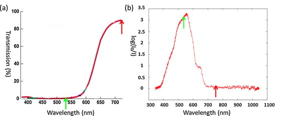
(a) Transmission and (b) optical absorptions of the dichroic filter. The green arrows indicate 532-nm laser light; the red arrows indicate 750-nm laser. I0 and I are the intensity of the incident light and the transmitted light, respectively.
Both the US and PA signals returned from the object are received by the polymer microring resonator, which consisted of a 100-μm-diameter polystyrene ring waveguide closely coupled to a bent-back bus waveguide; this can be fabricated by nanoimprint lithography. The input fiber was connected to another continuous-wave (CW) tunable laser source (TSL-510, Santec, Aichi, Japan), and the output fiber was connected to a high-speed photodetector (1811-FC, New Focus, San Jose, CA, USA) with a gain of 4 × 10⁴ V/A and an electrical bandwidth ranging from 0 to 125 MHz.
The acoustic pressure waveforms of echoed US and PA signals can be recovered from the optical intensity at a specific wavelength [14,15]. A hydrophone (MHA9-150, Force Technology, Denmark) which bandwidth ranging from 0.1 to 80 MHz was used to measure the acoustic field, the center frequency and bandwidth of the scanhead.
The imaging object was mechanically scanned to obtain the full-view image of the object. The scanning was performed with a precision US motor (NR-8, Nanomotion, Yokneam, Israel) controlled by a PC to form a B-mode image. The phantom was 1-D scanned with the step size of 50 μm and the aperture size is 20 mm. The detected US and PA signals were digitized by a 200 M samples/s A/D converter (CompuScope 14200, Gage, Lachine, QC, Canada). Demodulation and synthetic-aperture focusing [18] are applied to improve the image resolution and contrast.
2.3. Signal processing
The radiofrequency signal was digitized by an A/D converter and then simply demodulated with a 10-MHz center frequency to the baseband. The demodulated data from different positions are used to synthesize an array dataset. The receive beam is formed using the conventional delay-and-sum method with the procedure shown in Fig. 4.
Fig. 4.

Schematic of the signal processing.
The imaging performance was evaluated using a wire phantom (Fig. 5(a)) and a cyst-like phantom (Fig. 5(b)). Geometry of the 3-wires phantom is shown in Fig. 5(a). There are three black hairs fixed on a plastic frame. The spatial resolution of the imaging system was estimated by imaging hairs with a diameter of about 100 μm. The axial and lateral resolutions were quantified as the −6-dB widths normalized by the center frequency. A cyst-like phantom with four inclusions, as shown in Fig. 5(b), was constructed from 2% agarose (0710, Amresco, Solon, OH, USA) mixed with 0.8% 106-μm glass beads, which served as acoustic scatterers. Three of the four cysts contained 0.5% graphite powder (282863, Sigma–Aldrich, St. Louis, MO, USA) with the absorbance of 8.58 and the medium of the inclusions is also agarose, the same as the media of the outside region. The fourth cyst was filled with water. In this case, the phantom with graphite powders and glass beads can only simulate the ultrasonic scattering in tissue, but it is not suitable for simulation of optical scattering in tissue. The phantom was scanned with the scanning motor at the step size of 50 μm to prevent grating lobes forming in the images. The radiofrequency signals received by the detector were averaged 32 times and demodulated with a 10-MHz center frequency to the baseband, then processed with the SAFT algorithm.
Fig. 5.

Configurations of (a) the wire phantom and (b) the cyst-like phantom.
The contrast between the graphite region (area 1) and pure agar regions (area 2) was measured as shown in Fig. 5(b) according to
| (2) |
Signals were acquired using the all-optical imaging scanhead, and the SAFT algorithm was applied to implement receive focusing [18]. The image resolution and contrast were compared between before and after applying the SAFT.
3. Results
3.1. Characteristics of generated US signals
The waveform of the generated US signal received by the hydrophone and the corresponding spectrum are shown in Fig. 6. The center frequency and bandwidth of the generated US were 11.3 MHz and 154%, respectively. The spectral characteristics depend on the pulse duration of the laser, and the thickness and optical absorption coefficient of the absorbing film [12,13]. The acoustic field at 3.3 cm from the dichroic filter is shown in Fig. 7. The maximum acoustic pressure was 50 kPa, which can be linearly increased with laser energy below the damage threshold. We measured the pulse energy with an energy meter. The peak-to-peak stability of the pulsed laser is calculated to be 14%.
Fig. 6.

(a) Waveform and (b) frequency spectrum of a typical generated US signal.
Fig. 7.

Acoustic field at 3.3 cm from the dichroic filter.
3.2. Evaluation of imaging resolution and contrast
The US images of the wire and cyst phantom before and after applying the SAFT are shown in Fig. 8. The spatial resolution and contrast values are listed in Table 1. The ultrasonic image of the 3-wires phantom (Fig. 8(a) and (b)) shows the cross-section of the 3 wires and the plastic frame (the left and the right side in the image are the echo signals from the plastic frame). The three yellow arrows in Fig. 8(b) indicate the wires and the two red arrows indicate the echo signals from the plastic frame. There are artifacts due to the multiple reflections from the plastic frame. Fig. 8(a) and (c) respectively shows a US image of the wire phantom and the magnified image of the hair indicated by the yellow arrow before applying the SAFT. The corresponding images of the wire phantom after applying the SAFT are shown in Fig. 8(b) and (d), respectively. The axial and lateral resolutions measured at −6 dB were 125 μm and 2.52° after applying the SAFT. The axial resolution is close to the wavelength of the generated US. Fig. 8(e) shows the cyst phantom image before applying the SAFT. Applying the SAFT enhanced the contrast between the graphite region (yellow box) and the agarose region (red box) by about 5 dB. This shows that the SAFT is effective at improving the imaging resolution and contrast.
Fig. 8.
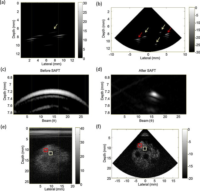
Results for the wire phantom. An improvement in the lateral resolution is clearly evident by comparing the images for before (a) and after (b) applying the SAFT. Magnified images of (a) and (b) are shown in (c) and (d), respectively. The third row shows US images of the cyst-like phantom before (e) and after (f) applying the SAFT. The yellow and red boxes indicate the graphite (area 1) and agarose (area 2) regions, respectively.
Table 1.
Spatial resolution and contrast before and after SAFT processing.
| Before SAFT | After SAFT | |
|---|---|---|
| Axial resolution (μm) | 206 | 125 |
| Lateral resolution (°) | 16.62 | 2.52 |
| Contrast (dB) | 9.53 | 14.54 |
3.3. US/PA imaging of the cyst phantom
US and PA images of the cyst phantom are shown in Fig. 9. The US image (Fig. 9(a)) provides structural information while the PA image (Fig. 9(b)) provides optical contrast. The diameter of graphite powder (dgraphite) is much smaller than the wavelength of the generated acoustic wave (λ). When dgraphite ≪ λ, the scattering cross section of the graphite powder is lower than that of the glass beads (dbeads ∼ λ). Therefore, the inclusions with graphite are hypoechoic in the ultrasound image. The graphite and water regions are both hypoechoic in the US image (Fig. 9(a)), but they can be easily differentiated by the PA contrast (Fig. 9(b)). The artifacts in Fig. 9 occurred due to multiple reflections of the generated acoustic waves inside the dichroic filter, and then these reflected acoustic waves are received by the microring directly without passing through the imaging targets. This artifact also appears in Fig. 8(a).
Fig. 9.

US (a), PA (b) and fusion (c) images of the cyst-like phantom.
4. Discussion
The use of an all-optical scanhead can simplify integration of the US/PA imaging systems without the alignment and registration problem, and miniaturize the imaging scanhead. In addition, the proposed approach can be a cost-effective solution for imaging where a disposable scanhead is needed for one-time use. It is also relatively easy to control size and position of the optically generated ultrasound for a synthetic high-density array. Also, there is no trade-off between the size and sensitivity of elements for a microring device, which means that it has a sensitivity advantage over conventional piezoelectric transducers when small devices are required. Therefore, this design potentially can provide several advantages over conventional designs.
The proposed all-optical scanhead could be constructed as a high-density 2-D array because of the merits of optical generation and detection of ultrasound. The center frequency of generated US in the current design was 11.5 MHz. The key component in optical generation of US is a thin film exhibiting optical absorption. The center frequency of the generated US depends on the laser pulse duration, and the thickness and optical absorption characteristics of the absorbing film. Several research groups have explored the use of various thin films – such as PDMS with carbon black [12] and a nanostructure [13] – to optically generate high-frequency (over 50 MHz) and high-amplitude US (∼800 kPa). Further exploration of alternative thin films is necessary to improve the performance of the all-optical US/PA scanhead.
The current design demonstrated that receive focusing can be achieved by the SAFT; however, transmit focusing is not performed. A PA concave transmitter consisting of an optical absorption film coated on a concave spherical structure [19] could be a candidate for generating focused US in order to further improve the resolution.
The maximum acoustic pressure in this experiment was 50 kPa. Compared with commercial small piezoelectric transducer (e.g., those for intravascular imaging), the acoustic pressure generated by the filter in the current study is lower due to acoustic attenuation in the filter (7.61 dB/mm), and acoustic impedance mismatch between the filter and the medium. The optical absorption depth of the color filter was estimated to be about 1 mm, which means that more than 0.5 mm does not contribute to the source at all, but simply attenuates acoustic waves. Therefore, we can reduce the thickness, select a filter with a higher optical absorption coefficient and add matching layers on the surface of the dichroic filter for improved optical generation of ultrasound. In other word, the acoustic pressure can be increased by using more efficient photoacoustic materials. Stronger acoustic pressure (∼800 kPa) generated by the optical absorption of a mixture of carbon black and PDMS [2] was reported in the literature and which was comparable with other technology for ultrasound transmission. To increase acoustic pressure for ultrasound transmission, materials with higher optical absorption and efficient wavelength selection need to be used.
The major component of the scanhead is the microring device. The size of our current detection setup is 3.5 mm. Nonetheless, this is the size of the substrate, the microring itself is only about 100 μm which is smaller than a single element IVUS transducer. We believe that this design has the potential to provide a miniature array for use in endoscopic and intravascular imaging applications.
The step size of the scanning is 50 μm. Totally, there are 400 steps (i.e., 400 ultrasound transmit elements for the synthetic aperture) to cover a 20 mm scan area. The pulse repetition rate of the excitation laser in this experiment is 10 Hz. Even without signal averaging, the acquisition time for one image is 40 s. The imaging frame rate can be sped up by using a high-speed laser. The other approach is to use a wider laser beam for plane wave ultrasound excitation and a microring array for parallel acoustic detection (Fig. 10). This can theoretically achieve a frame rate the same as the laser pulse repetition frequency. The next stage of this research is to extend the current single-element transducer to an array by combining optical scanning on an absorbing thin film as a transmitting array with a microring receiving array [14]. The size of elements and pitches can be controlled by the optical focusing and scanning on an absorbing thin film, even the use of wider beam for a plane wave excitation to increase imaging frame rates. Particularly for parallel acoustic detection using the microring, as shown in Fig. 10, a linear array can be formed by coupling all microrings to a common straight waveguide (single bus). In such a design each microring has a slightly different diameter, giving each element a different resonance frequency. A tunable laser can address each element one at a time by wavelength selection, or a multiwavelength source can be used to probe all elements simultaneously [14]. This configuration can also be extended to a 2-D microring array for high-speed and 3-dimentional imaging as shown in Fig. 10(b).
Fig. 10.

(a) 1-D linear array and (b) 2-D array all-optical US/PA scanhead designs.
5. Conclusions
This study has demonstrated the feasibility of a US/PA imaging system with an all-optical scanhead design. The experimental image results indicated that the US and PA imaging modes can be selected by switching the laser wavelengths using a color-selective thin plate. The imaging resolution and contrast were improved by applying the SAFT. The axial and lateral resolutions of the implemented imaging system were 125 μm and 2.52°, respectively, while application of the SAFT enhanced the contrast by about 5 dB.
Conflict of interest
The authors declare that there are no conflicts of interest.
Acknowledgements
Support from the National Science Council (Grant no. NSC 100-2221-E-002-146-MY3) and the NTU Center for Emerging Material and Advanced Devices is greatly appreciated.
Biographies

Bao-Yu Hsieh received the B.S. degree in Department of Biomedical Imaging and Radiological Sciences and the M.S. degree in Institute of Biophotonics from National Yang-Ming University, Taipei, Taiwan, in 2005 and 2007, and the Ph.D. from the Graduate Institute of Biomedical Electronics and Bioinformatics at National Taiwan University, Taipei, Taiwan, in 2012. His research interest is intravascular photoacoustic imaging.

Sung-Liang Chen received his B.S. degree in electrical engineering and M.S. degree in electro-optical engineering from National Taiwan University, Taipei, Taiwan, in 2003 and 2005, respectively, and Ph.D. degree in electrical engineering from the University of Michigan, Ann Arbor, in 2011. He is currently an assistant professor at the University of Michigan-Shanghai Jiao Tong University Joint Institute, Shanghai, China. His research interests include optical resonators for sensing applications, optical imaging systems, and photoacoustic imaging.

Tao Ling received B.S. degree in physics from Nankai University, China, M.S. degree in optics from Fudan University, China and Ph.D. degree in electrical engineering from the University of Michigan at Ann Arbor, USA. Currently, he is working as a postdoctoral researcher in the University of Michigan at Ann Arbor. His main research interests include photonics and nanotechnology.

L. Jay Guo is a professor of electrical engineering and computer science at the University of Michigan, with joint appointment in mechanical engineering, macomolecular science and engineering, and applied physics. He has over 120 refereed journal publications. His group's researches include polymer-based photonic devices and sensor applications, organic photovoltaics, plasmonic nanophotonics/metamaterials, nanoimprint-based and roll to roll nanomanufacturing technologies. He and his collaborators pioneered the polymer microring resonator as a new photonic platform for highly sensitive detection of broadband ultrasound. He received Ph.D. in electrical engineering from the University of Minnesota in 1997.

Pai-Chi Li received the B.S. degree in electrical engineering from National Taiwan University in 1987, and the M.S. and Ph.D. degrees from the University of Michigan, in 1990 and 1994, respectively, both in electrical engineering: systems. He joined Acuson Corporation, Mountain View, CA, as a member of the technical staff in June 1994. His work in Acuson was primarily in the areas of medical ultrasonic imaging system design for both cardiology and general imaging applications. In August 1997, he went back to the Department of Electrical Engineering at National Taiwan University, where he is currently distinguished professor of Department of Electrical Engineering and Institute of Biomedical Electronics and Bioinformatics. His current research interests include biomedical ultrasound and medical devices.
Footnotes
This is an open-access article distributed under the terms of the Creative Commons Attribution-NonCommercial-ShareAlike License, which permits non-commercial use, distribution, and reproduction in any medium, provided the original author and source are credited.
References
- 1.Turnbull D.H., Starkoski B.G., Harasiewicz K.A., Semple J.L., From L., Gupta A.K. A 40–100 MHz B-scan ultrasound backscatter microscope for skin imaging. Ultrasound Med Biol. 1995;21:79–88. doi: 10.1016/0301-5629(94)00083-2. [DOI] [PubMed] [Google Scholar]
- 2.Foster F.S., Lockwood G.R., Ryan L.K., Harasiewicz K.A., Berube L., Rauth A.M. Principles and applications of ultrasonic backscatter microscopy. IEEE Trans Ultrason Ferroelectr Freq Control. 1993;40:608–616. doi: 10.1109/58.238115. [DOI] [PubMed] [Google Scholar]
- 3.White R.A., Donayre C.E., Kopchok G.E., Walot I., Mehinger C.M., Wilson E.P. Vascular imaging before, during, and after endovascular repair. World J Surg. 1996;20:622–629. doi: 10.1007/s002689900095. [DOI] [PubMed] [Google Scholar]
- 4.Foster F.S., Zhang M.Y., Zhou Y.Q., Liu G., Mehi J., Cherin E. A new ultrasound instrument for in vivo microimaging of mice. Ultrasound Med Biol. 2002;28:1165–1172. doi: 10.1016/s0301-5629(02)00567-7. [DOI] [PubMed] [Google Scholar]
- 5.Cannata J.M., Williams J.A., Zhou Q., Ritter T.A., Shung K.K. Development of 35-MHz piezo-composite ultrasound array for medical imaging. IEEE Trans Ultrason Ferroelectr Freq Control. 2006;53:224–236. doi: 10.1109/tuffc.2006.1588408. [DOI] [PubMed] [Google Scholar]
- 6.Hou Y., Ashkenazi S., Huang S.W., O’Donnell M. An integrated optoacoustic transducer combining etalon and black PDMS structures. IEEE Trans Ultrason Ferroelectr Freq Control. 2008;55:2719–2725. doi: 10.1109/TUFFC.2008.988. [DOI] [PMC free article] [PubMed] [Google Scholar]
- 7.O’Donnell M., Hou Y., Kim J.S., Ashkenazi S., Huang S.W., Guo L.J. Optoacoustic generation of high frequency sound for 3-D ultrasonic imaging in medicine. Eur Phys J Spec Top. 2008;153:53–58. doi: 10.1140/epjst/e2008-00392-9. [DOI] [PMC free article] [PubMed] [Google Scholar]
- 8.Hou Y., Kim J.S., Huang S.W., Ashkenazi S., Guo L.J., O’Donnell M. Characterization of a broadband all-optical ultrasound transducer—from optical and acoustical properties to imaging. IEEE Trans Ultrason Ferroelectr Freq Control. 2008;55:1867–1877. doi: 10.1109/TUFFC.2008.870. [DOI] [PMC free article] [PubMed] [Google Scholar]
- 9.Xie Z., Chen S.L., Ling T., Guo L.J., Carson P.L., Wang X. Pure optical photoacoustic microscopy. Opt Express. 2011;19:9027–9034. doi: 10.1364/OE.19.009027. [DOI] [PMC free article] [PubMed] [Google Scholar]
- 10.Zhang E., Beard P. A miniature all-optical photoacoustic imaging probe. Proc SPIE. 2011;7899:78991F–79001F. [Google Scholar]
- 11.Laufer J., Johnson P., Zhang E., Treeby B., Cox B., Pedley B. In vivo preclinical photoacoustic imaging of tumor vasculature development and therapy. J Biomed Opt. 2012;17:056016. doi: 10.1117/1.JBO.17.5.056016. [DOI] [PubMed] [Google Scholar]
- 12.Buma T., Spisar M., O’Donnell M. High-frequency ultrasound array element using thermoelastic expansion in an elastomeric film. Appl Phys Lett. 2001;79:548–550. [Google Scholar]
- 13.Hou Y., Kim J.S., Ashkenazi S., O’Donnell M., Guo L.J. Optical generation of high frequency ultrasound using two-dimensional gold nanostructure. Appl Phys Lett. 2006;89:093901. [Google Scholar]
- 14.Chao C.Y., Ashkenazi S., Huang S.W., O’Donnell M., Guo L.J. High-frequency ultrasound sensors using polymer microring resonators. IEEE Trans Ultrason Ferroelectr Freq Control. 2007;54:957–965. doi: 10.1109/tuffc.2007.341. [DOI] [PubMed] [Google Scholar]
- 15.Huang S.W., Cheng S.L., Ling T., Maxwell A., O’Donnell M., Guo L.J. Low-noise wideband ultrasound detection using polymer microring resonators. Appl Phys Lett. 2008;92:193509. doi: 10.1063/1.2929379. [DOI] [PMC free article] [PubMed] [Google Scholar]
- 16.Maxwell A., Huang S.W., Ling T., Kim J.S., Ashkenazi S., Guo L.J. Polymer microring resonators for high-frequency ultrasound detection and imaging. IEEE J Sel Top Quantum Electron. 2008;14:191–197. doi: 10.1109/JSTQE.2007.914047. [DOI] [PMC free article] [PubMed] [Google Scholar]
- 17.Hsieh B.Y., Chen S.L., Ling T., Guo L.J., Li P.C. All-optical scanhead for ultrasound and photoacoustic dual-modality imaging. Opt Express. 2012;20:1588–1596. doi: 10.1364/OE.20.001588. [DOI] [PubMed] [Google Scholar]
- 18.Deng Z., Yang X., Gong H., Luo Q. Two-dimensional synthetic-aperature focusing technique in photoacoustic microscopy. J Appl Phys. 2011;109:104701. [Google Scholar]
- 19.Baac H.W., Ling T., Ashkenazi A., Huang S.W., Guo L.J. Photo-acoustic concave transmitter for generating high frequency focused ultrasound. Proc Soc Photo-Opt Instrum Eng. 2010;7564:75642M. doi: 10.1117/12.841089. [DOI] [PMC free article] [PubMed] [Google Scholar]