Abstract
A high-throughput on-chip imaging platform that can rapidly monitor and characterize various cell types within a heterogeneous solution over a depth-of-field of 4 mm and a field-of-view of ~10 cm2 is introduced. This powerful system can rapidly image/monitor multiple layers of cells, within a volume of ~4 mL all in parallel without the need for any lenses, microscope-objectives or any mechanical scanning. In this high-throughput lensless imaging scheme, the classical diffraction pattern (i.e., the shadow) of each micro-particle within the entire sample volume is detected in less than a second using an opto-electronic sensor chip. The acquired shadow image is then digitally processed using a custom developed “decision algorithm” to enable both the identification of the particle location in 3D and the characterization of each micro-particle type within the sample volume. Through experimental results, we show that different cell types (e.g., red blood cells, fibroblasts, etc.) or other micro-particles all exhibit uniquely different shadow patterns and therefore can be rapidly identified without any ambiguity using the developed decision algorithm, enabling high-throughput characterization of a heterogeneous solution. This lensfree on chip cell imaging platform shows a significant promise especially for medical diagnostic applications relevant to global health problems, where compact and cost-effective diagnostic tools are urgently needed in resource limited settings.
Keywords: on-chip imaging, lensfree—lensless imaging, high-throughput cytometry, cell counting, point-of-care devices, global health
Introduction
Rapid and high-throughput counting and characterization of different cell types within a heterogeneous mixture is a challenging, but an important task for various applications in bioengineering and medicine. In clinical settings, the cell count measurements are mostly performed by using flowcytometry, which is expensive, complex and bulky (Burger and Gershman, 1988; Darzynkiewicz et al., 1999; Hulett et al., 1973; Kamentsky et al. 1997). Furthermore, the characterization speed of most flow-cytometers is practically less than 10,000 cells/s, which sets a certain limit on their use towards high-throughput screening. There have been various studies to miniaturize conventional bench-top flow-cytometers into portable units. However, rather than increasing the throughput, these efforts have been mostly focused on developing techniques that can provide higher detection efficiency, reduced size, or reduced stress to vulnerable cells (Kamei et al., 2003; Lancaster et al., 2005; Niehren et al., 1995; Novak et al., 2007; Wolff et al., 2003). For instance, a rapid electro-osmotic micro pump in a vertical channel only allows a controlled flow speed of 120 cells/min (Joo et al., 2007). Furthermore, most of such micro-cytometers that used charged coupled device (CCD) or complementary field oxide semiconductor (CMOS) cameras for optical detection were limited to a flow rate of less than 100 cells/sec, which is significantly slower than conventional flow-cytometry (Lien et al., 2005). In the meantime, for point-of-care applications, there is an urgent need for a compact, cost-effective and high-throughput cell counting/imaging device that can possibly work even at resource limited settings, with minimum amount of training (Cheng et al., 2005, 2007; Chin et al., 2006; Macnab and Koshland, 1972; Lee, 2003; Ozcan et al., 2007).
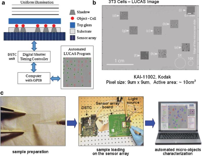
For high-throughput cell counting or monitoring applications, a high resolution optical microscope (see e.g., Ozcan, 2006; Steinberg and Ali, 2001; Weinstein et al., 2004) is not always necessary. The most relevant information that a high-throughput cell characterization system should provide is the type and the count of the cells of interest within the sample volume. Recently, we proposed an imaging platform termed “Lensless, Ultra wide-field Cell monitoring Array platform based on Shadow imaging” (LUCAS), which relies on recording the shadow image of each individual cell onto an optoelectronic sensor array plane (Ozcan and Demirci, 2007). In LUCAS, the cells of interest are positioned on a microscope slide or within a microfluidic device, and are uniformly illuminated with a regular incoherent white-light source. After a diffraction limited propagation of for example, 0.1–0.2 mm through the bottom substrate, the shadow pattern of each cell is digitally recorded using a sensor array such as a charge-coupled device (CCD) as shown in Figure 1a.
Figure 1.
a: Experimental LUCAS set-up illustrating the effect of diffraction on the cell shadow; (b) Single frame LUCAS image for 3T3 cells that is captured using the set-up of (a) over an ultra-wide field of view of ~10 cm2. The insets show the zoomed images of various points on the LUCAS image illustrating the diffraction signatures of individual 3T3 cells. The same figure with white dashed circles also shows the field-of-view of 10× and 5× objective-lenses. This figure demonstrates that LUCAS can monitor a field-of-view that is ~2 orders of magnitude wider than a regular optical microscope. c: A brief illustration of LUCAS imaging steps. [Color figure can be seen in the online version of this article, available at www.interscience.wiley.com.]
This initial demonstration of LUCAS could handle a limited sample solution volume of <0.08 mL, and was only applicable to homogenous cell solutions, which can be considered as important limitations. In this manuscript, we significantly expand this previous technique in two major aspects:
We experimentally illustrate that the same LUCAS platform can significantly be improved to enable unique identification and characterization of various cell types or other microscopic particles within a heterogeneous cell mixture using a custom-developed “decision algorithm”. This novel algorithm processes the unique diffraction pattern corresponding to each micro-particle/cell to identify its type and its three-dimensional location within the sample volume.
We also significantly improve the depth-of-field and the sample volume that can be monitored using LUCAS. Specifically, we illustrate that, unlike a conventional optical microscope, the LUCAS platform can monitor and characterize cells/micro-particles over an ultra-large depth-of-field of ~4 mm without the need for refocusing. Combined with its ultra-wide field-of-view of ~10 cm2, this implies rapid and unambiguous characterization and localization of micro-particles, including cells, within a heterogeneous sample volume of ~4 mL.
Therefore, we can conclude that not only the biological relevance of our previous technique (Ozcan and Demirci, 2007) has been significantly improved by being able to work with a heterogeneous cell mixture through the use of a novel decision algorithm, but also the sample volume that is imaged has been increased by more than 40-fold. This powerful cell imaging platform does not use any lenses or microscope objectives, and therefore offers an extremely compact device volume that can eventually be integrated within a regular cell-phone. Given its compact design and ultra large sample volume, combined with a powerful digital processing interface, this on-chip imaging platform holds great promise for point-of-care diagnostic devices that can be used to rapidly measure the count of for example, red blood cells (RBCs) or T-lymphocytes (such as CD4 cells) from whole blood samples, especially in resource limited settings.
Materials and Methods
Sample Preparation and High-Throughput On Chip Imaging
To illustrate the unique capability of the LUCAS system, Figure 1b shows a single frame LUCAS image for NIH-3T3 cells (fibroblasts; suspended within 1× phosphate buffered saline (PBS) solution, that is, non-adherent to the substrate) that is acquired within less than 1 s using the set-up of Figure 1a over a field of view of ~10 cm2. This raw LUCAS image has a digital size of >20 MB and is composed of >11 million pixels. For this experiment we used a CCD chip with a pixel size of 9 μm × 9μm having an active area of ~10 cm2 (KAI-11002, Kodak, Rochester, NY). The cover glass of the CCD chip was removed to better control the object-to-sensor distance, for example, 100 μm in Figure 1b. The electronic shutter was adjusted to capture one LUCAS frame with ~438 ms integration time, which roughly constitutes half of the image read-out time. Note that since there is no external fluid flow during this integration time window, the diffraction signature of the cells within the solution is not affected. The insets of Figure 1b also show the zoomed images of various points on the LUCAS image illustrating the unique diffraction signatures of individual 3T3 cells. The same figure also shows with white dashed circles the field-of-view of standard 10× and 5× objective-lenses. This figure demonstrates that the LUCAS platform can monitor a field-of-view that is 2 orders of magnitude wider than a regular optical microscope, highlighting its high-throughput nature.
Figure 1c briefly illustrates the on chip imaging process in LUCAS. Initially, the micro-objects (such as cultured cells of interest) are suspended in for example, 1× PBS solution, and this diluted sample solution is placed using a micropipette between two microscope slides or within a liquid reservoir (e.g., a micro-fluidic channel) which has an area of ≤10 cm2. Then, the entire sample (together with the substrate) is positioned onto the active region of the digital sensor array using a vacuum pen (NT57-636, Edmund Optics, Barrington, NJ). Illuminated by a collimated beam of an incoherent light source for example, a monochromator (Oriel Cornerstone™ 260-1/4 m, Newport) or a fiber optic white-light illuminator (DC-950, Dolan-Jenner, Boxborough, MA), the shadow/diffraction signature of each micro-object falls onto the sensor array forming the LUCAS image.
Decision Algorithm
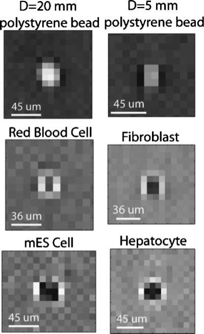
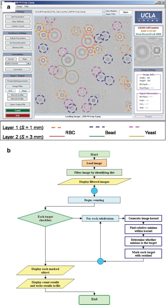
For the development of LUCAS cell identification and characterization algorithm, some of the useful quantitative image metrics, among many others, are the diameter, the 2D texture, and the contrast of the LUCAS shadow image with respect to the background. Figure 2 illustrates the unique diffraction signatures of several cell lines or other micro-particles imaged using LUCAS. The developed decision algorithm functions based on primarily three parameters: (i) A threshold level, which defines the intensity level of the micro-object signature compared to the background noise level; (ii) The width of the target micro-object in terms of number of pixels; and (iii) the 2D correlation of the statistical signature of a target object type with the acquired LUCAS image of interest. These parameters were robust enough to accurately characterize heterogeneous mixtures of various micro-objects such as RBCs, hepatocytes, yeast cells and micro-beads. The user-interface together with a simplified flow-chart of this developed algorithm are illustrated in Figure 3a and b, respectively. We illustrate in the screen-shot image of Figure 3a, computer-based analysis of a LUCAS image for a two-layered heterogeneous mixture of 10 μm beads, RBCs, and yeast cells (S. Pombe). Each layer in this solution is separated by ~2 mm. In this figure, the location and the height of each RBC, yeast cell, and micro-bead is automatically detected using a custom-developed decision algorithm, which matches the unique statistical diffraction signature of any micro-object with the thresholded LUCAS image for identification and localization of each target cell/particle.
Figure 2.
For LUCAS images, the shape and the contrast difference among different cell types and micro-beads is shown. In these lensfree LUCAS images, the contrast is reversed for cells versus micro-particles. Furthermore, each cell type exhibits a characteristic LUCAS signature that permits digital sorting of different cell types from each other within a LUCAS image.
Figure 3.
a: LUCAS characterization results of a two-layered heterogeneous mixture are illustrated. Each layer of the mixture, located at S = 1.0 μm and S = 3.0 mm, contains 10 μm diameter micro-beads, red blood cells, and yeast cells (S. Pombe), all suspended in 1× PBS solution. Different colored solid and dashed circles mark the location and the height of each cell/particle type located within the sample volume—see the figure legend. b: Simplified flow-chart of the decision algorithm is shown. [Color figure can be seen in the online version of this article, available at www.interscience.wiley.com.]
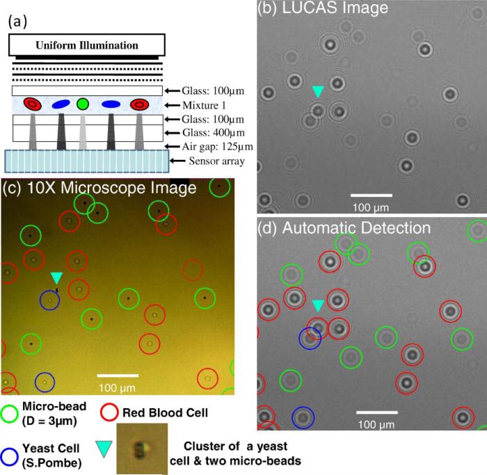
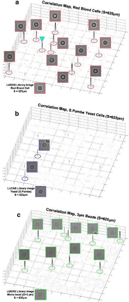
For 2D correlation calculations, the decision algorithm utilizes a set of training LUCAS images corresponding to homogenous populations in order to build a statistical image library for each cell/micro-object type at a given depth-of-field. Using this statistical approach, the effect of the variations in the shadow images of the same cell kind on the accuracy of the counting algorithm can be minimized. To provide an example of how such 2D correlation maps are utilized in LUCAS, in Figure 4 we illustrate the details of LUCAS characterization for a heterogeneous mixture of RBCs, yeast cells (S. Pombe) and 3 μm diameter polystyrene beads imaged at a DOF of S = 625 μm. In Figure 4b, we show a zoomed region of the acquired LUCAS image and its comparison with a regular 10× microscope image (Fig. 4c). Figure 4d shows the output of our decision algorithm, marking with different colored circles each cell/particle type. For comparison purposes the 10× microscope image in Figure 4c also uses the same colored circles for each micro-object. In our characterization results, except the diffraction signature that is pointed with a triangle in Figure 4d, all the characterization decisions are correct, and exactly match with the microscope image. For the triangular spot in Figure 4d, there is actually a cluster of 2 microbeads together with a yeast cell, all touching each other, which forced an error in our decision algorithm as marked in Figure 4d—see the microscope image in Figure 4c. This error is unavoidable in LUCAS since the diffraction pattern of the clustered object is uniquely different than the individual micro-objects making up the cluster. To further provide the details of these characterization results, we show in Figure 5 the 2D correlation maps of each micro-object type that are calculated using the LUCAS library image of the target cell/ particle imaged at the same DOF value of S = 625 μm and under the same illumination conditions. Figure 5 clearly indicates that for RBCs, yeast cells and the 3 μm beads, each 2D correlation map exhibits a strong peak at the locations where the target diffraction signatures reside (compare Fig. 4c and d with Fig. 5). Furthermore, it is worth noting that the LUCAS decision algorithm was quite robust for some of the partially overlapping diffraction signatures: see for example, Fig. 5b and c for individual yeast or 3 μm bead diffraction signatures that were partially overlapping with other diffraction signatures and could still be correctly identified in their corresponding 2D correlation maps.
Figure 4.
a: A LUCAS characterization experiment is illustrated for a heterogeneous mixture of RBCs, yeast cells and 3 μm beads imaged at a DOF of 625 μm. b: LUCAS image showing a zoomed region of interest. c: 10× microscope image of the same FOV that is imaged in (b). d: Automated LUCAS characterization results marking the location of each cell/object type. For comparison purposes the 10× microscope image in (c) also uses the same colored circles for each micro-object type. In our characterization results, except the diffraction signature that is pointed with a triangle in (d), all the characterization decisions are correct, exactly matching with the microscope image. For the triangular spot, there is actually a cluster of two microbeads together with a yeast cell, all touching each other, which forced an error in our decision algorithm as marked in (d). The details of the 2D correlation maps that are used for the decision making are further illustrated in Figure 5 for each cell/micro-object type. [Color figure can be seen in the online version of this article, available at www.interscience.wiley.com.]
Figure 5.
The 2D correlation maps for RBCs, yeast cells and 3 μm beads are illustrated for the LUCAS experiment shown in Figure 4. Notice in (b and c) that the characterization is accurate even if there is a partial overlap in the diffraction signatures of some of the micro-objects/cells. [Color figure can be seen in the online version of this article, available at www.interscience.wiley.com.]
Due to its ultra-wide FOV of ~10 cm2, this decision algorithm can in principle identify and characterize ~50,000 cells within 1 s over this entire FOV of the LUCAS platform. In general, for a single plane of cells, if there exists M cells within the entire LUCAS field-of-view, and each cell has a shadow diameter of CS, then the percentage of cells that do not overlap can be written as exp(–πM(CS)2/FOV), where FOV (the field-of-view of the LUCAS platform) has been assumed to be large when compared to M(CS)2. This implies that for M = 50,000; CS = 25 μm; and a FOV of ~10 cm2, >90% of the imaged cells will not be overlapping. As a matter of fact, some portion of the remaining ~10% of the “statistically overlapping” cells can still be counted by using powerful segmentation and edge detection algorithms, reducing the statistical error further below 10%. Therefore, the statistical error rate of the automated decision algorithm due to cell overlap probability will not be a limiting factor for less than 50,000 cells over a LUCAS FOV of ~10 cm2.
Our initials studies indicate that the accuracy of our decision algorithm varies based on the mixture of micro-objects to be analyzed. With homogenous mixtures containing only beads, RBCs, fibroblasts, etc. a count accuracy as high as >98% was easily achieved. We also achieved a count accuracy of over ~90% for artificial mixtures of for example, RBCs, hepatocytes or fibroblasts imaged at a DOF of <500 μm. Meanwhile, for heterogeneous solutions imaged at a longer DOF, for example, >2 mm, the characterization results based on the raw LUCAS image can sometimes yield an unacceptable error rate of for example, >30%. To better combat such characterization issues at longer DOF values of >2 mm, use of digital noise reduction filters (e.g., Enhanced Lee Filter (Lee, 1981)) and more complex illuminations schemes using for example, multiple-wavelengths are currently being explored.
Results
Since LUCAS is a lensless system, there is no optical magnification and the spatial resolution of the recorded diffraction signatures is quite poor (i.e., under-sampled). This, however, is not a limitation for LUCAS since the diffraction signatures corresponding to different microscopic objects exhibit uniquely different 2D textures. This characteristic shadow signature of each micro-object type enables automated counting and characterization of various particles/cells within a heterogeneous solution even with highly pixelated low resolution LUCAS images. Our initial results illustrating this unique cell identification/characterization potential of the LUCAS platform are shown in Figure 2 for red blood cells (RBCs), fibroblasts, hepatocytes, mouse embryonic stem cells (mES) and polystyrene micro-beads. First, note that in these lensfree LUCAS diffraction images, the contrast is reversed for micro-beads versus cells, that is, the center of the cell shadow is darker, whereas the center of the bead shadow is brighter with respect to the background. This contrast reversal provides a powerful means for automated separation of cells from other micro-particles found within the same solution. Second, note also that depending on the size of the particle, the strength of this contrast reversal also varies (see e.g., top row of Fig. 2), illustrating the uniqueness of the LUCAS signature of different micro-objects. Third, due to its disk shape, the shadow signature of the RBC shows a uniquely different diffraction pattern (i.e., 2D texture) than other cells or micro-beads. These results illustrate the fact that different cell types (or micro-objects) have uniquely different signatures (i.e., diffraction patterns, shadow shapes, and contrast properties) in their LUCAS images, and this important feature of LUCAS can be utilized by an automated computer algorithm (i.e., the decision algorithm) to characterize a heterogeneous mixture of cells/micro-objects, even if the resolution level of the acquired image is quite coarse (see e.g., Figs. 4 and 5).
As described in the previous section, the ultra-wide field of view of the LUCAS platform stems from the fact that there is no real magnification in LUCAS; and that the diffraction pattern of each micro-particle is under-sampled by a large area sensor array creating a pixilated signature for each micro-particle type. Along these lines, Figures 1–5 illustrate the proof-of-principles of LUCAS and its quantitative comparison to conventional optical microscopy. On the other hand, the exciting potential of LUCAS is not limited only to the above results. Another exciting feature of the LUCAS platform is that it permits monitoring, characterization and three-dimensional localization of different microscopic objects within a much longer depth-of-field (DOF) than a regular wide-field optical microscope would normally permit. Therefore, in LUCAS various layers of micro-objects (such as cells located within a multi-layered microfluidic device; within a stack of microscope slides or within a solution reservoir) can be monitored all in parallel without the need for refocusing. In principle, LUCAS can permit a DOF of ~0.4 cm within which the diffraction signature of each micro-object located at any given plane exhibits a uniquely different pattern.
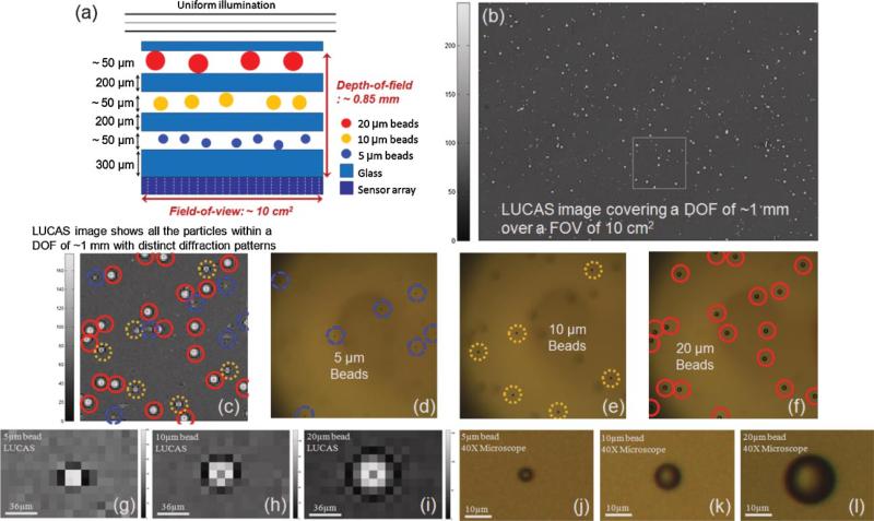
To experimentally verify this claim, we initially prepared polystyrene micro-beads of different sizes (5, 10, and 20 μm in diameter, Duke Scientific, Fremont, CA) diluted in 1× PBS. Then, using the LUCAS system, we imaged a multi-layer structure as shown in Figure 6a. This multi-layered object is composed of three different planes of micro-beads separated by glass slides of a few hundreds of micrometer thicknesses. For this multi-layered object, the total DOF was ~0.85 μm, which is beyond the reach of a conventional optical microscope, that is, mechanical adjustment of the focus of the microscope would normally be needed to monitor all the micro-beads located at different planes. This limitation of conventional optical microscopy (under a 10× objective-lens) is verified in Figure 6d–f, where in each frame only one type of micro-bead (located at a single plane) could be imaged. As a result of its small DOF, three consecutive microscope images were acquired (Fig. 6d–f) using a 10× objective-lens to image all the micro-beads located at different planes within a DOF of ~0.85 μm. On the contrary, with LUCAS, a single lensless image captured the uniquely different diffraction signatures of each type of micro-particle, enabling monitoring and sorting of all the micro-objects within the entire DOF.
Figure 6.
a: A multi-layered object that is composed of 3 planes of micro-beads (5, 10, and 20 μm diameter) over a depth-of-field of ~0.85 mm. b: LUCAS image acquired for the object shown in (a). c: Zoomed version of the LUCAS image taken from the white frame within (b). Each micro-object exhibits a uniquely different diffraction pattern, and the solid red, dotted yellow and dashed blue circles represent 20, 10, and 5 μm diameter beads, respectively. A single LUCAS image, as shown in (b and c), shows all the particles with distinct patterns within a dept-of-field of ~1 mm and over a FOV of 10 cm2. On the other hand, a conventional microscope requires three consecutive images to monitor all these different planes of micro-objects. d–f: Demonstrate three microscope images (taken with a 10× microscope objective) that illustrate the individual planes of the multi-layered object shown in (a). Note that in each one of these microscope images, the other micro-particles are missing due to the limited depth-of-field of the microscope. g–l: The zoomed versions of the LUCAS images and the microscope images (under 40×) corresponding to 5, 10, and 20 μm diameter beads. [Color figure can be seen in the online version of this article, available at www.interscience.wiley.com.]
Figure 6b shows the LUCAS image of this multi-layered object, where the zoomed region (the white frame in Figure 6b) is also highlighted in Figure 6c, illustrating the location of different sized micro-beads with different colored circles. The characteristic diffraction signature of each micro-bead type that is located at a different plane as depicted in Figure 6a is also shown in Figure 6g–i. The comparison of the LUCAS image (Fig. 6c) with three consecutive microscope images (Fig. 6d–f) corresponding to the same region of interest at different image planes verifies the stimulating potential of the LUCAS platform such that various types of micro-particles within a large volume (corresponding to a long DOF and a wide FOV) can be monitored all in parallel.
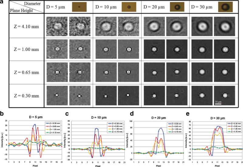
To further investigate the performance of the LUCAS platform for multi-layered objects, we conducted a series of imaging experiments to build a small “shadow signature library” corresponding to diffraction patterns of various micro-objects at different plane heights. Figure 7a shows this shadow signature library for various sized micro-beads (D = 5, 10, 20, and 30 μm) located at different plane heights (S = 0.30, 0.65, 1.00, and 4.10 mm) where D and S refer to the diameter of the micro-beads, and the vertical distance between micro-beads and the sensor array, respectively. Therefore, S = 0 defines the plane of the sensor array. And each entry in Figure 7a has two images corresponding to two different objects of the same diameter value, aimed to demonstrate the uniformity of the acquired shadow signatures for a given micro-particle type. Each column in Figure 7a illustrates that as the height of the micro-particle increases, due to diffraction, its shadow signature spreads. This implies that individual particles that share the same diameter, shape and refractive index can all be localized within a DOF of ~4 mm by simply observing the shadow size at the sensor plane. In other words, the height location of each particle type within the sample volume is uniquely encoded in its shadow width and texture. On the other hand, each row in Figure 7a illustrates that the shadow signature of different types of micro-particles at the same plane height all exhibits similar shadow widths. However, this does not pose a limitation for identification and localization of different types of micro particles located at the same plane. Since the contrast properties and the signal strength of these shadow signatures corresponding to different particle types are all uniquely different than each other, unambiguous identification of each particle type located at the same plane is feasible. Figure 7b–e shows the cross-sectional amplitude variations in LUCAS shadow signatures corresponding to 5, 10, 20, and 30 μm sized beads at different plane heights, respectively. Therefore, the results of Figure 7 indicate that based on the unique size, shape, contrast and the signal strength of the recorded shadow signatures, three-dimensional localization and identification of different micro-particles within a heterogeneous solution is possible with LUCAS.
Figure 7.
a: LUCAS signature library of various micro-beads (D = 5, 10, 20, and 30 μm) located at different planes (S = 0.30, 0.65, 1.00, and 4.10 mm). Each specific entry shows two images to illustrate the uniformity of the acquired shadow signatures. b–e show the cross-sectional amplitude variations in 5 μm (b), 10 μm (c), 20 μm (d) and 30 μm (e) diameter beads, respectively. [Color figure can be seen in the online version of this article, available at www.interscience.wiley.com.]
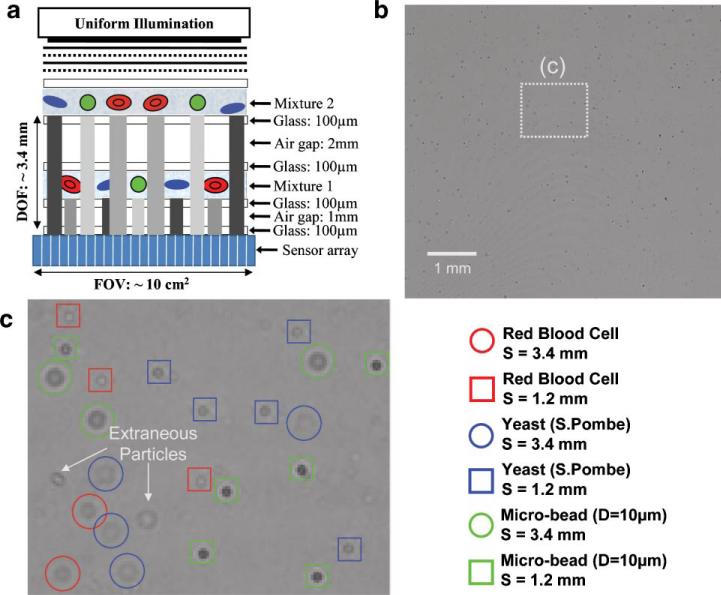
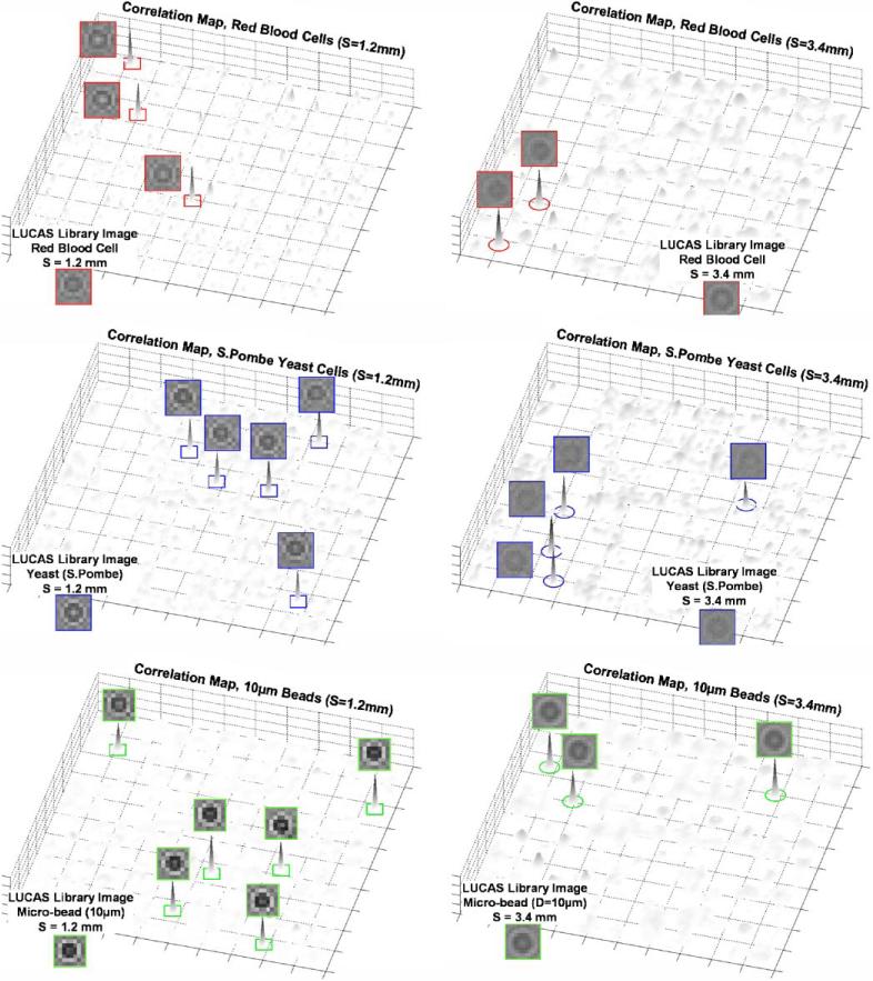
To further explore the feasibility of multi-layer LUCAS characterization, in Figure 8 we illustrate the results of a LUCAS experiment for a two-layered structure that extends over a DOF of ~3.4 μm. Each layer in this experiment contains a heterogeneous mixture of RBCs, yeast cells (S. Pombe) and 10 μm beads located at planes S = 1.2 mm and S = 3.4 mm (see Fig. 8). Figure 8b shows the raw LUCAS image corresponding to this two-layered structure, and Figure 8c shows a zoomed region of interest, where the automated characterization results of the LUCAS decision algorithm are illustrated. To point to the details of this decision making process, similar to Figure 5, we also show in Figure 9 the 2D correlation map of each micro-object type located at both of the object planes. Figure 9 clearly illustrates that using the LUCAS library image of the target cell/micro-object type, an automated correlation analysis of the LUCAS images (as discussed in the Materials and Methods Section) yields unique correlation peaks for each target object type. As illustrated in Figure 9, based on these correlation maps corresponding to each target micro-object type, unambiguous recognition of the diffraction signatures of cells/particles located at different DOF planes is feasible. Notice also that in Figure 9 the noise floor for the longer DOF (S = 3.4 mm) is higher for all the micro-objects when compared to the shorter DOF plane (S = 1.2mm). The main reason for this behavior is the reduced contrast and SNR in each LUCAS shadow due to increased effect of diffraction. However, the correlation peaks of the target objects with the LUCAS library image is still quite strong, yielding to the correct decision regardless of the increased noise floor at longer DOF values.
Figure 8.
The results of an automated LUCAS characterization of a heterogeneous mixture of RBCs, yeast cells and 10 μm beads imaged over a DOF of ~3.4 μm are illustrated. a: The same heterogeneous mixture is loaded on two different planes (S = 1.2 μm and S = 3.4 μm) and imaged using LUCAS. b: LUCAS raw image of this two layered mixture is shown. c: The results of the LUCAS decision algorithm are illustrated. The unique diffraction signature of each RBC, yeast cell and microbead located at two different layers (separated by >2 μm) is identified automatically. The details of the 2D correlation maps that are used for the decision making are illustrated in Figure 9 for each cell/micro-object type. [Color figure can be seen in the online version of this article, available at www.interscience.wiley.com.]
Figure 9.
The 2D correlation maps are illustrated for the LUCAS experiment shown in Figure 8. The left panel shows S = 1.2 mm plane whereas the right plane shows the S = 3.4 mm plane. For each plot, the LUCAS library image of the target micro-object is also shown at the bottom. Notice that the noise floor for the longer DOF (S = 3.4 μm) is higher for all the micro-objects; however, the correlation peaks of the target objects with the LUCAS library image is quite strong, yielding to the correct decision=regardless of the increased noise floor. [Color figure can be seen in the online version of this article, available at www.interscience.wiley.com.]
We should emphasize here that for a multi-layered sample of interest that is imaged using LUCAS, some of diffraction patterns of the particles/cells on different layers might statistically overlap with each other causing interference in their corresponding LUCAS pattern on the sensor array. This interference could result in a characterization error as the correlation of the interfering pattern with the LUCAS library images would now be degraded. This overlap problem could be especially severe for a high density of cells. However, as briefly discussed earlier, for a sensor array that has >10,000,000 pixels, a statistical error rate of <10% can be achieved for a uniformly distributed heterogeneous cell solution of ≤50,000 cells (total for all the layers of interest).
Discussion
In the large depth-of-field LUCAS imaging results illustrated above, different object planes were separated from each other by ≥100 μm, forming the multi-layered object such as in Figure 8. If this physical separation between different object planes were to be reduced to <50 μm, the under-sampled diffraction patterns corresponding to the same micro-particle type located at adjacent planes would be quite similar to each other, not only in 2D texture but also in signature strength and contrast. This can potentially cause errors in identifying the depth of the plane for a given micro-object type within the sample volume. One possible solution to this issue could be the use of a smaller pixel size sensor array which can improve the spatial sampling of minute differences in the diffraction patterns of adjacent planes. On the other hand, this approach will ultimately reduce the field of view of the LUCAS platform, as it will demand more pixels per diffraction signature of each micro-object/cell. A more complete solution for improving the localization accuracy in vertical (i.e., DOF) direction would be to utilize angled illumination; that is, by changing the angle of illumination of the LUCAS platform, the 2D pattern of different micro-objects at different plane heights will shift different amounts depending on the height of the object plane from the sensor array. For instance the 2D signatures of the micro-particles close to the sensor plane will shift within the LUCAS image much less than other micro-particles of the same kind that are located at higher depth of field values. This multi-angle illumination LUCAS platform may therefore provide an additional degree of freedom to existing parameters (such as texture, width and signature strength/contrast) to further improve the depth localization accuracy of the LUCAS algorithm.
The diffraction pattern of each cell type strictly depends on the illumination conditions such as the wavelength, spatial coherence and object plane height. However, under fixed illumination conditions, the 2D texture of the diffraction signature of a given cell type physically depends on three quantities: (i) the 3D morphology of the cell; (ii) the refractive indices of the cell and its surrounding medium; and (iii) the size of the cell. This directly implies that during apoptosis, since cells exhibit unique morphology changes (such as significant shrinkage), the LUCAS platform can potentially discriminate vital cells from apoptotic cells based on the variation of the classical diffraction pattern of the cell. However, we should emphasize that not all cell types would exhibit a detectable shadow signature difference for automated characterization. The same is also true for conventional lens based microscopy, that is, some cells look quite the same even under high optical magnification. In earlier sections we gave examples where the LUCAS shadow signature of different cell lines and other particles were uniquely different from each other and could be automatically characterized using the LUCAS decision algorithm. However, there are still various other cell types (e.g., CD4 vs. CD8 cells among others) which share quite similar morphology and refractive index values, as a result of which their LUCAS signatures would yield comparable shadow patterns making their automated characterization rather difficult. To address this specificity issue of the LUCAS platform for such similar looking cell types one can follow the following methodologies: (1) dielectric microbead labeling, (2) fluorescent labeling; and (3) surface chemistry.
Dielectric Microbead Labeling in LUCAS
Figure 2 clearly indicates that a polystyrene microbead (regardless of its diameter) exhibits an opposite contrast when compared to other cell lines. This contrast reversal provides the basis for dielectric microbead based specific labeling of a target cell type for significantly varying its LUCAS signature. Therefore, a target cell type can be specifically imaged within a heterogeneous cell solution by using polystyrene microbeads that are coated with an antibody corresponding to the CD marker of the target cell type. Because target cells that are labeled with the microbead will now exhibit a uniquely different shadow texture when compared to other cell types within the same solution, the specificity of the LUCAS platform will be significantly improved.
Fluorescent Labeling in LUCAS
Another approach that one can utilize to bring molecular specificity to LUCAS is to use fluorescent labeling. For this purpose, we can use fluorescent dyes that are conjugated with antibodies of a specific glycoprotein on the cell membrane. This way, within a solution containing many different types of cells, we can specifically label a target cell type. To selectively read out the fluorescence signal coming from dye molecules, we can use thin film filters deposited onto the active region of the sensor array or at the bottom of the used microfluidic channel, which selectively transmit only the fluorescence signal. Thus, using such thin-film filters, we can record LUCAS images of only the labeled cells. After the acquisition of these fluorescent LUCAS images, we can digitally compute the specific count of the labeled cells by utilizing the LUCAS decision algorithm, which will also be trained for similar lensfree fluorescence images using homogenous solutions of the same labeled cell type. This approach is quite different than the previously reported fluorescence based cell counting technologies since it offers a lensless on-chip platform, and is therefore much simpler and easier to miniaturize. Further, ultra-wide FOV of LUCAS allows analyzing much larger volume (~4 mL) in a single test, significantly increasing the throughput of characterization.
Use of Label-Free Surface Chemistry in LUCAS
A third alternative approach that can be used to bring molecular specificity to LUCAS is the use of surface chemistry based microfluidic devices. Such label-free microfluidic technologies have been shown to have cell capture efficiency and specificity of >90% and >85%, respectively (Cheng et al., 2005, 2007). The specificity of this approach is due to antibody coating of the inner surface of the microfluidic channels. To avoid nonspecific capture of other cell types that also express the target CD proteins, a controlled flow rate through the microfluidic channels can also be used. By controlling the flow rate, one can create an optimum shear stress within the channels, which can break the bonds of non-specifically captured cells before the target cells’ bonds are broken. This microfluidic technology can be integrated with LUCAS platform in a compact, self-contained unit to measure the count of the captured cells within the microfluidic chips without the use of any labeling agents.
For the same cell type that are obtained from different sources (such as RBCs obtained from two different healthy donors), the overall LUCAS signatures showed very similar properties as the above mentioned physical parameters would on average be the same regardless of the source of the cells of the same kind. As far as the passage number of the cells is concerned, since for high passage numbers the morphology of the cell can potentially start to deform, its statistical LUCAS signature may deviate from the low passage number of the same cell kind. However, such effects should only be visible for “unhealthy cells” corresponding to a large passage number, and can potentially be minimized by independently monitoring the state of the cell population through other means such as the protein expression level.
The experimental results presented in this manuscript were acquired using floating/suspended cells, that is, the imaged cells were not attached to a substrate. Note also that adherent growing cell types such as fibroblasts that are imaged using LUCAS were all detached from the substrate during imaging. However, for imaging/monitoring of surface adhered cells, the effect of the surface properties of the substrate on the shadow image should also be investigated. For this end, a new training set for each adherent cell type for a given substrate needs to be acquired to create a statistical image library for each cell-substrate combination. This statistical LUCAS image library can then be used to fine tune the decision algorithm for identification of each adherent cell type for a given substrate. We should note that a more detailed analysis of a larger scale LUCAS signature library corresponding to various other cell types (both adherent and non-adherent), together with a discussion on the effect of the optical properties of the LUCAS substrate and illumination wavelength on the image signal-to-noise ratio and the LUCAS shadow signature is currently under investigation and will be provided in a further study.
Conclusions
In summary, we described a lensfree high-throughput on-chip imaging platform that can potentially characterize ~50,000 cells within a heterogeneous cell mixture over depth-of-field of ~4 mm and a field-of-view of ~10 cm2. We illustrated that the unique diffraction signatures of different cell types and other micro-particles may enable unambiguous automated characterization of a heterogeneous solution of 4 ~mL volume. For high-throughput cell counting and characterization applications, where the main aim is to rapidly count and identify cells over a large volume or to dynamically monitor the location of thousands of cells, LUCAS may provide numerous advantages over conventional microscopes, such as a significantly increased sample volume, reduced complexity, and ease of miniaturization. Furthermore, LUCAS can also be integrated with micro-fluidic channels providing massively parallel on-chip monitoring, counting and characterization of cells without using expensive and bulky optical components. This technology may have a significant impact especially for the developing world, where the resources are scarce, by enabling a point-of-care cell counting device as small as a regular cell-phone that uses for example, surface-chemistry based micro-fluidic devices or fluorescent markers to test the blood samples of patients with minimum amount of reagent use.
References
- Burger D, Gershman R. Acoustooptic laser scanning cytometer. Cytometry. 1988;9:101–110. doi: 10.1002/cyto.990090202. [DOI] [PubMed] [Google Scholar]
- Cheng X, Irimia D, Dixon M, Ziperstein JC, Demirce U, Zamir L, Tompkins RG, Toner M, Rodriguez WR. A microchip approach for practical label-free CD4+ T-Cell counting of HIV-Infected subjects in resource- poor settings. J. Acquir Immune Defic Syndr. 2005;45:257–261. doi: 10.1097/QAI.0b013e3180500303. [DOI] [PubMed] [Google Scholar]
- Cheng X, Irimia D, Dixon M, Ziperstein JC, Demirce U, Zamir L, Tompkins RG, Rodriguez W, Toner M. A microfluidic device for practical label-free CD4+ T cell counting of HIV-infected subjects. Lab Chip. 2007;7:170–178. doi: 10.1039/b612966h. [DOI] [PMC free article] [PubMed] [Google Scholar]
- Chin CD, Linder V, Sia SK. Lab-on-a-chip devices for global health: Past studies and future opportunities. Lab Chip. 2006;7:41–57. doi: 10.1039/b611455e. [DOI] [PubMed] [Google Scholar]
- Darzynkiewicz Z, Elzbieta B, Li X, Gorczyca W, Myron Melamed MR. Laser-scanning cytometry: A new instrumentation with many applications. Exp Cell Res. 1999;249:1–12. doi: 10.1006/excr.1999.4477. [DOI] [PubMed] [Google Scholar]
- Hulett HR, Bonner WA, Sweet RG, Herzenberg LA. Development and application of a rapid cell sorter. Clin Chem. 1973;19:813–816. [PubMed] [Google Scholar]
- Joo S, Chung TD, Kim HC. A rapid field-free electroosmotic micro-pump incorporating charged microchannel surfaces. Sens Actuators B Chem. 2007;132:1161–1168. [Google Scholar]
- Kamei T, Paegel BM, Scherer JR, Skelley AM, Street RA, Mathies RA. Integrated hydrogenated amorphous Si photodiode detector for micro-fluidic bioanalytical devices. Anal Chem. 2003;75:5300–5305. doi: 10.1021/ac0301550. [DOI] [PubMed] [Google Scholar]
- Kamentsky LA, Burger DE, Gershman RJ, Kamentsky LD, Luther E. Slide-based laser scanning cytometry. Acta Cytol. 1997;41:123–143. doi: 10.1159/000332315. [DOI] [PubMed] [Google Scholar]
- Lancaster C, Kokoris A, Nabavi M, Clemmens J, Maloney P, Capadanno J, Gerdes J, Battrell CF. Rare cancer cell analyzer for whole blood applications: Microcytometer cell counting and sorting subcircuits. Methods. 2005;37:120–127. doi: 10.1016/j.ymeth.2005.07.003. [DOI] [PubMed] [Google Scholar]
- Lee JS. Speckle analysis and smoothing of synthetic aperture radar images. Comput Graph Image Process. 1981;17:24–32. [Google Scholar]
- Lee JW. Global health improvement and WHO: Shaping the future. Lancet. 2003;362:2083–2088. doi: 10.1016/S0140-6736(03)15107-0. [DOI] [PMC free article] [PubMed] [Google Scholar]
- Lien V, Zhao K, Berdichevsky Y, Lo YH. High-sensitivity cytometric detection using fluidic-photonic integrated circuits with array waveguides. IEEE J Sel Top Quantum Electron. 2005;11:827–834. [Google Scholar]
- Macnab RM, Koshland DE. The gradient-sensing mechanism in bacterial chemotaxis. Proc Natl Acad Sci. 1972;69:2509–2512. doi: 10.1073/pnas.69.9.2509. [DOI] [PMC free article] [PubMed] [Google Scholar]
- Niehren S, Kinzelbach W, Seeger S, Wolfrum J. An all-solid-state flow cytometer for counting fluorescent microspheres. Anal Chem. 1995;67:2666–2671. [Google Scholar]
- Novak L, Neuzil P, Pipper J, Zhang Y, Lee SH. An integrated fluorescence detection system for lab-on-a-chip applications. Lab Chip. 2007;6:27–29. doi: 10.1039/b611745g. [DOI] [PubMed] [Google Scholar]
- Ozcan A, Bilenca A, Bouma BE, Tearney GJ. Mirror tunnel microscope. Appl Phys Lett. 2006;89:131124. [Google Scholar]
- Ozcan A, Demirci U. Ultra wide-field lens-free monitoring of cells on-chip. Lab Chip. 2007;8:98–106. doi: 10.1039/b713695a. [DOI] [PubMed] [Google Scholar]
- Steinberg DM, Ali SZ. Application of virtual microscopy in clinical cytopathology. Diagn Cytopathol. 2001;25:389–396. doi: 10.1002/dc.10021. [DOI] [PubMed] [Google Scholar]
- Weinstein R, Descour M, Liang C, Barker G, Scott K, Richter L, Krupinski E, Bhattacharyya A, Davis J, Graham A. An array microscope for ultra-rapid virtual slide processing and telepathology. Design, fabrication, and validation study. Hum Pathol. 2004;35:1303–1314. doi: 10.1016/j.humpath.2004.09.002. [DOI] [PubMed] [Google Scholar]
- Wolff A, Nielsen P, Larsen UD, Friis P, Goranovic G, Poulsen CR, Kutter JP, Telleman P. Integrating advanced functionality in a microfabricated high-throughput fluorescent-activated cell sorter. Lab Chip. 2003;3:22–27. doi: 10.1039/b209333b. [DOI] [PubMed] [Google Scholar]


