Summary
The effect of phosphotungstic acid (PTA) and iodine solution (IKI) staining was investigated as a method of enhancing contrast in the X-ray computed tomography of porcine anterior cruciate ligaments (ACL) and patellar tendons (PT). We show that PTA enhanced surface contrast, but was ineffective at penetrating samples, whereas IKI penetrated more effectively and enhanced contrast after 70 hours of staining. Contrast enhancement was compared when using laboratory and synchrotron based X-ray sources. Using the laboratory source, PT fascicles were tracked and their alignment was measured. Individual ACL fascicles could not be identified, but identifiable features were evident that were tracked. Higher resolution scans of fascicle bundles from the PT and ACL were obtained using synchrotron imaging techniques. These scans exhibited greater contrast between the fascicles and matrix in the PT sample, facilitating the identification of the fascicle edges; however, it was still not possible to detect individual fascicles in the ACL.
Keywords: anterior cruciate ligament, contrast enhancement, fascicle, patellar tendon, staining, X-ray tomography
Introduction
The anterior cruciate ligament (ACL) is the most frequently injured knee ligament, and is one of the structures most commonly injured in sport1. Due to the fact that it does not heal naturally, the standard treatment for a ruptured ACL is surgical reconstruction2; to which there are several approaches, the most common being patellar tendon (PT) and hamstring tendon autograft. There is currently no consensus with respect to the choice between these two grafts2, however, the PT has traditionally been the most commonly used3. In order to understand the differences in the mechanical properties of these ligaments, it is important to determine the geometrical arrangement of their fascicles. Previous attempts to do this have been based either on the slicing and investigation of ligament samples via microscope4,5 or on the identifying and tracking of surface fascicles6. Unfortunately, slicing a ligament risks altering its geometry as a result of residual stress and tracking surface fascicles does not give any information on the orientation of interior fascicles.
Recent advances in X-ray computed tomography (XCT), instrument resolution and image processing have enabled the visualisation of soft tissues in embryos and invertibrates7,8, and of fascicles in foetal porcine extensor digitorum longus muscles9 and the human extensor carpi ulnaris tendon10. The scope of this article is to give a brief overview of the potential of phosphotungstic acid (PTA) and iodine solution (IKI) staining for increasing contrast in the imaging of porcine ACL and PT. We show that IKI appears to penetrate the ACL and PT samples more effectively, enabling the three-dimensional visualisation of the interior structure of these ligaments. In the long term, the technique discussed here could be optimised in order to determine the collagen volume fraction and fascicle alignment in any tendon or ligament sample, which would provide crucial information for any attempt to predict mechanical behaviour as a function of microstructure.
Materials and methods
Two ACL and two PT samples were dissected from two pig legs sourced locally with their bone attachments still in place. It is known that the the fascicles in the ACL are twisted around each other as the knee flexes, and that the level of twist is dependent upon the flexion angle of the knee11. The twist is at a minimum when the knee is in full extension, and at a maximum when the knee is in maximal flexion11. The interest here was to determine ACL fascicle alignment when the knee is in an intermediary position, therefore, our ACL samples were dissected with the knee in approximately 90° of flexion, and the orientation of the ACL was maintained as closely as possible throughout the preparation procedure. The bone attachments at both ends of each sample were glued to small aluminium discs using Loctite 435 and Perspex rods were glued in place to keep the ligaments taut and as close as possible to their in situ length. All samples were fixed in 10% formalin solution for 48 hours in this position, then one sample of each type was stained for 15 hours with PTA solution (0.3% phosphotungstic acid in 70% ethanol) before being scanned, then stained and scanned further in increments of five hours up to a total of 50 hours. The samples were then stained for a further 100 hours before they were scanned for a final time. The remaining samples were stained in IKI solution [1% iodine metal (I2) + 2% potassium iodide (KI) in water], diluted to 10% in water just before use, for 70 hours before being scanned. Finally, the IKI stained samples were stained for a further 50 hours before a small group of fascicles was dissected out from each sample and scanned using the I13 beam-line of the synchrotron at the Diamond Light Source.
The PTA and IKI stained samples were all transferred to Perspex containers filled with 70% ethanol for each scan, with the iodine stained samples being rinsed with water to remove excess stain and prevent surface saturation before being transferred. They were then imaged using a Nikon Metris 225/320 kV system housed in a customised bay with a 2K x 2K Perkin Elmer 1621-16-bit amorphous silicon flat-panel detector with 200 micron pixel pitch at the Henry Moseley X-ray Imaging Facility at The University of Manchester. The source to specimen and source to detector distances were optimised for each set of samples. The source to specimen distance was 86 mm for the PTA stained samples and 80 mm for the IKI stained samples. The source to detector distance was 1393 mm for all samples. The samples were placed on the Nikon Metris 225/320 kV CT system rotation stage and were scanned with a tungsten source, with an accelerating voltage of 60 kV, a current of 280 μA and a gain of 30 dB. A total of 2001 projections were taken over 360° with an exposure time of 708 ms/projection, giving a total acquisition time of just under 24 minutes. The resolutions obtained were 12.4 μm/voxel for the PTA stained samples and 11.4 μm/voxel for the IKI stained samples. The IKI stained fascicle bundles were scanned in air using the I13 synchrotron beamline at the Diamond Light Source with a monochromatic beam with an energy level of 15 keV. A total of 1800 projections were taken over 180° with an exposure time of one second, giving a total acquisition time of 30 minutes. The camera used to collect the synchrotron data was a PCO 4000s using a 4x objective lens, giving an effective pixel size of 0.92 μm.
After image acquisition, data sets were reconstructed using the Nikon Metris CT-Pro reconstruction software (Metris XT 1.6, version 2.1.3509.24 387, 10 August 2009). Radiographs and reconstructed imaged slices were viewed with the GNU Image Manipulation Program 2.6.1112 and ImageJ1. 4313 and 3D reconstructed volumes were segmented using Avizo standard 7.0 (Visualization Sciences Group, Bordeaux (VSG), France). Calculations of the organisation of the sample fascicles were made using MATLAB 2010a (Math-Works, Inc., Natick, Massachusetts, USA).
The research in this article was conducted according to the ethical guidelines detailed in Padulo et al.14.
Results
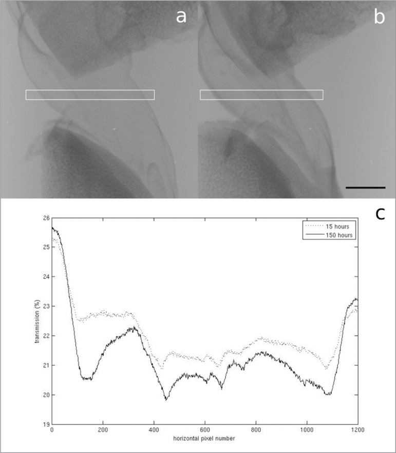
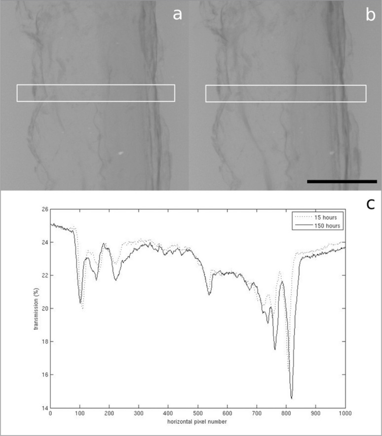
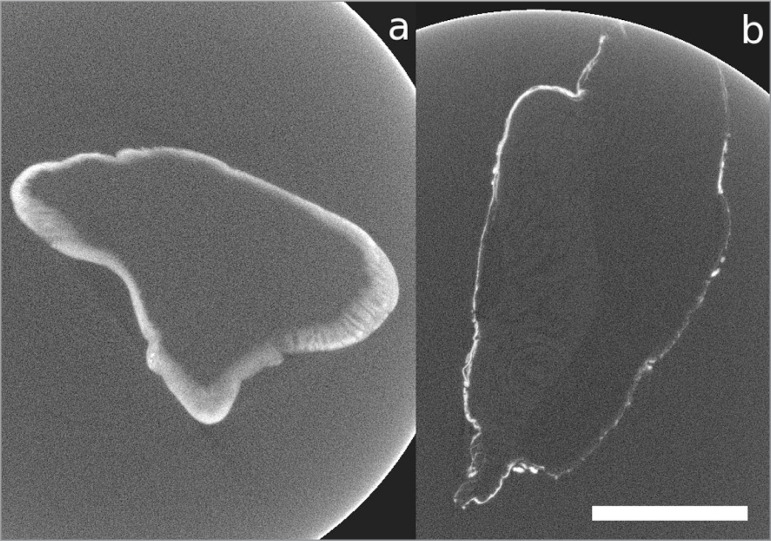
In the samples stained with PTA, very little difference in contrast was observed as a result of a five hour increment in staining time, but there did appear to be a slight increase in contrast after 150 hours compared to 15 hours (Figs. 1, 2). Unfortunately, however, there was very little penetration of the stain into either ligament sample (Fig. 3). In Figure 3a, no features can be identified beyond the very thin outer region (estimated to be between 200 μm and 1 mm thick) where the stain has penetrated, whereas in Figure 3b, the collagen of the PT can be identified, but the stain, which appears to have only penetrated to an estimated depth of between 50 μm and 150 μm, does not appear to be enhancing its contrast.
Figure 1 A–C.
A. Radiograph of the ACL stained with PTA for 15 hours. B. Radiograph of the ACL stained with PTA for 150 hours. Scale bar = 5 mm. The white boxes show the area the transmission profiles are plotted over. C. Plot of the transmission of X-rays through the centre of the ACL radiographs. The lower average transmission in the sample stained for 150 hours indicates a greater attenuation of X-rays.
Figure 2 A–C.
A. Radiograph of the PT stained with PTA for 15 hours. B. Radiograph of the PT stained with PTA for 150 hours. Scale bar = 5 mm. The white boxes show the area the transmission profiles are plotted over. C. Plot of the transmission of X-rays through the centre of the PT radiographs. The lower average transmission in the sample stained for 150 hours indicates a greater attenuation of X-rays.
Figure 3 A–B.
A. Imaged cross-sectional slice of the ACL; B. imaged cross-sectional slice of the PT, after 150 hours of PTA staining. Scale bar = 5 mm.
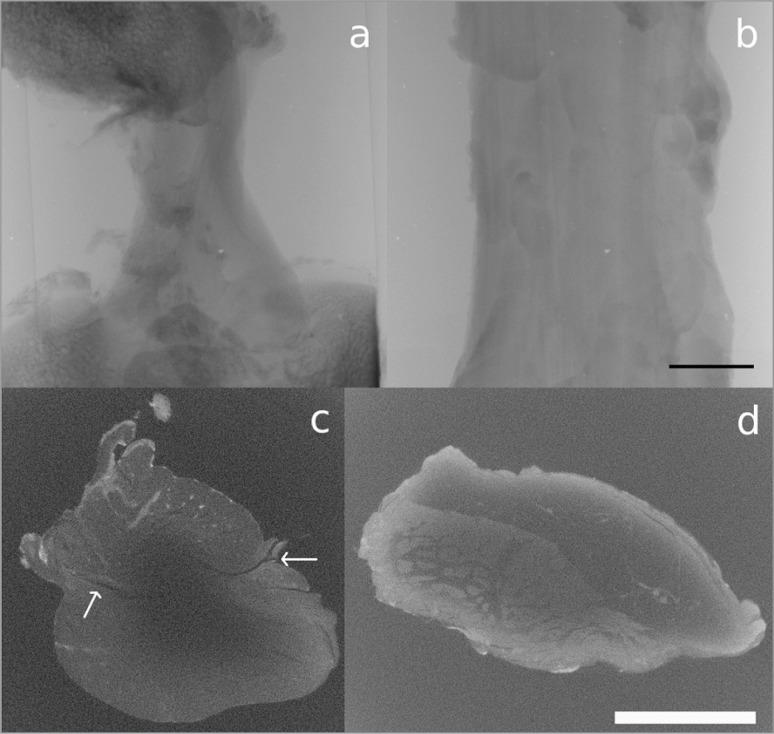
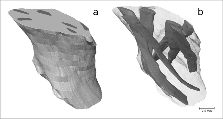
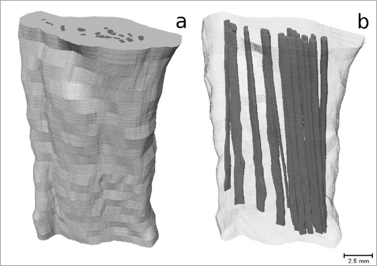
The use of IKI staining appears to be much more promising. After 70 hours of staining, although the surface contrast does not appear to be as strong as in the PTA stained samples, the stain had penetrated much further than it had in the PTA case (Fig. 4). Individual fascicles can be identified in the PT, which can be tracked through each slice to determine their orientation relative to the longitudinal axis of the tendon. In the ACL sample, although individual fascicles cannot be identified, there are identifiable features which can be tracked. The features that were tracked were regions of high grey-level value, representing areas that had attenuated more X-rays than the surrounding area, therefore potentially indicating a different tissue type. Assuming that the ACL fascicles have the same alignment as these features, the angle they make with the longitudinal axis of the ligament can also be measured. We also observe a dark band on either side of the ACL cross-section (indicated by arrows in Fig. 4c). It was not possible to track this band through the cross-section due to the lack of contrast in the centre region, but it may be that this band indicates the divide between the antero-medial and postero-lateral bundles of the ACL. In Figure 5 we show a 3D reconstruction of the IKI stained ACL with the identifiable features tracked through each imaged slice to show the orientation of the ligament’s fascicles. In Figure 6 we show a 3D reconstruction of the IKI stained PT, with the fascicles tracked through each imaged slice.
Figure 4 A–D.
A. Radiograph of the ACL, B. radiograph of the PT, C. imaged cross-sectional slice of the ACL, D. imaged cross-sectional slice of the PT, after 70 hours of IKI staining. Scale bars = 5 mm. The arrows in c. point to a dark band that may indicate the divide between the antero-medial and postero-lateral bundles of the ACL.
Figure 5 A–B.
3D reconstruction of the IKI stained ACL; A. outer surface, B. interior with features tracked through each slice to show the orientation of the ligament’s fascicles.
Figure 6 A–B.
3D reconstruction of the IKI stained PT; A. outer surface, B. interior with fascicles tracked through each slice.
The features were tracked along a 1.31 cm section of the ACL and a 2.28 cm section of the PT, and were manually segmented through the volume using Avizo 7.0. The 3D image generated showed that the features in the ACL are helically arranged, whereas, the PT fascicles appear to be straight. To demonstrate the change in the position of the fascicles relative to the centre of the sample, the centroid (geometric centre) of each sample and of each of the features within it was calculated for each slice of the reconstructed volume. Tracking these centroids through the length of the reconstructed volume showed the orientation of each sample’s features.
The average angle the features in the ACL made with its axis was 24° (standard deviation 10°, range 14°–45°, 6 individual features tracked), whereas the average angle the fascicles in the PT made with its axis was 4°, (standard deviation 2°, range 1°–9°, 19 individual fascicles tracked).
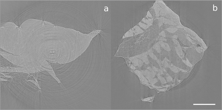
Imaged cross-sections of the fascicles dissected from the ACL and PT, which were obtained via synchrotron imaging techniques, are shown in Figure 7. The scan of the PT fascicle bundle exhibits greater contrast between the fascicles and matrix than the scans obtained using an X-ray laboratory source. We can quantify this difference in contrast in terms of the contrast enhancement index (CEI), defined by CEI = (G(F)-G(M))/(G(F)+G(M)), where G(F) is the average grey-level of a fascicle in a cross-sectional slice, and G(M) is the average grey-level in the tendon’s matrix. The CEI was calculated to be 0.307 for the synchrotron images and 0.096 for the laboratory source images. This increased contrast is likely to be due to the use of monochromatic light at a lower energy, both improving attenuation contrast and adding in some phase contrast. The increased dynamic sensitivity of the detector system and the fact that the samples were scanned in air rather than in ethanol were also beneficial. Unfortunately, no further details are apparent in the ACL sample. We note that scanning biological tissues in air can lead to them drying out, which could be the cause of the movement arte-facts that are apparent in Figure 7. We also note that Figure 7 has a more consistent grey-level than Figure 4. This could either be because the stain had fully and consistently perfused into the samples after 130 hours, or because the use of a monochromatic beam eliminated the possibility of beam hardening effects that could have been present in the scans performed with a laboratory source. It would be of interest to perform further scans on heavily stained samples to determine whether the inconsistent grey-levels in Figure 4 are due to insufficient stain perfusion or due to beam hardening.
Figure 7 A–B.
Imaged cross-sectional slice of a bundle of fascicles dissected from A. the ACL and B. the PT, after 130 hours of staining with IKI, obtained using the I13 beamline of the synchrotron at the Diamond Light Source. Scale bar = 1 mm.
Discussion
Our findings confirm that XCT can be used to non-destructively image the features within porcine ACL and PT. PTA appears to be ineffective as a contrast agent over the time-scales and at the concentration used here, however, IKI staining appears to be much more promising. After 70 hours of IKI staining, it was possible to visualise individual fascicles within the PT, and some identifiable features could be made out in the ACL. The diameter of the ACL sample ranged between 8 mm and 10 mm, and that of the PT sample ranged between 7 mm and 14 mm; larger samples may require longer staining times, which may be an issue in the scanning of human samples, for example. We have observed that the fascicles in the PT are relatively strongly aligned with its axis, whereas, assuming the ACL fascicles follow its identifiable features, it appears they are helically aligned and make a much larger angle with the ligament’s axis. We note, however, that the alignment of the ACL fascicles is dependent on the position of the knee. The position of the ACL when being scanned in this study was equivalent to its in situ position if the knee had been in 90° of flexion.
We note that individual fascicles can be identified in the PT sample, but cannot in the ACL sample. By comparing our results with the histological data of Yahia and Drouin4,5, we can offer a possible explanation for this difference. Yahia and Drouin4,5 observed that the paratenon and epitenon surrounding the fascicles is considerably thicker in the PT than in the ACL. If the thickness of this connective tissue in our ACL sample was smaller than the resolution of the images obtained, this would explain why it was not possible to distinguish between individual fascicles in Figure 4c. Yahia and Drouin4,5 also noted a heterogeneity in the collagen distribution of the PT, with the anterior region consisting of dense and thick collagenous fascicles, and the posterior region being composed of small, single fascicles embedded in loose areloar tissue. An inspection of Figure 4d shows that this also appears to be the case in our PT sample, with the anterior region of the PT being closer to the centre of the image, joining with the subcutaneous fat that can be observed towards the top and right of the figure.
The main strength of this study is that the methodology used does not require ligament and tendon samples to be sliced, therefore, the microstructures of the ACL and PT were imaged without damaging their ultrastructure and potentially affecting the alignment of their fascicles. Another strength is that the techniques described here could be easily applied to any other ligament or tendon sample of a similar size. A limitation of the study, however, is that the stain had not perfused consistently into the centres of the ACL and PT samples within the time-frames and at the concentration levels used here. Additionally, the size of the samples limited the resolution it was possible to obtain whilst fitting the whole sample into the scanner’s field of view. It is possible that a greater level of detail could be observed in smaller samples than those imaged in this study.
Further work could be undertaken to determine the optimal staining time and concentration when using IKI staining to enhance contrast in the XCT of the ACL and PT. An additional study could also be carried out into the use of phase contrast, as utilised by Kalson et al.10, to obtain increased definition between a sample’s fascicles and matrix material. Finally, it would be of interest to image ACL samples in different levels of flexion (for example, full extension and full flexion) to determine how ACL fascicle alignment varies with knee flexion angle.
In summary, we have shown that IKI can be used to enhance contrast in XCT of porcine ACL and PT samples. With some additional work, it should be possible to optimise this technique in order to obtain the same level of contrast enhancement in the centre of samples as on the edges. In the long term, this will allow us to quantify the collagen volume fraction and fascicle alignment in any ligament or tendon sample via the three-dimensional images produced using XCT, which we are not currently able to do via two-dimensional histological analysis.
Acknowledgments
We are grateful to the Engineering and Physical Research Council for funding this work and the MXIF at the Research Complex at Harwell (EP/102248X/1), and the Diamond-Manchester Collaboration for providing time on the Diamond-Manchester Beam-branch. We also thank K. Kadler, A. Hazel, W. Parnell and S. Anand for the advice they have provided, M. O’Brien for aiding in the fixation and staining of the samples and K. Madi for assisting in the scanning of our samples at the Diamond Light Source. Finally, we thank Stryker for providing the dissection saw used to obtain the ligament samples.
References
- 1.Ryder SH, Johnson RJ, Beynnon BD. Prevention of ACL injuries. J Sport Rehabil. 1997;6:80–96. [Google Scholar]
- 2.Mohtadi NGH, Chan DS, Dainty KN, Whelan DB. Patellar tendon versus hamstring tendon autograft for anterior cruciate ligament rupture in adults (Review) The Cochrane Library. 2011;9 doi: 10.1002/14651858.CD005960.pub2. [DOI] [PMC free article] [PubMed] [Google Scholar]
- 3.Chandrashekar N, Slauterbeck J, Hashemi J. Effects of cyclic loading on the tensile properties of human patellar tendon. The Knee. 2012;19:65–68. doi: 10.1016/j.knee.2010.11.014. [DOI] [PubMed] [Google Scholar]
- 4.Yahia LH, Drouin G. Collagen structure in human anterior cruciate ligament and patellar tendon. J Mater Sci. 1988;23:3750–3755. [Google Scholar]
- 5.Yahia LH, Drouin G. Microscopial investigation of canine anterior cruciate ligament and patellar tendon: Collagen fascicle morphology and architecture. J Orthop Res. 1989;7:243–251. doi: 10.1002/jor.1100070212. [DOI] [PubMed] [Google Scholar]
- 6.Zhang X, Jiang G, Wu C, Woo SLY. A subject-specific finite element model of the anterior cruciate ligamentW:. In Proceedings of the 30th Annual International IEEE Engineering in Medicine and Biology Society Conference; Vancouver, British Columbia, Canada. 2008; pp. 891–894. [DOI] [PubMed] [Google Scholar]
- 7.Metscher BD. MicroCT for comparative morphology: simple staining methods allow high-contrast 3D imaging of diverse non-mineralized animal tissues. BMC Physiology. 2009;9:11. doi: 10.1186/1472-6793-9-11. [DOI] [PMC free article] [PubMed] [Google Scholar]
- 8.Metscher BD. MicroCT for developmental biology: a versatile tool for high-contrast 3D imaging at histological resolutions. Dev Dyn. 2009;238:632–640. doi: 10.1002/dvdy.21857. [DOI] [PubMed] [Google Scholar]
- 9.Jeffery NS, Stephenson RS, Gallagher JA, Jarvis JC, Cox PG. Micro-computed tomography with iodine staining resolves the arrangement of muscle fibres. J Biomech. 2011;22:189–192. doi: 10.1016/j.jbiomech.2010.08.027. [DOI] [PubMed] [Google Scholar]
- 10.Kalson NS, Malone PSC, Bradley RS, Withers PJ, Lees VC. Fibre bundles in the human extensor carpi ulnaris tendon are arranged in a spiral. J Hand Surg (European Volume) 2012;30:550–554. doi: 10.1177/1753193411433228. [DOI] [PubMed] [Google Scholar]
- 11.Amis A. The functions of the anterior cruciate ligament in anterior drawer, rotational laxity and the pivot shift. Knee Surg Sports Traumatol Arthrosc. 2012;20:613–620. doi: 10.1007/s00167-011-1864-7. [DOI] [PubMed] [Google Scholar]
- 12. http://www.gimp.org.
- 13. http://rsbweb.nih.gov/ij/
- 14.Padulo J, Oliva F, Frizziero A, Maffulli N. Muscles, Ligaments and Tendons Journal. Basic principles and recommendations in clinical and field science research. MLTJ. 2013;4:250–252. [PMC free article] [PubMed] [Google Scholar]


