Abstract
Additive manufacturing (3D printing) technology offers a great opportunity towards development of patient-specific vascular anatomic models, for medical device testing and physiological condition evaluation. However, the development process is not yet well established and there are various limitations depending on the printing materials, the technology and the printer resolution. Patient-specific neuro-vascular anatomy was acquired from computed tomography angiography and rotational digital subtraction angiography (DSA). The volumes were imported into a Vitrea 3D workstation (Vital Images Inc.) and the vascular lumen of various vessels and pathologies were segmented using a “marching cubes” algorithm. The results were exported as Stereo Lithographic (STL) files and were further processed by smoothing, trimming, and wall extrusion (to add a custom wall to the model). The models were printed using a Polyjet printer, Eden 260V (Objet-Stratasys). To verify the phantom geometry accuracy, the phantom was reimaged using rotational DSA, and the new data was compared with the initial patient data. The most challenging part of the phantom manufacturing was removal of support material. This aspect could be a serious hurdle in building very tortuous phantoms or small vessels. The accuracy of the printed models was very good: distance analysis showed average differences of 120 μm between the patient and the phantom reconstructed volume dimensions. Most errors were due to residual support material left in the lumen of the phantom. Despite the post-printing challenges experienced during the support cleaning, this technology could be a tremendous benefit to medical research such as in device development and testing.
Keywords: Vascular phantoms, 3D printing, additive manufacturing, patient specific phantoms, CT, Cone-Beam CT
1. Introduction
The purpose of this paper is to investigate the challenges and limitations of manufacturing patient-specific vascular phantoms using additive manufacturing or 3D printing. Our focus on vascular phantoms is prompted by the need for safer and more accurate catheter-based cardiovascular interventions and more effective diagnostic methods. Cardiovascular disease, including stroke, is the leading cause of death and cost 15% of total US health expenditures in 2009, more than any major diagnostic group.[1] Catheter endovascular procedures, while in their infancy, are associated with lower mortality due to reduced invasiveness. However, despite shorter surgery time and fewer hospitalization days, the costs of such procedures are not as low as expected.[2, 3] This paradox is largely related to the significant investment in research and development that is necessary for the refinement of such endovascular devices.[4]
Three dimensional printing offers a unique opportunity to build accurate patent-specific vascular phantoms which can be used for device testing, resident physician training, physiological simulations, physical measurements, as well as imaging system and software testing. Unlike computational studies, these phantoms could help in the design of experiments where diseases and physiologies are reproduced with high reliability and accuracy. Many of the iterative design steps involved in the development of endovascular devices could be performed at this stage, limiting the number of failures during in-vivo studies. In addition, by testing such technologies in uncommon patient geometries, device failures or limitations could be revealed before the clinical trials. Research and development engineers will be able to anticipate the problems early and adjust their design and strategy on the process, avoiding late damaging and expensive experiences.
Vascular diagnosis and endovascular treatment planning have evolved tremendously due to imaging tools such as 3D and 4D volumetric rendering, multi-planar reformation, fly-through graphics, curved multi-planar reformation, etc.[5] Facile access to such accurate patient specific vascular visualization tools and data sets, triggered an avalanche of computer simulation research studies such as computational fluid dynamics and virtual device placement.[6, 7] The clinical utility of such studies could be improved greatly if they could be validated using patient specific phantoms.[8]
When creating patient specific phantoms, one of the challenges that prevent wide use of this technology is development of computer models which can be used to manufacture these phantoms. 3D volumes with voxel sizes less than 0.5 mm are routinely available due to the great advancements that medical imaging has undergone in the last decade in terms of accuracy, speed and range of tools available for users. Modalities such as MDCT, MRI and C-arm CBCT offer routinely high-resolution large-volume patient data, which in return creates accurate 3D computer rendering in a short time interval.[9] Converting patent-specific geometries from CT or MRI scans in phantoms, which could be used routinely, is not a routine task. Commercial software such Vital Imaging offers capability to directly export STL files but these files are not optimal to create practical patient-specific phantoms. Currently, the process of creating a patient phantom ready for experimental testing, requires several post-processing steps which might involve usage of a few software platforms.
In this study we present the workflow for creating patient-specific vascular phantoms using a high resolution Polyjet printer. The PolyJet 3D printing is similar to inkjet document printing; the printer heads jet layers of liquid photopolymer onto a build tray and cure them with UV light. The layers build up one at a time to create a 3D model or prototype. This technology allows usage of multiple materials and has the highest resolution for a commercial 3D printer. As many other manufacturing processes, this approach has its advantages, challenges and limitations, especially when dealing with patient-specific vascular phantoms. Such phantoms consist of very complex fine structures and they pose significant challenges in manufacturing using 3D printing. The workflow challenges and limitations encountered during the process such as STL file design and post-print model processing are presented along with various advantages such as geometrical accuracy and mechanical evaluation related to neurovascular intervention simulations.
2. Materials and Methods
The work presented in this paper is composed of two parts: manufacturing and testing of patient-specific phantoms. In the phantom manufacturing part, we will present details of STL file creation for various phantoms and post-print phantom processing. The testing part will focus on geometry accuracy measurements, imaging validation using x-ray angiography and qualitative mechanical evaluation during an endovascular image-guided intervention. These steps were part of an iterative study until optimal models were obtained. In the following sub-sections, we present only the final workflow, leaving explanation of our choices for the discussion section.
2.1 Phantom Manufacturing
2.1.1 Stereo-Lithographic File Creation
File creation starts with acquisition of 3D patient data followed by 3D data segmentation and mesh manipulation. Complex phantoms involving many vascular structures pose various challenges revealed only in the final testing steps; hence they require a special treatment which will be presented separately. The main requirement for a usable STL file is that the mesh surface is continuous, and there are no open surfaces or self-intersections.
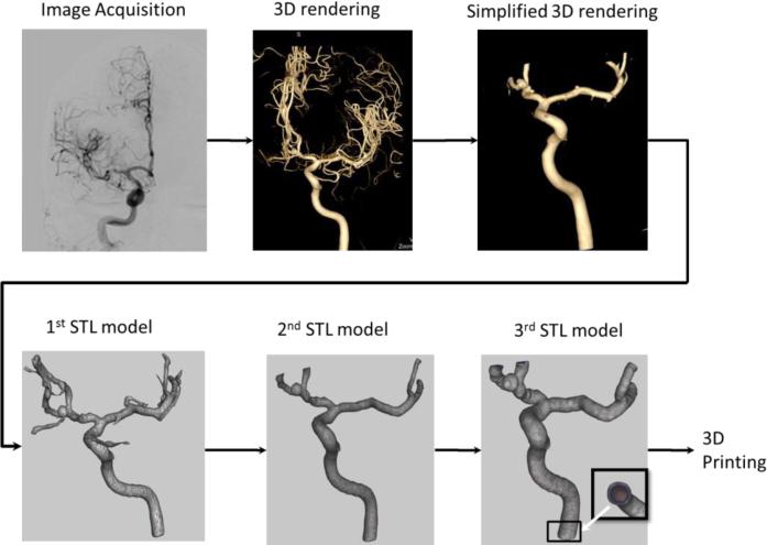
For a simple arterial geometry, Figure 1 outlines a typical flow diagram applied to create a Stereo Lithographic (STL) file which is used as a printer input. Patient data, Figure 1 (Image Acquisition Step), was acquired using rotational DSA and CTA with an angiographic C-arm system and a CT scanner Aquilion One (Toshiba Medical Systems Corp. Tustin CA). 3D data volumes with voxel sizes of 0.120 mm for the rotational DSA and 0.500 mm for the CTA, were loaded in a Vitrea 3D station (Vital Images, Inc. Minnetonka MN) for 3D rendering and processing, Figure 1 (3D Rendering Step). We manually selected a vessel of interest by placing a seed on a 3D volume or one of the CT slices. Starting with this seed, a dynamic vessel growing was performed. On the display we observed in real time the vessel growing and decided qualitatively how much of the peripheral vasculature should be included. The segmented geometry was further manipulated by trimming smaller branches to simplify the geometry (Figure 1 Simplified 3D Rendering Step). This simplification is needed due to practicability considerations in establishing a reliable outlet in an experimental flow loop.
Figure 1.
Flow diagram showing the steps performed in order to obtain a STL file for a simple phantom of a right internal carotid needed for the 3D printer.
The 3D Workstation allows direct export of the geometry as STL files, Figure 1(1st STL Model Step) using a “marching cubes” algorithm. However, these STL models are not ready to be printed. They require further mesh manipulation and refining using 3rd party mesh manipulators such as MeshMixer [10]. First small fragments (unconnected structures) were removed, followed by mesh error fixing such as removing intersecting triangles or open meshes. Remaining small arteries which were not of interest were removed Figure 1(2nd STL Model Step). In particular for the CT data the mesh needed additional smoothing which was performed using a Laplacian filter. Once the geometry of the mesh was free of errors and cleaned of small branches (not of interest), the inlet and outlet arteries were cut using cutting planes manually oriented perpendicular to the arterial centerline. Next, we extruded the mesh in a direction normal to each surface triangle to add a known thickness to each model (3rd STL Model Figure 1). Another method to create the phantoms was to embed the vessel geometry as a hollow structure inside a solid cubic optically smoothed structure; this particular geometry could be very useful in flow studies such as Particle Image Velocimetry. Finally, the files were saved for 3D printing done by a PolyJet Eden 260 V 3D printer (Stratasys, Inc. Eden Prairie, MN).
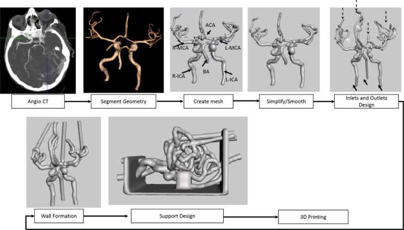
Complex phantoms require significant changes in the approach for STL file creation in order to make them practical. We created a phantom of the Circle of Willis and the surrounding vasculature down to one millimeter in diameter. The general workflow is shown in Figure 2 and the specific step details such as mesh error handling and features addition are described in Figures 3, 4, and 5. Since the vascular area of interest is much larger and requires an injection through all the vessels leading to the brain, we started with a CT-angio acquisition. As in the case of the small phantoms, vasculature was segmented using a 3D station (Vital Images, Minneapolis MN). For vessel areas located near bone structures, such as the carotid syphon, vessel segmentation was inaccurate and required manual lumen outlining. Next we exported the geometry as 3D meshes in a Stereo-Lithographic (STL) File, which was uploaded in a mesh manipulation software (www.MeshMixer.com).[10]
Figure 2.
Flow diagram showing the steps performed in order to obtain a STL file for a complex phantom needed for the 3D printer (ICA-internal carotid, BA- Basilar Artery, MCA- Middle Cerebral Artery, ACA- Anterior Communicating Artery)
Figure 3.
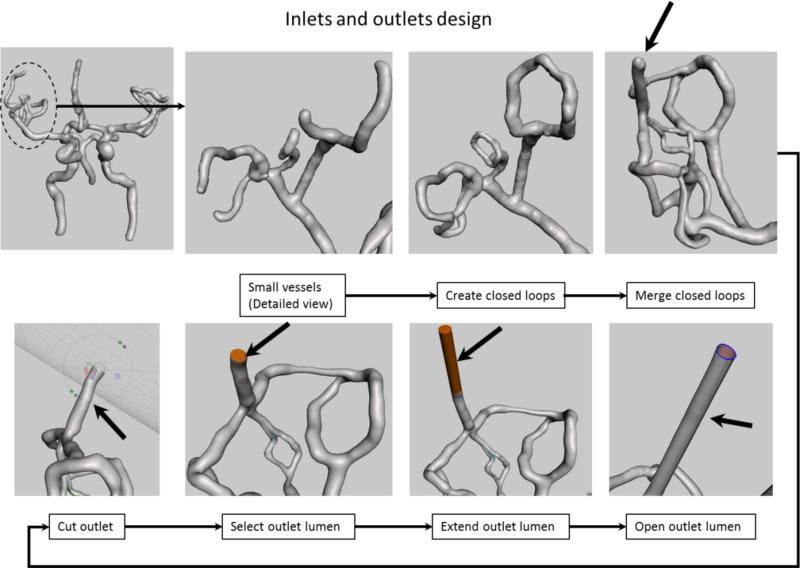
Inlet and outlet design: We show the manipulation of the outlets corresponding to the right Middle Cerebral Artery Region (dotted circle). Top row shows creation of closed loops to reduce the number of outlets. Bottom row shows an extension example of one of the outlet (black arrow on last view top row) for practical reasons. The model orientation in the lower row was changed to give a better view of the intermediate steps required to extend this particular outlet (black arrow).
Figure 4.
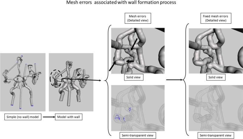
Extrusion and errors associated with this process. Mesh errors are shown for the area outlined by the dashed circle. In the solid model the errors location is indicated by the black arrows, however in this view the errors are not visible. In the x-ray view of the model the errors due to the mesh self-intersection after extrusion are automatically identified and shown as blue curves.
Figure 5.
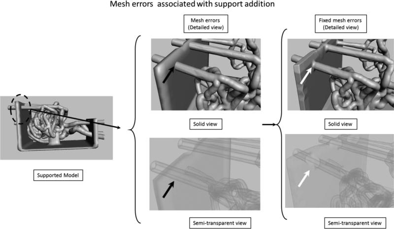
Support addition details. Mesh errors (black arrows) are not recognized by the mesh manipulating software. In the x-ray view it can be seen that the outer mesh of the phantom is intersecting the outer mesh of the support structure. The STL for the printer requires a continuous surface (if you start from one point one could reach any other point on the model, including vessel lumen). In the final view, at the location of the white arrows, the redundant surfaces were fixed, the outer wall of the mesh is merged with the support wall.
Multiple outlets pose a practical problem in establishing a facile and reliable flow loop used during contrast-based imaging, device testing or flow evaluation. We reduced the number of outlets by merging the small vessels in closed loops (white arrows in the 5th step of Figure 2). The step by step workflow is shown in Figure 3. First we closed the smallest branches into closed flow loops using a mesh growing tool and readjusting the mesh position. Once the loops were established, we merged them using the same mesh manipulation technique. We repeated the procedure until only one outlet was established for a given group in a cerebral region (e.g. Left Middle Cerebral Artery region). We extended each outlet and inlet using a technique shown in the bottom row of Figure 3. We placed a cutting plane over each outlet. We adjusted the plane at the desired location and orientation and removed a small tip of the vessel. This process creates a new surfaces corresponding to the lumen. We selected the newly created surface and extruded it in a direction normal to the surface for a given distance. In the final part of this processing step, we eliminated the lumen surface for each inlet and outlet (Figure 3, bottom row). Without this particular step, it is not possible to add a wall to the phantom during the extrusion process. The process was done for each outlet and the inlet.
As shown in Figure 1 (3rd STL Model), the next step in the phantom design is to add a wall. We selected the entire mesh and extruded in a direction normal to each triangle surface for two millimeters. This operation creates a new surface connected with the initial one. For complex phantoms, normal extrusion can be associated with some mesh errors. The most common errors are mesh surface intersections (Figure 4). In the area around bifurcations or sharp corners, the extruded surface will intersect itself causing errors. In figure 4, we show both a solid image and an semitransparent view of the phantom. Intersecting surfaces can be observed as blue curves in the x-ray view of the phantom and they are identified automatically by the software. To fix the errors we reduced locally the number of mesh triangles followed by re-meshing.
After this step, the structure is ready to be printed; however when using rubber-like material the entire structure is too fragile and requires extra support. We built a support platform in SolidWorks and saved it as an STL file which was next imported into the mesh manipulation software. The mesh structures of the phantom and the support structure were aligned manually (Figure 5). After alignment the surfaces of the two structures intersect as shown in the Figure 5 detailed semitransparent. We manually fixed these errors by deleting redundant surfaces and merging the outer surfaces. If such errors are not fixed properly the lumen of the vessels will be occluded where support structure intersects with the phantom. After this step, the phantom is ready for printing/manufacturing.
2.1.2. 3D Printing and phantom preparation
We used an Objet PolyJet 3D printer, Model260 V (Objet-Stratasys, Inc. Eden Prairie, MN) to manufacture the phantoms. The printer has a choice of 17 materials, and can print ultrafine 16 micron layers, which is ideal for fine detail, complex geometries and very thin walls. For rigid materials, the accuracy in each printed plane is between 20-85 μm for features smaller than 50 mm; and up to 200 μm for full model size. The net printing area is 255 × 252 × 200 mm. For soft materials, the layer resolution is about 32 μm and up to 200 μm in-plane accuracy.
For the 3D printing we used two materials and one common support; the chemical compositions as described in the material safety data sheet (MSDS) are shown in Table 1. The first material is transparent and very hard, and behaves similar to an acrylic. The second printing material is elastic and semi-transparent and behaves as polyurethane. The mechanical properties of the materials are listed in Table 2.
Table 1.
Materials used for phantom manufacturing
| VeroClear (Hard Material) | TangoPlus (Soft Material) | SUP705 (Support Material) | |
|---|---|---|---|
| Chemical Composition | Isobornyl acrylate Acrylic monomer Urethane acrylate Acrylic monomer Epoxy acrylate Acrylate oligomer Photoinitiator |
Urethane acrylate oligomer Methacrylate oligomer Exo-1,7,7-trimethylbicyclo[2.2.1]hept-2-yl acrylate Resin, polyurethane Photoinitiator |
1,2-Propylene glycol Polyethylene glycol Acrylic monomer Glycerin Photoinitiator |
Table 2.
Mechanical properties of the materials
| VeroClear (Hard Material) | TangoPlus (Soft Material) | |
|---|---|---|
| Tensile strength (psi) | 50-65 | 0.8-1.5 |
| Elongation at break (%) | 10-25 | 170-220 |
| Modulus of elasticity (psi) | 2000-300 | N/A |
| Compressive set (%) | N/A | 4-5 |
| Tensile tear resistance (Lb/in) | N/A | 2-4. |
After printing, the first step is removal of the support material. A 5 mm tube connected to a power-washer was used to remove the material inside the large vessels. The tube connected to the power washer was inadequate for small vessels (<2mm) or very tortuous regions such as the carotid syphon. To clean such areas, we used various catheters between 4 French and 7 French, connected directly to a water faucet. Even in these conditions some material was hard to remove, so in a third step, we soaked the samples in sodium hydroxide solution for 24 hours and repeated the cleaning using a small diameter catheter. In a final step, to remove the small particles of support material, we connected the phantom to a peristaltic pump (Masterflex L/S Cole Parmer Vernon Hills, IL) and ran it at high speed for approximately one hour, using the same sodium hydroxide solution.
Due to the finite resolution, the models have a very fine structure which reduces the material transparency. The acrylic-based phantoms react slightly with acetone. To increase the transparency, we connected the acrylic vascular phantoms to an acetone vapor flow circuit. Acetone was placed in a beaker connected to an air duct and placed in a water bath which was heated to a 65 °C.
2.2 Phantom Testing
Phantoms were tested in three steps: x-ray imaging, procedure simulations and cone-beam CT for geometry accuracy verification. Each phantom was connected to a peristaltic pump (Masterflex L/S Cole Parmer Vernon Hills, IL) and planar and rotational angiography was performed on each one. For complex phantoms we focused on the vessel patency and qualitative assessment of the flow.
Mechanical testing consisted of performing a clot retrieving procedure in the case of an ischemic stroke. We connected the phantom to a pulsatile pump and placed blood clots in the Middle Cerebral artery region using a 6 French catheter. We made the clots by mixing 4 ml fresh rabbit blood (no anti-coagulant), 32 mg fibrinogen from bovine plasma (Sigma-Aldrich, F8630), 1 Unit of thrombin from bovine plasma (Sigma-Aldrich, T4648) in a 5 ml syringe for at least 3 minutes. The solution was placed into plastic tubing (4 mm diameter) and incubated at room temperature for at least 60 minutes. Various clots with different lengths were made by cutting the tubing. The clots had a soft, gel-like, consistency; they were loaded in a syringe and flushed through a guide catheter into the main flow. Once placed into the flow, the clot traveled until it got stuck, obstructing the arterial circulation in the distal vessels. Using this method we could block various vessels by controlling the clot size. We acquired digital subtraction angiography data pre- and post-clot placement and after the clot removal procedure. A neurosurgeon performed multiple clot retrieval procedures using x-ray image guidance. First, a 6 French Neuron catheter (Penumbra Inc. Alameda CA) was placed in one of the carotids for support; using the support catheter the surgeon advanced a 3 French Rebar micro-catheter (Covidien, Plymouth MN) and navigated through the occluded segment. A revascularization device, Solitaire (Covidien, Plymouth MN) was advanced to the clot location. Keeping the device in place, the neurosurgeon retrieved the micro catheter until the device was fully deployed (unsheathed). After a short waiting period, the device was retrieved while a second interventionist applied a negative pressure on the 6 French guide catheter. Finally the vessel patency was verified using DSA.
To verify the accuracy of the phantom-making process, we scanned the new phantom geometries using rotational DSA. The two aneurysm phantoms were connected to a flow loop in an angiographic suite and rotational angiography was performed. New STL files were created and compared with the initial patient specific meshes, 2nd STL Model, Figure 1. Differences in geometry were quantified using CloudCompare [11], a 3rd party software.
3. Results
Simple phantoms, Figure 6, which require one inlet and a maximum of 2 outlets are straightforward. Using the 3D workstation and minimal mesh manipulation, we were able to create the STL file in less than 20 minutes.
Figure 6.
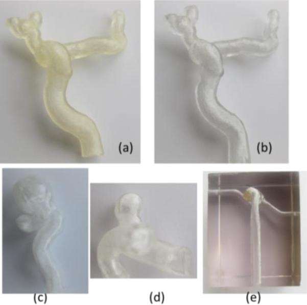
Patient specific vascular phantoms: (a) carotid phantom using elastic material, (b) carotid phantom using hard transparent material, (c) carotid syphon aneurysm phantom (hard material), (d) internal carotid artery aneurysm phantom (hard material), (e) basilar aneurysm phantom embedded as a hollow structure in a hard material.
The printing process for such simple phantoms was short, less than twenty minutes. The printer head is required to make a twenty centimeter translation regardless, so manufacturing more than one phantom comes with no time cost, as long as the phantoms do not extend outside the printing head size which is about 5 centimeters wide.
The complex phantom required nine and a half hours of continuous manufacturing. Overall mesh manipulation for complex phantoms, Figure 7, is a very tedious process; the complex phantom containing the entire Circle of Willis required nearly twenty hours of work by an experienced image processing scientist. The final design which emerged after a few iterations and interactions with neurosurgeons contained three million vertices and six million triangles.
Figure 7.
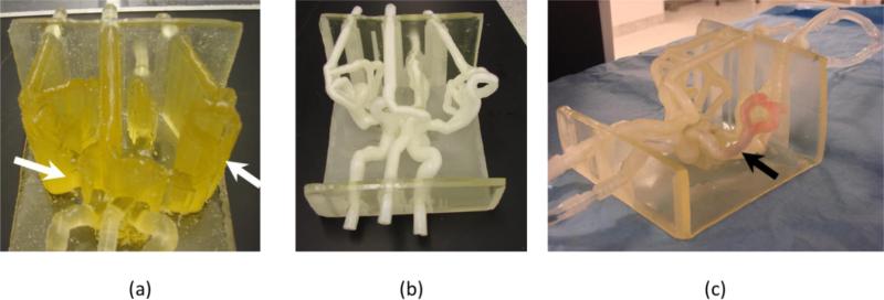
Complex phantom: (a) phantom embedded in support material indicated with white arrows, (b) phantom after the material has been removed, (c) phantom in a flow loop, black arrow shows location of a blood clot.
After manufacturing, the support material needs to be removed. Removal of the support materials from small vessels, tortuous regions or aneurysms was the greatest challenge we experienced for both kinds of phantom - simple and complex. Many of the carotid phantoms, Figure 6(a) and 6(b), had to be passed through 4-5 cycles of 24 hours soaking in sodium hydroxide solution followed by water pressure washing. For the complex phantoms, the post print processing of the phantom is a far more challenging process. In figure 7 (a) we show the Circle of Willis phantom after printing; most of the structures are embedded in support material (Figure 7, a white arrows), including the arterial lumen. Such a phantom required about 15 hours of work until all the vessels were cleaned. After cleaning and soaking in sodium hydroxide solution, the vessels have a white color which resolves partially in time Figure 7 (c).
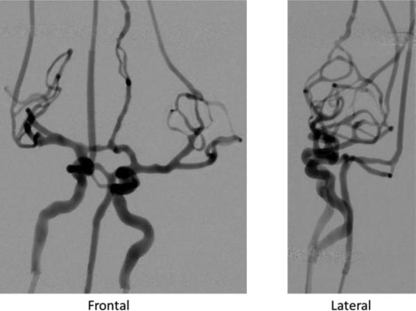
Angiography using iodinated contrast injection showed vessel and aneurysm patency for all phantoms; attenuation due to the material was negligible. The DSA acquisition for the complex phantom is shown in Figure 8. The x-ray settings were 80 kVp, 32 mA and 11.8 ms for the frontal view and 73 kVp, 20 mA and 10.2 ms for the lateral.
Figure 8.
DSA runs of complex neuro-phantom using a bi-plane C-arm angiographic system. All small vessels are patent.
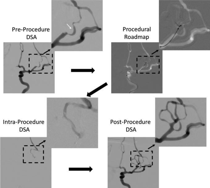
Images acquired during the clot retrieving procedure performed in the complex phantom (Figure 7) are shown in Figure 9. The pre-procedure DSA run was done right after the clot placement in the left middle cerebral artery. When compared with the frontal DSA in Figure 8 it can be seen that an entire section of the circulation was blocked. Using the DSA run, a vasculature road map was created and used for micro-catheter advancement. Guidance was done using biplane fluoroscopy. The x-ray parameters were 70 kVp, 17 mA and 2.7ms for frontal view and 70 kVp, 12 mA and 2.2 ms for lateral view. Once the micro-catheter was advanced distal to the clot location, the neurosurgeon performed a DSA acquisition by injecting contrast into the micro-catheter. This is in general the protocol for real cases to verify if the catheter is inside the arterial lumen. The desired result is to see slight pooling of the contrast. Using this phantom such behavior was observed. Finally the clot was removed and the post-procedure DSA shows patency of the vessels.
Figure 9.
Clot retrieving procedure: Large black solid arrows indicate the steps in which the procedure was performed.
Mechanical behavior of the catheter and the back pressure sensed by the interventionist were very similar to that experienced clinically. Clots were easy to deliver at the desired location and they were not removed by the flow in the system. Sometimes clot fragmentation occurred because of the procedure and resulted in blockage of more distal branches. This is a situation which is seen in some cases.
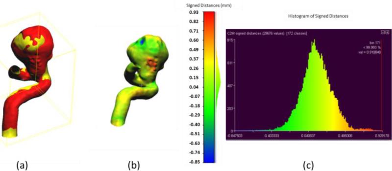
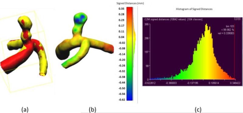
Accuracy of the phantom fabrication process is exemplified in Figures 10 and 11. For this comparison we used the aneurysmal phantoms (c) and (d) from Figure 6. The phantoms were connected to a flow loop for a rotational angiography acquisition and cone-beam CT reconstruction. The 3D STL file obtained after the rotational angiogram (red) was compared with the 2nd STL model (Figure 1) (yellow). Difference comparisons between the two models are shown on the colored map, Figures 10 (b) and 11 (b) and explicitly described using the histograms in Figures 10(c) and 11(c). The majority of points of comparison have low (near zero) error. Both the maximum and minimum error occur within the aneurysm dome which may indicate residual support material still present within the reconstructed mode.
Figure 10.
Accuracy of phantom fabrication for a carotid syphon aneurysm: (a) Overlain images of reference model (yellow) and reconstructed comparison model (red); (b) Comparison of differences between two models as shown on the reconstructed model with light green representing zero difference; (c) Histogram of differences between reference and reconstructed models (abscissa in mm).
Figure 11.
Accuracy of phantom fabrication for an internal carotid artery aneurysm: (a) Overlain images of reference model (yellow) and reconstructed comparison model (red); (b) Comparison of differences between two models as shown on the reconstructed model with yellow representing zero difference; (c) Histogram of differences between reference and reconstructed models (abscissa in mm).
4. Discussions
We presented the workflow to create patient specific vascular phantoms using Polyjet 3D printers followed by a set of tests designed to show the accuracy of the process and functionality. The results presented here indicate that the most challenging part of the manufacturing process remains the workflow in the pre- and post-print phases. Despite these challenges the phantom manufacturing using this technology is very detailed and accurate. In addition the qualitative evaluation of the procedure in a complex patient specific phantom done by neurosurgeons was very well regarded. The feel and the catheter behavior were very similar to a real case.
To manufacture the phantoms we started with 100 μm walls, which the printer was able to manufacture with high accuracy. However, the mechanical handling during support material removal damaged these phantoms. We incremented the walls until the phantoms were able to withstand the pressure of the water jet without getting damaged. After extended usage, the inlet of the soft phantoms can be damaged, depending on the size of the connectors used. We found out that silicone caulking works very well; in addition the silicone and the soft printing material have about the same tensile strength. We were not able to create complex phantoms mimicking the circle of Willis using hard material such as VeroClear due to difficulties in removing the support material from the small tortuous vessels.
Previously reported phantoms [12-16] were very simple and most of the time difficult to produce. While our approach has its challenges, it eliminates and simplifies certain aspects of the phantom manufacturing process. Prior investigations used simplistic approaches to create patient specific geometries to evaluate new devices[17] or well established ones. [14, 18]. While such approaches are needed in order to report device behavior in a reproducible setup, they lack the true test of the clinical situations such as delivery through a realistic arterial geometry. The 3D printing offers new possibilities of testing not only of devices but also the surgical procedure. This in itself could lead to a new paradigm as to how interventional procedures are done in a clinical environment.
Despite the current limitations of the processes, the accurate phantoms generated could be used both to study physiological aspects of the vascular disease and test new endovascular device performance. In addition they could be used for training of beginning neurosurgeons and interventionist or for the development of new interventional procedures and devices.
5. Conclusions
We present a logical workflow for data acquisition, processing and creation of patient specific vascular phantoms. The post-printing cleaning process of material support used by the 3D Polyjet printers can present difficulties when dealing with a tortuous phantom or small vessels (less than 2 mm). Phantom sides exposed to the support material are in general mat and require sanding and chemical processing to increase transparency. Despite these obstacles, the phantom models are extremely accurate; the geometry differences between the phantom and the patient geometry were of the order of the voxel size, less than 125 microns. This benefit makes this technology very useful for device development testing and medical research.
Acknowledgments
This work is supported by NIH grant 2R01EB002873 , equipment from Toshiba Medical System Corp and software support from Vital Images Inc. We would like to than Liza Pope for blood clot preparations, Setlur Nagesh for assistance during clot retrieval experiments and Megan Russ wit assistance in phantom manufacturing.
References
- 1.Go A,S, Mozaffarian D, Roger V,L, Benjamin E,J, Berry J,D, Borden W,B, Bravata D,M, Dai S, Ford E,S, Fox C,S, Franco S, Fullerton H,J, Gillespie C, Hailpern S,M, Heit JA, Howard V,J, Huffman MD, Kissela BM, Kittner SJ, Lackland DT, Lichtman JH, Lisabeth LD, Magid D, Marcus GM, Marelli A, Matchar D,B, McGuire D,K, Mohler E,R, Moy C,S, Mussolino M,E, Nichol G, Paynter N,P, Schreiner P,J, Sorlie P,D, Stein J, Turan T,N, Virani S,S, Wong N,D, Woo D, Turner M,B, American Heart Association Statistics, C. Stroke Statistics, S. Heart disease and stroke statistics--2013 update: a report from the American Heart Association. Circulation. 2013;127(1):e6–e245. doi: 10.1161/CIR.0b013e31828124ad. [DOI] [PMC free article] [PubMed] [Google Scholar]
- 2.Hayes P,D, Sadat U, Walsh S,R, Noorani A, Tang T,Y, Bowden DJ, Gillard J,H, Boyle J,R. Cost-effectiveness analysis of endovascular versus open surgical repair of acute abdominal aortic aneurysms based on worldwide experience. J Endovasc Ther. 2010;17(2):174–82. doi: 10.1583/09-2941.1. [DOI] [PubMed] [Google Scholar]
- 3.Molyneux A,J, Kerr R,S, Yu L,M, Clarke M, Sneade M, Yarnold J,A, Sandercock P, International Subarachnoid Aneurysm Trial Collaborative, G. International subarachnoid aneurysm trial (ISAT) of neurosurgical clipping versus endovascular coiling in 2143 patients with ruptured intracranial aneurysms: a randomised comparison of effects on survival, dependency, seizures, rebleeding, subgroups, and aneurysm occlusion. Lancet. 2005;366(9488):809–17. doi: 10.1016/S0140-6736(05)67214-5. [DOI] [PubMed] [Google Scholar]
- 4.U.S. Department of Health. Human Services, F. A. D. A. Innovation or Stagnation? 2004. Challenge and Opportunity on the Critical Path to New Medical Products. Washington D.C.: 2004. [Google Scholar]
- 5.Sonka M, Fitzpatrick M. Handbook of medical imaging. Volume 2, Medical image processing and analysis. SPIE Press; Bellingham, Wash.: 2000. [Google Scholar]
- 6.Mut F, Cebral J,R. Effects of flow-diverting device oversizing on hemodynamics alteration in cerebral aneurysms. AJNR Am J Neuroradiol. 2012;33(10):2010–6. doi: 10.3174/ajnr.A3080. [DOI] [PMC free article] [PubMed] [Google Scholar]
- 7.Cebral J,R, Mut F, Raschi M, Scrivano E, Ceratto R, Lylyk P, Putman C,M. Aneurysm rupture following treatment with flow-diverting stents: computational hemodynamics analysis of treatment. AJNR Am J Neuroradiol. 2011;32(1):27–33. doi: 10.3174/ajnr.A2398. [DOI] [PMC free article] [PubMed] [Google Scholar]
- 8.Allard L, Soulez G, Chayer B, Qin Z, Roy D, Cloutier G. A multimodality vascular imaging phantom of an abdominal aortic aneurysm with a visible thrombus. Med Phys. 2013;40(6):063701. doi: 10.1118/1.4803497. [DOI] [PubMed] [Google Scholar]
- 9.Hsieh J, SPIE (Society) Computed tomography principles, design, artifacts, and recent advances. Wiley Interscience ; SPIE Press; Hoboken, N.J. Bellingham, Wash.: 2009. [Google Scholar]
- 10.MeshMixer. http://www.meshmixer.com/ (20 January 2014).
- 11.CloudCompare 3D point cloud and mesh processing software Open Source Project. http://www.danielgm.net/cc/ (20 January 2014).
- 12.Ionita C,N, Hoi Y, Meng H, Rudin S. Particle image velocimetry (PIV) evaluation of flow modification in aneurysm phantoms using asymmetric stents. Proc. SPIE. 2004;5369:295. doi: 10.1117/12.534274. [DOI] [PMC free article] [PubMed] [Google Scholar]
- 13.Ionita C,N, Suri H, Nataranjian S, Siddiqui A, Levy E, Hopkins N,L, Bednarek D,R, Rudin S. Angiographic imaging evaluation of patient-specific bifurcation-aneurysm phantom treatment with pre-shaped, self-expanding, flow-diverting stents: feasibility study. Proc. SPIE. 2011;7965:79651H–1. doi: 10.1117/12.877675. [DOI] [PMC free article] [PubMed] [Google Scholar]
- 14.Schafer S, Hoffmann K,R, Noël P,B, Ionita CN, Dmochowski J. Evaluation of guidewire path reproducibility. Medical physics. 2008;35:1884. doi: 10.1118/1.2903430. [DOI] [PMC free article] [PubMed] [Google Scholar]
- 15.Sherman J, Rangwala H, Ionita C, Dohatcu A, Lee J, Bednarek D, Hoffmann K, Rudin S. Investigation of new flow modifying endovascular image-guided interventional (EIGI) techniques in patient-specific aneurysm phantoms (PSAPs) using optical imaging. Proced-SPIE. 2008;6918:69181v. doi: 10.1117/12.772583. [DOI] [PMC free article] [PubMed] [Google Scholar]
- 16.Sherman J, Rangwalla H, Dohatcu A, Minsuok K, Ionita C, Rudin S. SU-FF-I-127: Patient Specific Angiography Phantoms for Investigating New Endovascular Image-Guided Interventional (EIGI) Devices. Medical Physics. 2007;34:2367. [Google Scholar]
- 17.Ionita C,N, Rudin S, Hoffmann K,R, Bednarek D,R. Microangiographic image guided local zation of a new asymmetric stent for treatment of cerebral aneurysms. Proc. SPIE. 2005;5744(1):354. doi: 10.1117/12.594789. [DOI] [PMC free article] [PubMed] [Google Scholar]
- 18.Schafer S, Hoffmann K, Walczak A, Ionita C, Noël P. SU-FF-I-63: Reproducibility of Guidewire Positioning and Stent Path for Endovascular Interventions. Medical Physics. 2005;32:1918. [Google Scholar]


