Abstract
Dilution of microfluidic droplets where the concentration of a reagent is incrementally varied is a key operation in drop-based biological analysis. Here, we present an electrocoalescence based dilution scheme for droplets based on merging between moving and parked drops. We study the effects of fluidic and electrical parameters on the dilution process. Highly consistent coalescence and fine resolution in dilution factor are achieved with an AC signal as low as 10 V even though the electrodes are separated from the fluidic channel by insulator. We find that the amount of material exchange between the droplets per coalescence event is high for low capillary number. We also observe different types of coalescence depending on the flow and electrical parameters and discuss their influence on the rate of dilution. Overall, we find the key parameter governing the rate of dilution is the duration of coalescence between the moving and parked drop. The proposed design is simple incorporating the channel electrodes in the same layer as that of the fluidic channels. Our approach allows on-demand and controlled dilution of droplets and is simple enough to be useful for assays that require serial dilutions. The approach can also be useful for applications where there is a need to replace or wash fluid from stored drops.
I. INTRODUCTION
Droplet-based microfluidic systems are emerging as an attractive platform to perform a variety of chemical and biological assays due to numerous benefits including small sample volume, short reaction time, high sensitivity, simple fabrication, and ease of automation.1–4 In any typical application, droplets of pico- to nanoliter volume containing the reaction agents are manipulated through the channels and one or more operations are performed at specified locations. Among the droplet operations, modifying the contents of a droplet through dilution or exchange of materials plays a vital role in applications involving serial dilutions. Serial dilution is a stepwise dilution process where the factor by which a substance is diluted in each step is constant. Serial dilutions are important in a variety of biological applications including protein crystallization,5,6 cytotoxicity assays,7–9 and dose-response analysis of drug compounds.10,11 Hence, the capability of serial dilution of microfluidic droplets is a highly desirable feature for conducting biological analysis in a lab-on-a-chip format.
Various microfluidic techniques have been reported in the literature for producing drops of varying chemical concentration. Song and Ismagilov12 demonstrated that by varying the flow rates of the constituents of the dispersed phase, droplets of varying concentration but of uniform volume can be generated. By designing an automated liquid presenting system and controlling the flow rates and duration of aspiration of liquids into a capillary, Du et al.13 generated linear arrays of droplets of varying size and concentration. A different design was proposed by Jambovane et al.14 to generate gradations of concentration in droplets. Instead of controlling the individual flow rates of the reagents, they controlled the dispensed volumes of the reagents by varying the timing of microvalves installed at respective channels so that each droplet contains a different amount of a reagent. Wegrzyn et al.15 developed a multilayer polycarbonate device with different combinations of fluidic resistances along the channels corresponding to the two sample liquids. Each combination of resistance results in specified flow rates which in turn produces a particular composition in the droplet. However, the flexibility in producing a wide concentration range is limited by the number of combinations of resistive paths, and the footprint of the device increases with the number of combinations. Miller et al.10 utilized the Taylor-Aris dispersion phenomenon to covert a pulse of a compound to a smooth gradient of concentration in the capillary before producing droplets of varying concentration of the compound.
A different approach to modify reagent concentration is to coalesce drops with different initial concentration. There have been a number of reports demonstrating various techniques for performing droplet coalescence. Broadly, there are two approaches to achieve coalescence of droplets in microfluidic devices: the passive and the active methods. In passive methods, a unique geometric feature in the device either slows down the drop speed and decreases the interdroplet spacing16–18 or temporarily immobilizes a droplet until the next one collides with it.19,20 While these methods are simple, the flexibility to achieve coalescence is limited because drop sizes, approach velocities (which dictates the time needed to drain the separating oil film), and the timing at which droplets can interact cannot be controlled independently. Moreover, since the merged droplet is removed from the site after binary collision, the concentration of every sample droplet is reduced by a factor of only two precluding serial dilutions.
Passive coalescence has also been demonstrated by utilizing the difference in size, viscosity,21 and interfacial tension22,23 between adjacent droplets. However, these techniques require careful control of the pumps to synchronize the target droplets of different properties, and the resulting dilution for each sample droplet is limited to a factor of two only. Generation of concentration gradient in moving and immobilized droplets was also demonstrated by Sun et al.24 and Sun and Vanapalli,25 respectively. Here, a long plug of liquid passively coalesces with trapped sample droplets and sequentially dilutes them producing a fine-gradation dilution. However, the coalescence time increases with the amount of surfactant and with high surfactant concentration coalescence does not occur at all. A microfluidic serial dilutor was demonstrated by Niu et al.26 for a single trap where the incoming droplet merges with the trapped droplet and ejects a droplet on the outlet side. Since the ejected droplet is of identical volume to that of the incoming droplet, the dilution factor (DF) per coalescence event is determined by the volumes of the trapped () and moving () droplets. Recently, Korczyk et al.27 also reported a microfluidic serial dilution device where droplets are generated and immobilized in traps, featuring multilayer channels of different cross-section, by controlling the rate and direction of liquid flow. The total range of achievable dilution is set by the total number of traps.
In many applications, it is necessary to have droplets stabilized by adding surfactant to the continuous phase. Drops are coated with surfactant to prevent biomolecule adsorption to channel walls, mitigate transport of compounds across the interface of the droplet, and improve the wettability to ensure smooth flow of droplets.28,29 In case of surfactant-added systems, the passive methods cannot be used for reliable coalescence of droplets. Hence, different active methods have been developed where an external energy source disrupts the droplet interfaces and forces them to merge together. Baroud et al.30 reported an infrared laser based selective coalescence of droplets where the tightly focused beam creates a gradient of surface tension due to thermocapillary action. Electric current induced heat has also been employed to cause coalescence of droplets in microfluidic channels.31 Recently, Xiang-ting et al. demonstrated that surface acoustic waves can also be used in microfluidic devices for droplet coalescence.32
Electric field mediated coalescence, termed as electrocoalescence (EC), has been demonstrated by a number of research groups. The advantages of EC are the controllability, simple peripheral components, and high potential for integration to portable lab-on-a-chip format. In EC based devices, the common feature is a pair of surface electrodes, either in simple rectangular design33–37 or interdigitated format,38–40 fabricated onto the lower substrate of the device. The electrodes, positioned at the specified location along the channel, are in direct contact with the fluid or passivated by a thin layer of insulating material. When energized, the spatial distribution of electric field generates electric stress on the interface owing to discontinuities in the permittivity and conductivity between the dispersed and continuous phases. If the electric stress is strong enough, it deforms the interface and enforces the coalescence.33,39
All of the active coalescence methods discussed above solely demonstrates binary drop coalescence limiting the final concentration of a sample droplet to be reduced by a factor of only two. However, assays based on serial dilution require gradations in compound concentration within drops, over a broad range. In addition, fine resolution in concentration gradation is essential for identifying accurately the dosage at which the target compound was effective. In this paper, we propose a microfluidic device featuring EC based dilution of a trapped droplet and capable of generating fine resolution in concentration gradient. The device has channel electrodes embedded into the same layer as that of the fluidic paths. This method simplifies the device fabrication by eliminating the steps involving metal deposition and etching and alignment of the substrate with the fluidic channels. Similar electrode design was used by Abate et al.41 for high-throughput injection of reagents to moving droplets. Picoinjection of reagents into moving droplets was also achieved using an electrode-less design.42 In both approaches, a combination of electrical stress and pressure is used to inject reagent, whereas in our method only electric field is required. In addition, the amount of injected reagent is constant for all the incoming droplets unless the pressure in the reagent channel or the droplet size is varied on the fly, making their approach less flexible for serial dilution assays, compared to our method.
II. BASIC PRINCIPLE AND DEVICE DESIGN
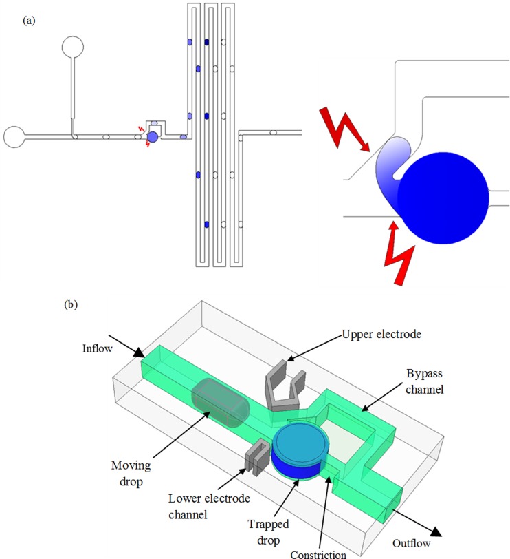
A schematic diagram, as shown in Figure 1(a), illustrates the concept of electrocoalescence based serial dilution of a trapped droplet. Surfactant covered droplets are generated at a T-junction and made to electrocoalesce with a trapped drop of defined initial concentration. The gradient of concentration can be generated either in the stream of moving droplets or in the trapped droplet by controlling the number of coalescence events. Figure 1(b) shows the three dimensional model of the microfluidic device used for the electrocoalescence based dilution of droplets. The main channel divides into two fluidic paths: the lower path consists of a cylindrical trap and a constriction along the main channel, and the upper path is the bypass having a rectangular cross-section. A segment of the bypass channel near the trap is inclined at 45° with respect to the main channel. The widths of the main channel, the bypass, and the constriction are 145 μm, 100 μm, and 40 μm, respectively. The diameter of the trap is 270 μm, and the volume of the trapped liquid is approximately 11.5 nl. The channel height is uniformly 200 μm in the device. The ratio between the hydrodynamic resistances of the trap and the bypass is 1.8. Thus, it is possible to fill the trap with the sample liquid according to a hydrodynamic feedback trapping mechanism43,44 or by fragmenting a long immiscible plug.24,45
FIG. 1.
Electrocoalescence-based serial dilution microfluidic device. (a) Schematic of the electrocoalescence based dilution process, showing the drop generation, electrocoalescence, and the serially diluted droplets (left). Because of electrocoalescence, the drops merge causing a two-way transfer of fluid (right). (b) The three-dimensional model showing the detailed design of the device. Widths of main channel, bypass, electrode channel, and trap are 145, 100, 50, and 270 μm, respectively. Channel heights are uniformly 200 μm in the device.
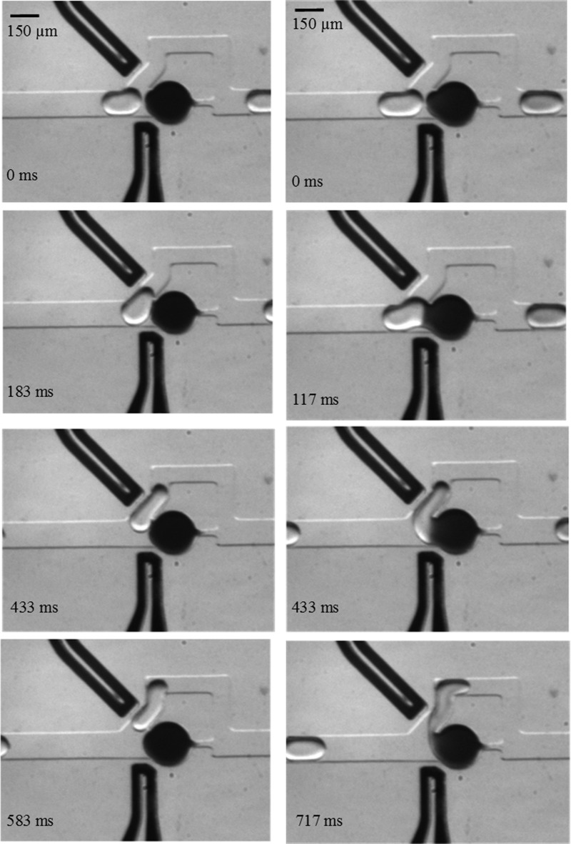
Once the trap is filled, the resistance along the lower path increases significantly causing the incoming droplets to follow the bypass. Figure 2 demonstrates the working principle of on-demand coalescence between the moving drop and the trapped drop. In the absence of electric field, the moving drop glides past the trapped drop. Although the interfaces are pushed against each other, shown by the deformation of the left-side interface of the trapped drop, coalescence due to hydrodynamic forces does not occur. However, in the presence of electric field, when the moving drop is near the trap, coalescence and material exchange take place. The liquid bridge resulting from coalescence remains until the tail of the moving drop tears off. The process of coalescence, followed by the break-up, does not affect the volume of the trapped or moving drops except the concentration. Thus, in our method, the electric field actuation does not need to be synchronized with droplet position, making it simple and free of feedback control.
FIG. 2.
Time-stamped images showing the operation of the microfluidic device. Left column: In the absence of electric field, the moving drop does not coalesce with the trapped drop, right column: With an applied electric field, coalescence occurs as the moving drop enters the bypass.
Electrodes are incorporated through the channels filled with liquid metal alloy in the same layer of PDMS (polydimethylsiloxane). In our device, the width of the electrode channel is 50 μm and the gap between the fluidic and electrode channels is 30 μm. This type of electrode design produces stronger electric field stresses than the surface electrodes embedded on channel floor, since the electric field lines pass through the fluidic channel and the field strength is uniform along any vertical plane. The electric field strength generated by the surface electrodes is non-uniform along any given vertical plane. Moreover, the liquid alloy-based electrodes can be designed such that the electric field lines are oriented along the desired direction that intensifies the deformation on both the trapped and moving droplets. This feature is illustrated in Figures 1 and 2, where the active portion of the upper electrode channel is parallel to the inclined portion of the fluidic bypass, and that of the lower electrode channel follows the profile of the main channel and the trap partially.
To investigate how the proposed design of the channel electrodes facilitates coalescence by generating electric field lines in the desired region, we performed simulations in COMSOL Multiphysics® 3.5. Since solving the coupled problem of hydrodynamics, drop deformation, and electrical stresses is quite challenging, we pursue a simpler route by taking representative static (deformed) drop shapes and calculating the resulting electric field distribution. As we discuss below, this simplified approach provides useful insights into regions where electrical stresses are strongest, thus aiding in device design and understanding the mechanisms of coalescence.
The capillary number (Ca) represents the relative strength of viscous forces over interfacial forces, and is given by , where is the carrier fluid velocity, is the carrier phase viscosity, and is the interfacial tension between the continuous and dispersed phases. The typical value of Ca in our system is 0.00137, which signifies that the interfacial forces dominate. The relative strength of the stress of electrical origin to that of interfacial origin is given by the electrocapillary number, , where is the permittivity of vacuum, is the dielectric constant of dispersed phase, is applied voltage, and is the distance between electrodes. In our system, , indicating that the magnitudes of both the electric stress and the interfacial stress are of the same order. Comparison between the charge relaxation time (, where is droplet conductivity) and the viscous relaxation time (, where is density, and is characteristic length) provides insights regarding the electrical and hydrodynamic processes, respectively. For the material properties and geometry in this study, and indicating the viscous process is very slow compared to the migration of induced charges towards the interface. Therefore, for a given position and shape of the moving droplet, electric field analysis provides a very good approximation of the coupled electrohydrodynamic analysis.
To execute the simulations, we used the quasi-electrostatics module and analyzed the time-harmonic in-plane electric current that includes the effect of the frequency of the applied voltage as well as the conductivities of the materials. The curvature of the liquid-liquid interfaces along the vertical plane was not considered, which allowed simplified analysis using the two-dimensional model of the geometry. Appropriate material properties were assigned to the subdomains and an electric potential difference of 50 Vac (5 kHz) was defined between the electrodes. All other interior boundaries were set to continuity of the current density and the exterior boundaries of the model were set to electric insulation. The conductivities of PDMS and the continuous phase were assumed to be zero, and the conductivity of the dispersed phase was set to 5.5 μS/m.
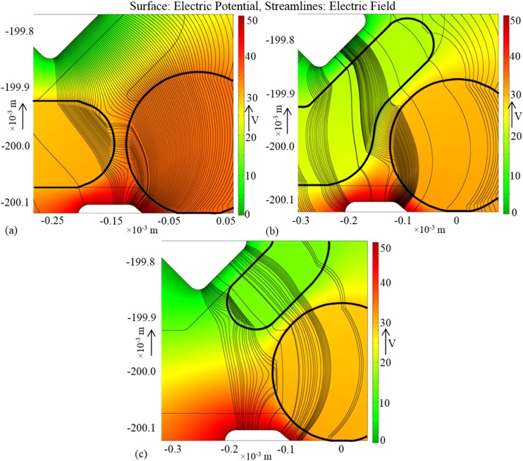
Coalescence between the moving and parked droplets starts near the region at the mid-plane of the main channel, since the droplets are closest in this region owing to the curvature of the interface. To induce coalescence, the electric field lines should penetrate into the channel and affect the regions of interfaces near the mid-plane. When the applied signal is DC or of low frequency, the potential of a droplet of ionic or aqueous liquid is constant due to the conductivity or polarizability of the liquid.46 This results in a strong electric field on the interface near the wall of the channel, and no field lines penetrate inside the droplets. The electric field near the wall causes only a change in the contact angle, which does not facilitate coalescence between the droplets. If an AC signal of moderately high frequency is applied, electric field lines are distributed inside the channel and the droplets and pass through both the droplets connecting the regions where the interfaces are closest.
Figure 3(a) shows the distribution of electric potential and field lines when the moving drop is at the junction of the trap and the bypass. Among the electric field lines connecting the two electrodes and passing through the region to the left of the wall between the trap and the bypass, a large number of lines penetrate both the drops. These are the lines along which the electric stresses act on the liquid-liquid interfaces, and the net effect is the deformation of the interfaces and the reduction of the continuous-phase film thickness. If the electric stresses are strong enough to bring the interfaces in contact and destabilize, the drops coalesce.33 The rest of the electric field lines is responsible for the change in contact angle of the drop on the channel walls. When the moving drop has entered the bypass escaping coalescence at its front end, shown in Figure 3(b), most of the electric field lines pass through both the drops and the continuous phase. The resulting forces deform the interfaces and are responsible for the coalescence at the body of the moving drop. Figure 3(c) portrays the scenario when the drop is inside the bypass having only the tail end in the region between the upper electrode and the trap. Since a significant number of field lines can still connect the interfaces on both drops and a liquid bridge below the PDMS wall—separating the trap from the bypass—is possible, coalescence can take place at the tail end of the moving drop.
FIG. 3.
Simulation results showing the distribution of electric potential (color) and field (streamlines) for three positions of the moving drop; (a) the droplet is close to the trap, (b) the droplet has partially entered the bypass, and (c) the droplet has entered the bypass, only the tail is in the active region.
III. MATERIALS AND METHODS
The PDMS microfluidic devices were fabricated using the standard soft-lithography.47 We used deionized water as the dispersed phase (diluting drops) and mineral oil (Sigma- Aldrich) containing 2% (wt/wt) Span-80 (Fluka) as the continuous phase (surface tension: 0.005 N/m). Black food color dye (McCormick) was diluted 20× by deionized water and used as the sample liquid for the trap. Drops were generated at a T-junction using syringe pumps (PHD 2000, Harvard Apparatus). Before starting the experiments, a liquid cartridge consisting of the sample plug, oil plug, and the diluting plug in the Tygon tube was prepared.24 One end of the tube was connected to the syringe (Gastight 1710, Hamilton) and the other end was connected to the hollow pin fitted to the inlet for the dispersed phase on the microfluidic device. The electrode channels were filled with eutectic gallium-indium alloy (Sigma-Aldrich) which is liquid at room temperature. A syringe was partially filled with the liquid electrode, followed by filling the channels by pressurizing the syringe. Electrical connections to the two electrode channels were made through metallic pins inserted into the respective inlets. We used a function generator (Agilent 33509B) to generate sinusoidal voltage signals, which were amplified by a high voltage power amplifier (Trek 2210). The two ends of the amplifier were connected to the electrodes in the device.
For each dilution experiment, the trap was filled with sample liquid first. Once all the sample liquid and oil has crossed the T-junction, droplets of diluting liquid were generated. We waited for the production of diluting drops to stabilize (typically 5 min) before the electric field was applied. We used a CCD camera (StreamView LR, SVSi) mounted on a stereo microscope (SZX16, Olympus, Japan) to record grayscale image sequences at 60 frames per second. The total intensity value of the trapped drop was calculated in MATLAB and the dilution fold was determined from the calibration between pixel intensity and dilution fold. The lowest concentration detectable by the camera was limited by the sensitivity of the sensor. We found that the pixel intensity corresponding to a 500× diluted droplet saturates the camera sensor.
IV. RESULTS AND DISCUSSION
We investigated the electrocoalescence based dilution in relation with different fluidic parameters and applied voltages. In particular, the dilution of trapped droplets was studied at different speeds and sizes of the moving droplets. The range of droplet speed and size that was accessible in experiments was limited by the reliability of the pump to generate steady flow rates as well as the allowable maximum pressure difference across the parked droplet to prevent it from squeezing through the trap. We characterized the effects of these parameters by plotting the DF, defined as the ratio between the concentration of the trapped droplet before any coalescence (Cp0) and that after coalescence (Cp).
A. Effect of capillary number on dilution
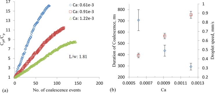
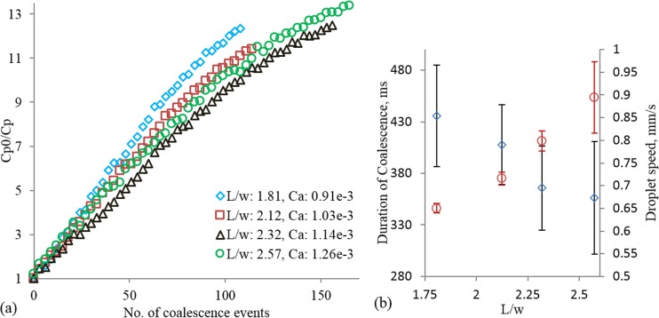
Figure 4(a) shows the DF as a function of number of coalescence events for three capillary numbers (Ca). The applied signal was a sinusoidal voltage of magnitude of 50 V and frequency of 5 kHz for all studies unless specified otherwise. In all the cases, the flow rate ratio between the oil phase (Qo) and the dispersed water phase (Qw) was kept constant at 3. This resulted in uniform size of diluting droplets, since it is well-known that the size of the droplets in a T-junction is a function of the ratio between the flow rates.26 The dilution factor is approximately linearly related to the number of coalescence events up to a large number of events. The linear relation between DF and number of events signifies that each moving droplet carries away equal amount of dye particles from the trapped droplet. However, we observed that the rate of dilution per coalescence event decreases towards the end (see Fig. 4(a)). The possible mechanism of equal amount of material transfer and the decline at large number of coalescence events is discussed in Sec. IV E.
FIG. 4.
Effect of capillary number on electrocoalescence based dilution. (a) Dilution factor as a function of the number of events for three capillary numbers; Qw/Qo = 0.33 for all the cases, (b) duration of coalescence (diamond) and droplet speed (square) for the three capillary numbers.
The linear relation between DF and number of coalescence events could be very useful in predictive dilution applications. It is also evident in Figure 4(a) that the dilution rate is higher for droplet flows characterized by lower Ca. At low Ca, the droplets travel at low speed allowing longer duration of coalescence, shown in Figure 4(b). As a result, the total material exchange in one coalescence event is also high. The underlying mechanism of material transfer during coalescence depends on: the local concentration of dye particles at the coalescing front of the trapped droplet immediately before the event and the advection-diffusion occurring in the merged droplet. The concentration near the front after an event is different from that in the bulk of the trap. Mixing of particles, influenced by molecular diffusion and flow inside the trap, continues until the next event. Thus, the higher dilution factor per event for low Ca is due to the homogenized concentration before each event and the favorable advection-diffusion of dye particles. The error bar for the duration coalescence is high for low Ca due to the fluctuation of flow-rate of the pump.
B. Effect of droplet size on dilution
We also investigated the effect of moving droplet size on the dilution factor per coalescence event. Here, the flow rate of the continuous phase was kept constant at 30 μl/h, while the flow rates of the dispersed phase were 10 μl/h, 15 μl/h, 20 μl/h, and 25 μl/h. The results, shown in Figure 5(a), confirm the general relation of the DF as a function of the number of coalescence events. It appears that smaller moving droplets dilute at higher rates than the larger droplets. However, since we did not control the size and speed (therefore Ca) independently (the average speed of the droplet increased with the size as shown in Figure 5(b)), the differences in the rate of change of DF for different droplet sizes could be simply due to the differences in Ca. This reasoning is supported by (i) the lower dilution factor observed with higher Ca in Figs. 4(a) and 5(a) and (ii) the reduced, rather than an increase in duration of coalescence with drop size as shown in Fig. 5(b).
FIG. 5.
Effect of droplet size on dilution. (a) Dilution factor as a function of droplet size for Qo = 30 μl/h and Qw = 10, 15, 20, and 25 μl/h. (b) The duration of coalescence (diamond) and droplet speed (circle) as a function of droplet length (L). w is the width of the channel.
It is noted that the results for Ca = 1.26 × 10⁻³ appear to deviate from the expectation in that the overall dilution profile lies above that corresponding to Ca = 1.14 × 10⁻³. However, the mean and standard deviation, as percentage of the mean value, of the duration of coalescence are 365 ms and 11.14% for Ca = 1.14 × 10⁻³ and 356 ms and 15.31% for Ca = 1.26 × 10⁻³. The variability in the duration of coalescence, when the mean values of durations are not statistically different, contributed to the exception in the result. This variability is caused by the fluctuations in the flow-rates and droplet size variation (standard deviation ∼7% of mean droplet length). In general, the standard deviations (11.25%, 9.5%, 11.14%, and 15.31%, respectively) as percentages of the mean values of duration are higher than those in the studies with constant droplet sizes (compare Figs. 4(b) and 5(b)). These higher standard deviations can be attributed to the larger sizes of droplets.
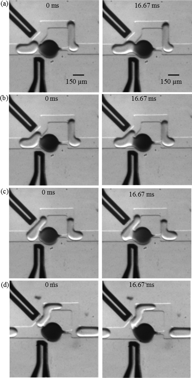
Further investigation revealed that the reason for variability in the coalescence duration with larger drops is due to different modes of coalescence. Depending on the position—along the body of the moving droplet—where coalescence occurs, we identified four types of coalescence and they are shown in Figure 6. In the “head” type coalescence, the interfaces fuse together as soon as the moving droplet is at the junction of the trap and bypass. This type of coalescence is desirable because the greatest dilution per droplet takes place due to the longest time available for material exchange. The “head” coalescence is typical for small moving droplets at low speed. In a given experimental condition, the type of coalescence varied from “head” to “body” types for longer droplets. The “tail” type coalescence occurs when a droplet is almost into the bypass and only the tail remains below the wall separating the trap and the bypass. Electric field lines passing through the trap and the tail of the moving drop can deform the interfaces near the separating wall and remove the oil film very quickly causing the coalescence. The resulting duration of material exchange is very short; however, it is highly uniform since the projected length of the tail is independent of the size of the droplet. The duration of coalescence and hence the rate of DF depend on the length of the droplet in all other types of coalescence.
FIG. 6.
Images showing different types of coalescence, (a) head, (b) upper body, (c) lower body, and (d) tail. Qo = 30 μl/h and Qw = 20 μl/h, applied voltage: 20 V.
The underlying mechanism that dictates the type of coalescence is not fully clear and needs further research. One of the possible reasons might be time dependent adsorption/desorption of the surfactant molecules on the interface of the trapped droplet. The mass exchange due to local flow profile and diffusion may result in the variation of surfactant concentration from one coalescence event to the next. Consequently, the duration of coalescence between two successive encounters varies while the distance between two adjacent moving droplets is fairly uniform. Another contributor to the types of coalescence is the variability in the drop size, which is ∼7% owing to fluctuations in the fluid flow rate.
C. Effect of voltage on dilution
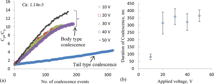
To investigate the effect of the magnitude of applied electric field on the dilution rate, we varied the amplitude of the voltage signal and maintained constant flow rates of the continuous and dispersed phases constant at 30 μl/h and 20 μl/h, respectively. The frequency of the applied signal was constant at 5 kHz. The results, shown in Figure 7(a), follow the same general pattern of DF as a function of the number of coalescence events. We did not observe any coalescence with voltages lower than 10 V. Consistently “tail” type coalescences were observed with an applied signal of 10 V. Due to the short duration of each coalescence, the rate of DF is very low, and the dilution was discontinued after ∼320 events. It is worth noting that due to the low but constant rate of dilution, this type of coalescence might be very useful in applications requiring fine resolution in the dilution factors over a small range. With higher applied voltages, the difference in the rate of dilution is negligible and can possibly be attributed to the variation in the durations of coalescence. As shown in Figure 7(b), the duration of coalescence is nearly constant for voltages greater than 10 V. This indicates that there exists a threshold voltage for achieving “body” type coalescence, and for the specified geometry and fluidic conditions, the threshold is 20 V.
FIG. 7.
Effect of applied voltage on dilution. (a) Results of dilution factor as a function of the number of coalescence events for different applied voltages; Qo = 30 μl/h and Qw = 20 μl/h. (b) The duration of coalescence as a function of applied voltage.
D. Investigation of the length of contact
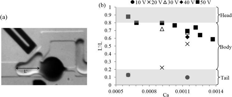
Since the amount of dilution per coalescence event also depends on the type of coalescence, it is important to identify the dominating parameter influencing the coalescence process. Here, we consider the total contact length of the moving droplet as an indicator of the type of coalescence. Figure 8 shows the mean contact length (L′) normalized by the mean droplet length (L) for different capillary numbers and applied voltages. Here, L′ is defined as the length along the longitudinal axis of the droplet from the contact point to the tail. Therefore, L′/L = 1 indicates coalescence at the front end of the moving droplet, whereas L′/L = 0 indicates coalescence at the tail end. However, these two values were not observed in our study due to the geometric features of out device. The front end of the moving droplet always enters and bends toward the bypass, driven by the significantly higher flow rate of the continuous phase compared to that through the trap, before the coalescence occurs and this is illustrated in Figure 6(a). When the droplet is fully into the bypass, the tip of the tail end has crossed the imaginary perpendicular line from the tip of the separating wall to the upper electrode. At this point, it is hydrodynamically infeasible to deform the interfaces to such a great extent and create a liquid bridge between the two droplets while the distance between them is continuously increasing.
FIG. 8.
Types of coalescence events based on the length of contact. (a) Image showing how the length of contact (L′) is measured and (b) the length of contact in coalescence normalized by the droplet length as a function of capillary number and applied voltages.
Thus, the feasible range of L′/L is between values greater than zero and less than one. Indeed, the maximum value we obtained from a “head” type coalescence is 0.88, and the minimum value is 0.1 that corresponds to the consistently “tail” type coalescence. For an applied voltage of 50 V, the L′/L decreases with the capillary number irrespective of the size of the moving droplet. This suggests that to achieve higher dilution fold from a fewer number of coalescence events the flow rates should be low. However, for 20 V the above trend was not observed, which could due to the variability in the droplet size as well as the weaker electric field.
E. Discussion
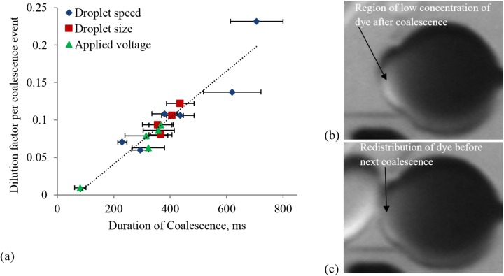
The general trend of dilution as a function of number of coalescence events is the same for all types of experiments. We find that the dilution rate is fairly constant for a significant number of coalescence events during the early phase. The dilution factor per event, , was found from the slope of the linear portion of the dilution profiles for different experiments. We considered 50 coalescence events as the limit of the linear trend. The maximum standard deviation of the error between the linear fit and data-points is found to be 0.11. Figure 9(a) shows the plot of dilution factor per coalescence event as a function of the duration of coalescence for different droplet sizes and speeds and applied voltages. The dilution factor per coalescence event is strongly correlated and monotonically increases with the duration of coalescence. If the initial concentration () in the parked drop is known, the concentration in the moving drop after a coalescence event can be estimated as , where and are the volumes of the parked and moving droplet, respectively, and is the slope of the linear portion of a given dilution profile.
FIG. 9.
(a) The dilution factor per coalescence event (α) as a function of the duration of coalescence process for different experimental conditions; (b) and (c) the images of the parked droplet showing the regions of low concentration of dye immediately after a coalescence event and just before the next event, respectively.
The linear portion of the profiles of dilution factor signifies that the amount of dye transfer in each of the coalescence events in this phase is constant. During coalescence, a circulatory motion near the periphery of the parked drop was observed. Moreover, the interval between successive events was shorter than the time needed for full mixing of the dye in the parked drop, indicating that the concentration distribution of the dye in the drop is non-uniform before a new coalescence encounter occurs. As a result, the low-concentration region of the parked drop is pushed away from the coalescing front by the circulating high-concentration mixture (see Figures 9(b) and 9(c)). However, after a large number of events, the concentration of dye decreases considerably resulting in the gradual decrease in the rate of dilution per coalescence event towards the later phase. From image analysis, we found that the total intensity of the parked droplet gradually decays after a coalescence event until the next event. This decay corresponds to the mixing and redistribution of dye particles. The estimated time for full mixing, corresponding to the time needed to reach a plateau, is ∼1600 ms. However, the typical time interval between successive incoming droplets was ∼300 ms. It is possible to implement drop-on-demand generator48 to control the time interval between drops independently of drop size, enabling full mixing within the parked drop, before the next coalescence event.
We observed different types of coalescence depending upon the position along the body of the moving drop where coalescence starts. For smaller drops, the variation in the type of coalescence is not significant even if the capillary number changes by a factor of two. But for larger droplets, the type of coalescence varies considerably between “head” and “body” types. Different types of coalescence result in different amounts of dye transfer. We observed dilution factor per coalescence event to be as low as 0.0096 due to “tail” type and as high as 0.232 for “head” type coalescence. Thus, by controlling the type of coalescence, the dilution rate can be controlled.
The variation in the type of coalescence for a given droplet size and speed is likely due to the variation in the interfacial tension at the parked drop-oil interface that could lead to Marangoni flows and therefore fluid circulation within the drop. The spatial variation of interfacial tension depends on the distribution of surfactant at the interface, where the distribution could result from both advection-diffusion and adsorption-desorption mechanisms. The average interval between successive coalescence events in our experiment was ∼300 ms. Based on the concentration of surfactant used in this study, the approximate adsorption and desorption time scales are found to be ∼1.14 ms and ∼0.146 × 10⁶ s, respectively.49 Thus, the characteristic adsorption time is much shorter whereas that of desorption is much longer than the typical interval between two successive coalescence events. This indicates that the difference in the type of coalescence for a given experimental condition is most likely not due to adsorption-desorption phenomena. Instead, we find using ring tensiometry that the dye particles act as surfactants because the interfacial tension decreases from 45.6 mN/m for no dye to 2.6 mN/m for 1% (wt/wt) black dye in water. Thus, it is possible that the coalescence-induced hydrodynamics and the diffusion of black dye driven by the local concentration gradient in the parked drop play major roles in the variation of interfacial tension on the coalescing front from one event to another. Probing these mechanisms could be a subject of future investigations.
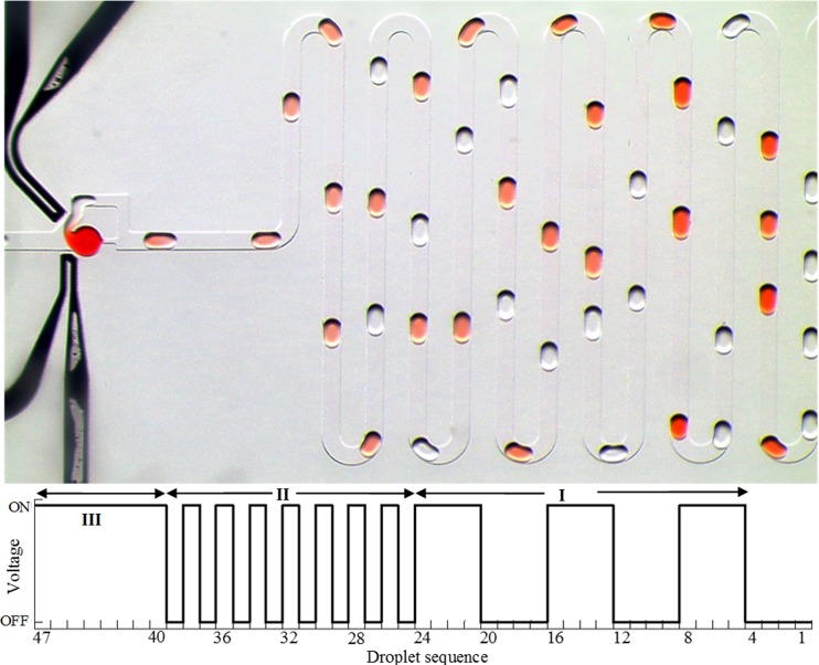
Nevertheless, the proposed method can be used for advanced applications requiring on-demand dilution, and Figure 10 demonstrates such function. First, the electric field was alternately switched on or off for four consecutive droplets. Thus, four consecutive droplets coalesced with the parked droplet whereas next four droplets did not coalesce with the parked droplet. Second, the electric field was alternately switched on or off such that every other moving droplet coalesced with the parked droplet. Finally, the field was kept on so that every moving droplet coalesced with the parked droplet. It is also possible to add more functionality by incorporating multiple traps storing different sample liquid for on-demand storage and multiplexed dilution and mixing.
FIG. 10.
Photograph showing on-demand coalescence and dilution. Actuation phase I: electric field was turned on or off for four droplets; actuation phase II: every other droplet coalesced; actuation phase III: electric field is on for all the droplets.
V. CONCLUSIONS
Electrocoalescence based dilution of a trapped droplet has been investigated. The fractional dilution of the trapped droplet per coalescence event was studied for different droplet size, speed, and applied voltages. Results show that dilution is strongly influenced by the characteristic capillary number. At low capillary numbers, the coalescence is mainly “head” type, although fluctuations in the flow rate as well as the variations in droplet size affects the duration of coalescence. The duration is uniform in case of “tail” type coalescence which might be utilized in applications requiring very small amount of dilution. The microfluidic device proposed here does not require any additional fabrication process for the electrodes. The electrodes are formed by the liquid-metal alloy filling the appropriately designed channels.
Although the thickness of PDMS layer separating the electrodes and the fluidic channel was 30 μm, consistent coalescence was achieved with 10 V. This demonstrates the potential of the current design for a portable lab-on-a-chip which might be operated by a battery. The design proposed here can be adapted to serial dilution applications requiring fine gradation of dilution between successive coalescence events. Since the electric field can be turned on or off very fast, on-demand coalescence and dilution with any sequence of moving droplets can be performed with this device. The proposed method can also be used in applications requiring washing or reagent exchange from stored droplets containing particles or cells.50 We envision that cells could be stored in a series of trapped drops24 and media exchange could be achieved by introducing train of moving drops that coalesce with the trapped drops. If simultaneous washing or exchange is needed, all the positive (and negative) electrodes near traps can have a single connection without complicating the design and operation. In addition, active control of the applied field can be automated by implementing a droplet sensing mechanism in front of the trap.
ACKNOWLEDGMENTS
This research was funded by NSF CAREER Award (No. 1150836). B.B. was partially supported by NSF Grant No. 1124814.
References
- 1.Dressler O. J., Maceiczyk R. M., Chang S.-I., and DeMello A. J., “ Droplet-based microfluidics enabling impact on drug discovery,” J. Biomol. Screen. 19, 483–496 (2014). 10.1177/1087057113510401 [DOI] [PubMed] [Google Scholar]
- 2.Tran T. M., Lan F., Thompson C. S., and Abate A. R., “ From tubes to drops: droplet-based microfluidics for ultrahigh-throughput biology,” J. Phys. D: Appl. Phys. 46, 114004 (2013). 10.1088/0022-3727/46/11/114004 [DOI] [Google Scholar]
- 3.Schneider T., Kreutz J., and Chiu D. T., “ The potential impact of droplet microfluidics in biology,” Anal. Chem. 85, 3476–3482 (2013). 10.1021/ac400257c [DOI] [PMC free article] [PubMed] [Google Scholar]
- 4.Joensson H. N. and Svahn H. A., “ Droplet microfluidics—A tool for single-cell analysis,” Angew. Chem. 51, 12176–12192 (2012). 10.1002/anie.201200460 [DOI] [PubMed] [Google Scholar]
- 5.Zheng B., Tice J. D., Roach L. S., and Ismagilov R. F., “ A droplet-based, composite PDMS/glass capillary microfluidic system for evaluating protein crystallization conditions by microbatch and vapor-diffusion methods with on-chip X-ray diffraction,” Angew. Chem. 43, 2508–2511 (2004). 10.1002/anie.200453974 [DOI] [PMC free article] [PubMed] [Google Scholar]
- 6.Li L. and Ismagilov R., “ Protein crystallization using microfluidic technologies based on valves, droplets and SlipChip,” Annu. Rev. Biophys. 39, 139–158 (2010). 10.1146/annurev.biophys.050708.133630 [DOI] [PubMed] [Google Scholar]
- 7.Barbulovic-Nad I., Yang H., Park P. S., and Wheeler A. R., “ Digital microfluidics for cell based assays,” Lab Chip 8, 519–526 (2008). 10.1039/b717759c [DOI] [PubMed] [Google Scholar]
- 8.Yu L., Chen M. C., and Cheung K. C., “ Droplet-based microfluidic system for multicellular tumor spheroid formation and anticancer drug testing,” Lab Chip 10, 2424–2432 (2010). 10.1039/c004590j [DOI] [PubMed] [Google Scholar]
- 9.Brouzes E., Medkova M., Savenelli N., Marran D., Twardowski M., Hutchison J. B., Rothberg J. M., Link D. R., Perrimon N., and Samuels M. L., “ Droplet microfluidic technology for single-cell high-throughput screening,” Proc. Natl. Acad. Sci. U.S.A. 106, 14195–14200 (2009). 10.1073/pnas.0903542106 [DOI] [PMC free article] [PubMed] [Google Scholar]
- 10.Miller O. J., Harrak A. E., Mangeat T., Baret J.-C., Frenz L., Debs B. E., Mayot E., Samuels M. L., Rooney E. K., Dieu P., Galvan M., Link D. R., and Griffiths A. D., “ High-resolution dose–response screening using droplet-based microfluidics,” Proc. Natl. Acad. Sci. U.S.A. 109, 378–383 (2012). 10.1073/pnas.1113324109 [DOI] [PMC free article] [PubMed] [Google Scholar]
- 11.Agresti J. J., Antipov E., Abate A. R., Ahn K., Rowat A. C., Baret J.-C., Marquez M., Klibanov A. M., Griffiths A. D., and Weitz D. A., “ Ultrahigh-throughput screening in drop-based microfluidics for directed evolution,” Proc. Natl. Acad. Sci. U.S.A. 107(9), 4004–4009 (2010). 10.1073/pnas.0910781107 [DOI] [PMC free article] [PubMed] [Google Scholar]
- 12.Song H. and Ismagilov R. F., “ Millisecond kinetics on a microfluidic chip using nanoliters of reagent,” J. Am. Chem. Soc. 125, 14613–14619 (2003). 10.1021/ja0354566 [DOI] [PMC free article] [PubMed] [Google Scholar]
- 13.Du W.-B., Sun M., Gu S.-Q., Zhu Y., and Fang Q., “ Automated microfluidic screening assay platform based on DropLab,” Anal. Chem. 82, 9941–9947 (2010). 10.1021/ac1020479 [DOI] [PubMed] [Google Scholar]
- 14.Jambovane S., Kim D. J., Duin E. C., Kim S.-K., and Hong J. W., “ Creation of stepwise concentration gradient in picoliter droplets for parallel reactions of matrix metalloproteinase II and IX,” Anal. Chem. 83, 3358–3364 (2011). 10.1021/ac103217p [DOI] [PMC free article] [PubMed] [Google Scholar]
- 15.Wegrzyn J., Samborski A., Reissig L., Korczyk P. M., Blonski S., and Garstecki P., “ Microfluidic architectures for efficient generation of chemistry gradations in droplets,” Microfluid. Nanofluid. 14, 235–245 (2013). 10.1007/s10404-012-1042-3 [DOI] [Google Scholar]
- 16.Liu K., Ding H. J., Chen Y., and Zhao X. Z., “ Droplet-based synthetic method using microflow focusing and droplet fusion,” Microfluid. Nanofluid. 3, 239–243 (2007). 10.1007/s10404-006-0121-8 [DOI] [Google Scholar]
- 17.Tan Y. C., Ho Y. L., and Lee A. P., “ Droplet coalescence by geometrically mediated flow in microfluidic channels,” Microfluid. Nanofluid. 3, 495–499 (2007). 10.1007/s10404-006-0136-1 [DOI] [Google Scholar]
- 18.Jose B. M. and Cubaud T., “ Droplet arrangement and coalescence in diverging/converging microchannels,” Microfluid. Nanofluid. 12, 687–696 (2012). 10.1007/s10404-011-0909-z [DOI] [Google Scholar]
- 19.Hung L.-H., Choi K. M., Tseng W.-Y., Tan Y.-C., Shea K. J., and Lee A. P., “ Alternating droplet generation and controlled dynamic droplet fusion in microfluidic device for CdS nanoparticle synthesis,” Lab Chip 6, 174–178 (2006). 10.1039/b513908b [DOI] [PubMed] [Google Scholar]
- 20.Niu X., Gulati S., Edel J. B., and deMello A. J., “ Pillar-induced droplet merging in microfluidic circuits,” Lab Chip 8, 1837–1841 (2008). 10.1039/b813325e [DOI] [PubMed] [Google Scholar]
- 21.Jin B.-J., Kim Y. W., Lee Y., and Yoo J. Y., “ Droplet merging in a straight microchannel using droplet size or viscosity difference,” J. Micromech. Microeng. 20, 035003 (2010). 10.1088/0960-1317/20/3/035003 [DOI] [Google Scholar]
- 22.Mazutis L. and Griffiths A. D., “ Selective droplet coalescence using microfluidic systems,” Lab Chip 12, 1800–1806 (2012). 10.1039/c2lc40121e [DOI] [PubMed] [Google Scholar]
- 23.Hong J., Choi M., deMello A. J., and Edel J. B., “ Interfacial tension-mediated droplet fusion in rectangular microchannels,” Biochip J. 3, 203–207 (2009). [Google Scholar]
- 24.Sun M., Bithi S. S., and Vanapalli S. A., “ Microfluidic static droplet arrays with tuneable gradients in material composition,” Lab Chip 11, 3949–3952 (2011). 10.1039/c1lc20709a [DOI] [PubMed] [Google Scholar]
- 25.Sun M. and Vanapalli S. A., “ Generation of chemical concentration gradients in mobile droplet arrays via fragmentation of long immiscible diluting plugs,” Anal. Chem. 85, 2044–2048 (2013). 10.1021/ac303526y [DOI] [PubMed] [Google Scholar]
- 26.Niu X., Gielen F., Edel J. B., and deMello A. J., “ A microdroplet dilutor for high-throughput screening,” Nat. Chem. 3, 437–442 (2011). 10.1038/nchem.1046 [DOI] [PubMed] [Google Scholar]
- 27.Korczyk P. M., Derzsi L., Jakieła S., and Garstecki P., “ Microfluidic traps for hard-wired operations on droplets,” Lab Chip 13, 4096–4102 (2013). 10.1039/c3lc50347j [DOI] [PubMed] [Google Scholar]
- 28.Holtze C., Rowat A. C., Agresti J. J., Hutchison J. B., Angilè F. E., Schmitz C. H. J., Köster S., Duan H., Humphry K. J., Scanga R. A., Johnson J. S., Pisignano D., and Weitz D. A., “ Biocompatible surfactants for water-in-fluorocarbon emulsions,” Lab Chip 8, 1632–1639 (2008). 10.1039/b806706f [DOI] [PubMed] [Google Scholar]
- 29.Baret J. C., “ Surfactants in droplet-based microfluidics,” Lab Chip 12, 422–433 (2012). 10.1039/c1lc20582j [DOI] [PubMed] [Google Scholar]
- 30.Baroud C. N., Vincent M. R. de Saint, and Delville J. P., “ An optical toolbox for total control of droplet microfluidics,” Lab Chip 7, 1029–1033 (2007). 10.1039/b702472j [DOI] [PubMed] [Google Scholar]
- 31.Xu B., Nguyen N.-T., and Wong T. N., “ Temperature-induced droplet coalescence in microchannels,” Biomicrofluidics 6, 012811 (2012). 10.1063/1.3630124 [DOI] [PMC free article] [PubMed] [Google Scholar]
- 32.Xiang-ting F., Yan Z., and An-liang Z., “ Droplets fusion in a microchannel on a piezoelectric substrate,” Telkomnika 11, 3767–3773 (2013). 10.11591/telkomnika.v11i7.2826 [DOI] [Google Scholar]
- 33.Priest C., Herminghaus S., and Seemann R., “ Controlled electrocoalescence in microfluidics: Targeting a single lamella,” Appl. Phys. Lett. 89, 134101 (2006). 10.1063/1.2357039 [DOI] [Google Scholar]
- 34.Wang W., Yang C., and Li C. M., “ On-demand microfluidic droplet trapping and fusion for on-chip static droplet assays,” Lab Chip 9, 1504–1506 (2009). 10.1039/b903468d [DOI] [PubMed] [Google Scholar]
- 35.Niu X., Gielen F., deMello A. J., and Edel J. B., “ Electro-coalescence of digitally controlled droplets,” Anal. Chem. 81, 7321–7325 (2009). 10.1021/ac901188n [DOI] [PubMed] [Google Scholar]
- 36.Ahn K., Agresti J., Chong H., Marquez M., and Weitz D. A., “ Electrocoalescence of drops synchronized by size-dependent flow in microfluidic channels,” Appl. Phys. Lett. 88, 264105 (2006). 10.1063/1.2218058 [DOI] [Google Scholar]
- 37.Xu L., Lee H., Panchapakesan R., and Oh K. W., “ Fusion and sorting of two parallel trains of droplets using a railroad-like channel network and guiding tracks,” Lab Chip 12, 3936–3942 (2012). 10.1039/c2lc40456g [DOI] [PubMed] [Google Scholar]
- 38.Gu H., Murade C. U., Duits M. H. G., and Mugele F., “ A microfluidic platform for on-demand formation and merging of microdroplets using electric control,” Biomicrofluidics 5, 011101 (2011). 10.1063/1.3570666 [DOI] [PMC free article] [PubMed] [Google Scholar]
- 39.Zagnoni M., Lain G. L., and Cooper J. M., “ Electrocoalescence mechanisms of microdroplets using localized electric fields in microfluidic channels,” Langmuir 26, 14443–14449 (2010). 10.1021/la101517t [DOI] [PubMed] [Google Scholar]
- 40.Zagnoni M. and Cooper J. M., “ On-chip electrocoalescence of microdroplets as a function of voltage, frequency and droplet size,” Lab Chip 9, 2652–2658 (2009). 10.1039/b906298j [DOI] [PubMed] [Google Scholar]
- 41.Abate A. R., Hung T., Mary P., Agresti J. J., and Weitz D. A., “ High-throughput injection with microfluidics using picoinjectors,” Proc. Natl. Acad. Sci. U.S.A. 107, 19163–19166 (2010). 10.1073/pnas.1006888107 [DOI] [PMC free article] [PubMed] [Google Scholar]
- 42.O'Donovan B., Eastburn D. J., and Abate A. R., “ Electrode-free picoinjection of microfluidic drops,” Lab Chip 12, 4029–4032 (2012). 10.1039/c2lc40693d [DOI] [PubMed] [Google Scholar]
- 43.Bithi S. S. and Vanapalli S. A., “ Behavior of a train of droplets in a fluidic network with hydrodynamic traps,” Biomicrofluidics 4, 044110 (2010). 10.1063/1.3523053 [DOI] [PMC free article] [PubMed] [Google Scholar]
- 44.Shi W., Qin J., Ye N., and Lin B., “ Droplet-based microfluidic system for individual Caenorhabditis elegans assay,” Lab Chip 8, 1432–1435 (2008). 10.1039/b808753a [DOI] [PubMed] [Google Scholar]
- 45.Boukellal H., Selimovic S., Jia Y., Cristobal G., and Fraden S., “ Simple, robust storage of drops and fluids in a microfluidic device,” Lab Chip 9, 331–338 (2009). 10.1039/b808579j [DOI] [PubMed] [Google Scholar]
- 46.Jones T. B., Fowler J. D., Chang Y. S., and Kim C.-J., “ Frequency-based relationship of electrowetting and dielectrophoretic liquid microactuation,” Langmuir 19, 7646–7651 (2003). 10.1021/la0347511 [DOI] [Google Scholar]
- 47.Duffy D. C., McDonald J. C., Schueller O. J., and Whitesides G. M., “ Rapid prototyping of microfluidic systems in poly(dimethylsiloxane),” Anal. Chem. 70, 4974–4984 (1998). 10.1021/ac980656z [DOI] [PubMed] [Google Scholar]
- 48.Vanapalli S. A., Banpurkar A. G., Ende D. van den, Duits M. H. G., and Mugele F., “ Hydrodynamic resistance of single confined moving droplets in rectangular microchannels,” Lab Chip 9, 982–990 (2009). 10.1039/b815002h [DOI] [PubMed] [Google Scholar]
- 49.Moyle T. M., Walker L. M., and Anna S. L., “ Predicting conditions for microscale surfactant-mediated tip-streaming,” Phys. Fluids 24, 082110 (2012). 10.1063/1.4746253 [DOI] [Google Scholar]
- 50.Bithi S. S., Wang W. S., Sun M., Blawzdziewicz J., and Vanapalli S. A., “ Coalescing drops in microfluidic parking networks: A multifunctional platform for drop-based microfluidics,” Biomicrofluidics 8, 034118 (2014). 10.1063/1.4885079 [DOI] [PMC free article] [PubMed] [Google Scholar]


