Abstract
We report a refillable and valveless drug delivery device actuated by an external magnetic field for on-demand drug release to treat localized diseases. The device features a pear-shaped viscoelastic magnetic membrane inducing asymmetrical deflection and consecutive touchdown motion to the bottom of the dome-shaped drug reservoir in response to a magnetic field, thus achieving controlled discharge of the drug. Maximum drug release with 18 ± 1.5 μg per actuation was achieved under a 500 mT magnetic flux density, and various controlled drug doses were investigated with the combination of the number of accumulated actuations and the strength of the magnetic field.
I. INTRODUCTION
Delivering the therapeutic concentration of a drug at the diseased area is a key technique for treatment of local and chronic diseases in biotechnology research fields. The advent of microelectromechanical systems (MEMS) technology potentially offered the development of new drug delivery devices that are compact and biocompatible with the body to safely deliver drugs to a target site and to remotely control a consistent dosage by internal or external stimuli.1–3 In many active trigger mechanisms, including thermal,4 electrical,5 magnetic,6 photonic,7 and acoustic,8 magnetically actuated drug delivery devices could release the drug simply without a specialized polymer, supporting electronic circuit, or an on-chip battery that limits the range of operation and the overall size of the device for clinical uses. But because of the increasing market demand for easier, cheaper, faster, and implantable devices, new MEMS-based drug delivery systems using a magnetic field are being developed for controlled and localized drug delivery.
One key issue in achieving on-demand drug delivery is the ability to contain a large volume of drug solution or to refill a reservoir rapidly with the drug over the long lifetime of the device. Various types of magnetically triggered drug delivery devices using magnetic nanoparticles9 or nanotubes10 have been investigated extensively during the past decade, but they have typically achieved single burst expulsion of the drug solution from the nanomaterials for either short or long period of time. Although multiple drug administrations have been demonstrated by a membrane-type systems11 and magnetohydrodynamic pumps,12 surface wettability treatment of the membrane were needed to refill the drug reservoir by the diffusion and long-term biocompatibility of the silicon-based pump must be considered for the implantation, respectively. Most of these magnetically triggered devices also involve an expensive process for synthesis of specialized nanomaterials or fabrication in which technical steps including oxidation, core-shell technique, sol-gel methods, metal evaporation, anodic bonding, or anisotropic etching are needed to make a whole device. Consequently, the development of a MEMS-based drug delivery tool with a faster, cheaper, and more controllable operation has remained an engineering challenge.
In this paper, we propose a refillable drug delivery device that requires no battery but that is actuated by a pear-shaped magnetic polydimethylsiloxane (PDMS) membrane as a cost-effective, simple, and on-demand drug release tool that does not need the assistance of specialized equipment. The proposed all-PDMS device was designed using a dome-shaped reservoir and pear-shaped magnetic membrane to contain a large quantity of drug solution and to transport the drug solution from the reservoir to the outlet port by consecutive membrane collapse motions. Reproducible discharge of drug solution was achieved under a variety of magnetic strengths without a microfluidic valve, which was an essential component in pump-type drug delivery devices for on-demand controlled release.
II. DESIGN AND THEORY
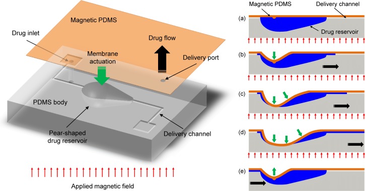
The overall drug delivery device was composed of four main parts: dome-shaped drug reservoir, delivery channels, drug inlet/outlet ports, and magnetic PDMS membrane as depicted in Figure 1. The magnetic membrane composite, which consists of PDMS and iron oxide nanoparticles, is bonded with a PDMS drug reservoir body, the bottom of which is shaped like a pear as depicted in the illustration on the left side of Fig. 1. Under an applied magnetic field, this assembly makes the asymmetric pear-shaped membrane propagate the consecutive touchdown motion from the centroid to the tail of the reservoir that is connected to the outlet and, thus, pushes the drug solution in the reservoir toward the outlet port.13 In other words, the initial touchdown motion of the pear-shaped membrane at the centroid acts as a valve blocking the inlet channel, and the drug solution can be released only through the outlet port by being pushed due to the sequential touchdown motion of the membrane toward the tail of the reservoir (i.e., actuation mode, Figs. 1(a)–1(d)). When the magnetic force is removed, the membrane is then restored to the initial state and inward flow into the reservoir is generated through the inlet channel connected to the head of the pear-shaped reservoir because of the different pressure losses between the inlet and outlet ports (i.e., refilling mode, Fig. 1(e)).13 Therefore, the drug inside the reservoir can be remotely released and controlled without a pair of valves by simply attracting the pear-shaped magnetic membrane using magnetic forces.
FIG. 1.
Schematic illustration of the refillable and magnetically actuated valveless drug delivery device (left side) and principle of operation by the consecutive touchdown motion under a magnetic field (right side, cross-sectional view: (a)–(e)).
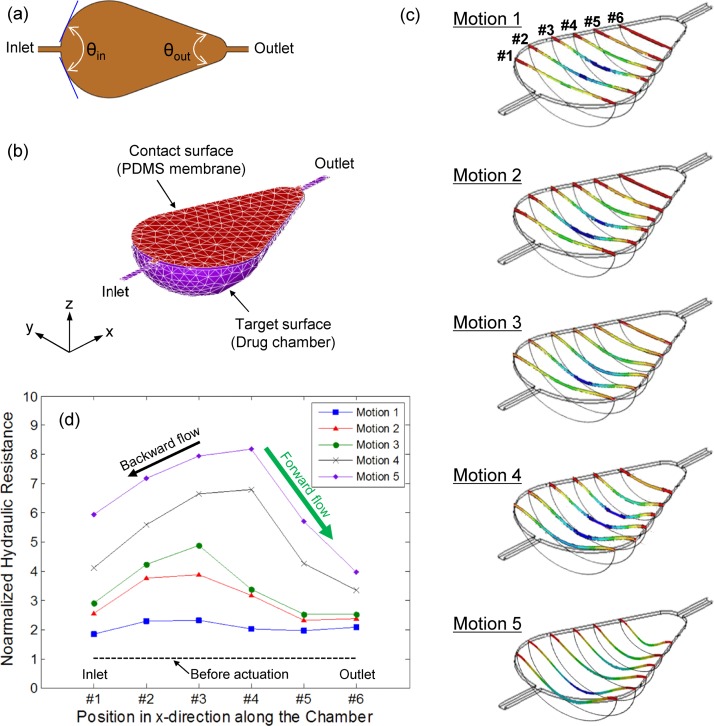
To verify the operating principles of the developed device, a transient mechanical analysis was performed using the finite element method tool, ANSYS Multiphysics 14.0. A sample mesh of the system in the initial state and boundary conditions for nonlinear quasi-static contact models (SOLID186, TARGE170, and CONTA174) are shown in Figures 2(a) and 2(b). As a result of the simulation, the asymmetrical membrane deflection was observed during the contraction motion, as seen in Fig. 2(c). The membrane collapse was initiated from the centroid of the pear-shaped membrane and propagated toward the outlet channel. To estimate the flow direction during the contraction motion, the component of the steady-state Navier-Stokes equation and the volumetric flow rate () definition for the arbitrary cross-sectional channel flow were considered as follows:14
| (1) |
| (2) |
where , , , , and were the pressure drop, dynamic viscosity, channel length, velocity in x-direction, and cross section in plane, respectively. Using the relationship between pressure drop and volumetric flow rate, the corresponding hydrodynamic resistance () was calculated as follows:
| (3) |
where and were the perimeter and area of cross-sectional plane, respectively. Since the flow is typically subject to a no-slip condition along , the hydraulic resistance depends greatly on the perimeter as well as the cross-sectional area, as seen in Eq. (3).14 Considering the above dependence, hydraulic resistances at six different positions (from #1 to #6 in Fig. 2(c)) in the pear-shaped drug chamber for five motions were characterized by the perimeter and area of each cross-sectional plane and normalized by those obtained at the initial state (i.e., before actuation) for a comparative analysis. Fig. 2(d) shows the change of the normalized hydraulic resistances during the asymmetrical membrane deflection. The overall resistances along the chamber length (x-direction) were increased due to the reduced cross-sectional area for flow path as the contraction motion was progressed. It is also noticeable that the graph shape of the normalized hydraulic resistance is similar to the cross-sectional deflection shape of the membrane (Fig. 1), indicating that the flow resistance relies on the degree of deflection. Because the deflection of the membrane propagates from the centroid to both inlet and outlet channels, the hydraulic resistance near the inlet region was rapidly increased in comparison to resistance near the outlet region. This is because the membrane deflection near the outlet regions was delayed by the pear-shaped geometry, which caused a difference of resistance between inlet and outlet channels. Considering that the liquid tends to flow in the direction of least resistance, the drug solution near the centroid in the chamber where the hydraulic resistance has a maximum value flows unavoidably in both inlet (i.e., black arrow in Fig. 2(d)) and outlet (i.e., green arrow in Fig. 2(d)) directions. However, because the resistance near the outlet region was much smaller than that near the inlet region, a greater volume of fluid was pumped in the outlet direction. In other words, even though there was backward flow in the inlet direction, the difference in hydraulic resistance resulting from the asymmetrical membrane deflection induced the net flow in the outlet direction during the contraction motion.
FIG. 2.
(a) Top view of the pear-shaped membrane with different diffuser angles connected to inlet and outlet channels, (b) boundary conditions for computational analysis, (c) transitional change of the asymmetrical membrane deformation under an actuation mode, and (d) change of hydraulic resistance in a pear-shaped chamber for computed five motions.
Conversely, the membrane was relaxed and returned back to the original state during the relaxation motion when the magnetic field was removed. During this relaxation motion, fluids in both outlet and inlet channels flowed back into the chamber because of a sudden drop in pressure inside the chamber. In this case, the head connected to the inlet channel and the tail connected to the outlet channel acted as diffusers with the angle of (143.6°) and (47.1°), respectively (Fig. 2(a)). In general, the pressure loss coefficient () for the internal flow of incompressible fluids is defined as the ratio of pressure drop across the device to the dynamic pressure14,15
| (4) |
and the in the diffuser elements depends on the diffuser angle () and the Reynolds number (Re).16 At low Reynolds numbers (Re < 20), the pressure loss coefficient decreases as the diffuser angle increases,16 while at high Reynolds number (Re > 200), the pressure loss coefficient increases as the diffuser angle increases.15 Considering the diffuser efficiency of a nozzle-diffuser element, causes a pumping action in the inlet direction (i.e., a greater volume of fluid inflows through the outlet channel), while leads to pumping action in the outlet direction (i.e., greater volume of fluid inflows through the inlet channel). When (i.e., no pressure drop in either inlet or outlet direction), fluids return to the original position without pumping action. Based on the experimental data from Rosa and Pinho,16 the at the outlet region ( = 47.1°) was approximately 1.7 times higher than the at the inlet region ( = 143.6°) (i.e., ) for the Re of 15 calculated from the preliminary experiment with a prototype device (volumetric flow rate: 2 μl/s for one actuation). Therefore, the volume of fluid flowing into the chamber from the inlet channel is greater than that from the outlet channel, which prevents the backward flow of discharged drug solution during the relaxation motion and automatically refills the chamber at the same time without external forces.
III. FABRICATION
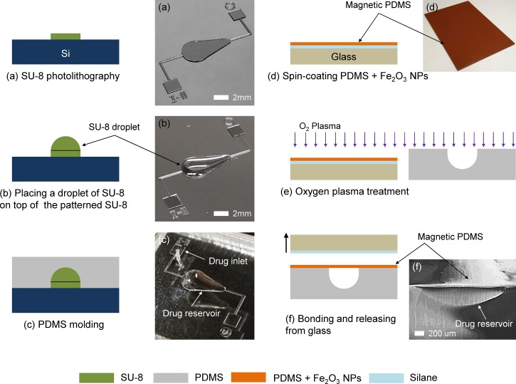
Figure 3 shows the overall fabrication process of the refillable and magnetically actuated valveless drug delivery system. As a standard lithography process, a 100 μm thick negative photoresist—SU-8 2100 (MicroChem, Newton, MA)—was spin-coated at 3000 rpm for 30 s and patterned via contact photolithography (MA6, Karl Suss) with 16.2 mW/cm2 for 15 s onto a clean, 4-in. silicon wafer to create a pear-shaped base mold and drug delivery microchannels (Fig. 3(a)). A droplet of 10 μl SU-8 2005 was then placed on top of the patterned pear-shaped base mold using a pipette to form the dome-shaped mold for a drug reservoir (Fig. 3(b)).17 The capacity of the drug reservoir can be precisely controlled by adjusting the volume of SU-8 droplet. After curing the SU-8 mold under ultraviolet light (ABM Inc., CA) at 9.07 mW/cm2 for 60 min, PDMS (Sylgard 184, Dow Corning, NY) with a mixing ratio of 10:1 (base: curing agent) was poured onto the patterned mold, degassed under vacuum, cured at 90 °C for 2 h, peeled from the mold, and finally punched for the drug inlet port (Fig. 3(c)). To create the magnetic PDMS membrane, iron oxide nanoparticles (<50 nm, Sigma Aldrich) were dissolved in toluene and mixed with PDMS (base: curing agent = 5:1) at mass fraction of 30% w/w particles to PDMS.18 The magnetic membrane then was created by spin-coating at 4000 rpm for 1 min on the glass substrate that was coated with Trichlorosilane (CF3(CF2)5CH2CH2SiCl3, 97%, Sigma Aldrich) as a sacrificial layer (Fig. 3(d)). Because the direction of the applied magnetic field must be perpendicular to the membrane (Fig. 1), a slightly tilted magnet might cause a nonuniform magnetic field and result in a small deformation of the membrane by the weakened attractive force between the membrane and the magnet. To make a large deflection even in the weak magnetic field, a small quantity of PDMS composite mixed with iron nanoparticles was dropped onto the spin-coated membrane. There, it was aligned with the centroid of the pear-shaped geometry in the drug reservoir body and magnetic flux was concentrated to provoke the initiation of the contraction motion from the centroid. Once the magnetic membrane was cured at 100 °C for 2 h, both the pear-shaped drug reservoir body and magnetic PDMS membrane were treated by oxygen plasma (RIE, PETS Inc., CA) with 20 W for 20 s for irreversible bonding (Fig. 3(e)). Finally, the magnetic membrane with an approximate thickness of 38 μm was aligned and bonded with the reservoir body by being released from the glass substrate to form the closed drug reservoir (Fig. 3(f)).
FIG. 3.
Schematic illustration of the fabrication process for the magnetically actuated valveless drug delivery device and corresponding optical/SEM images: (a) SU-8 photolithography, (b) formation of a dome-shaped drug reservoir mold, (c) PDMS casting, (d) spin-coating magnetic PDMS membrane on a glass substrate, (e) oxygen plasma treatment, and (f) PDMS-PDMS bonding.
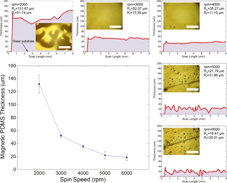
The uniformity of the deposited membrane is one of the key pieces in achieving the asymmetrical deflection under a uniformly applied magnetic force. To determine the optimum thickness of the magnetic PDMS membrane, the uncured PDMS composite was spin-coated on a glass substrate with different spin-coating speeds from 2000 to 6000 rpm. Figure 4 shows the coating thickness with respect to the spin speed and the surface roughness profiles of each deposited composite scanned by a surface profiler (Alpha-Step IQ, KLA-Tencor, CA). At a spin speed of 2000 rpm, the surface had a maximum average thickness (Ra) of 131.87 μm and peak-to-valley height (Rt) of 51.74 μm, resulting in a large waviness because of the aggregation of the PDMS composite, as seen in the inserted optical image. The surface profile then became gradually uniform and the peak-to-valley height was significantly reduced at spin speeds between 3000 and 4000 rpm. The optical images of the top surface view also showed a clean and even surface at these spin speeds. At a speed of more than 5000 rpm, however, the surface profile became unstable, and its roughness was remarkably increased due to irregular voids on the surface that might have caused an imperfectly closed chamber, thus resulting in drug leakage through the membrane. Through this experiment, the magnetic membrane with an approximate thickness between 35 and 40 μm was carefully chosen to form the closed drug reservoir.
FIG. 4.
Thickness of magnetic PDMS membrane with different spin-coating speeds and the surface roughness profile of the membrane with corresponding optical images of the top surface view. Scale bars: 1 mm.
IV. CHARACTERIZATION
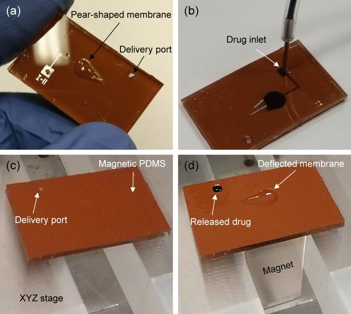
Figure 5(a) shows an actual size and top surface view of the fabricated drug delivery device. The whole device was made of the flexible 1.5 mm thick PDMS layer so it can be directly attached or implanted on the curved surfaces of the body such as the eyeball, knee, or scalp, using a simple surgical operation. Because the lifetime of the battery-less type devices generally relies on the ability to refill the reservoir, the refill function of the developed device was demonstrated with 1% methylene blue (Science Company, CO). As seen in Fig. 5(b), the maximum 10 μl volume of aqueous drug solution could be simply loaded into the dome-shaped drug reservoir through the external syringe tube and inlet port. Thus, the device can be repeatedly used so long as the drug solution is supplied through the external tube. For characterization of the on-demand controlled drug release performance by the developed device, a neodymium permanent magnet 1/2″ 1/2″ 1″ thick (B88X0, K&J Magnetics Inc., PA) magnetized along thickness direction and XYZ stage were used to provide the magnetic field and to change its strength by adjusting the vertical distance of the magnet from the device, respectively. To evaluate the drug release rate under different strengths of magnetic field, the magnetic flux density was measured using a Gaussmeter (Model 410, Lake Shore Cryotronics Inc., OH) as a function of the distance from the magnet. Finally, three devices were tested and all measurements were repeated three times for each device.
FIG. 5.
Experimental images of the fabricated drug delivery device: (a) top surface view, (b) manually refilled reservoir with drug solution (1% methylene blue), (c) device off-mode without magnetic field, and (d) device on-mode under magnetic field of 400 mT.
V. RESULTS AND DISCUSSION
Figure 5(c) shows the backside of the fabricated device placed on the XYZ stage without the magnet underneath. It was clearly found that the drug solution was unable to be released at all through the delivery outlet port because the membrane was undeflected by the magnetic force. However, once the magnetic field was applied for an actuation mode, the drug solution was discharged after 1 s through the outlet port, while the asymmetrically deflected membrane prevented backward flow to the inlet port, as shown in Fig. 5(d). This one-way fluid transport could be achieved by the sequential touchdown motion of the tailored asymmetrical pear-shaped membrane under a magnetic field, inducing the difference of hydraulic resistances and pressure losses between inlet and outlet ports, whereas the drug fluid is apparently released through both inlet and outlet ports if the device is trigged by symmetrically shaped membranes such as a circle or a rectangle ( in this case). Thus, the developed device could deliver the drug solution directly within a short period with significantly reduced fabrication cost and complexity, which are the main drawbacks of valve-type drug delivery systems.
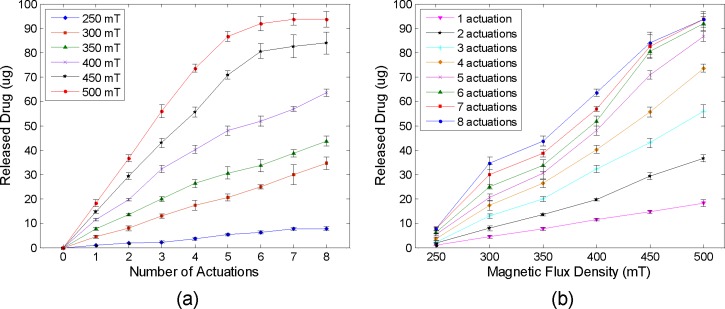
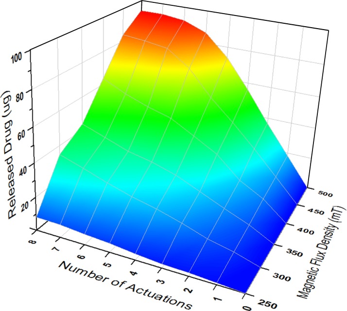
To quantitatively evaluate the amount of released drug as a function of the number of accumulated actuations and magnetic fields, the released drug solution in each actuation under different magnetic strengths from 250 to 500 mT were collected by a pipette and the weights of solution were measured rapidly using an analytical balance (Pinnacle PI-214, 0.1 mg readability, Denver Instrument, CO) before the solution started to evaporate. Considering the drug amount in the 1% methylene blue solution (10 mg/ml) and the density (1 g/ml), each amount of released drug in the unit of micrograms (μg) was calculated by multiplying by 10 the measured weights of the solution in the unit of milligrams (mg). Figures 6(a) and 6(b) show the measured drug amount in the aqueous solution discharged by the consecutive touchdown motion with respect to the number of accumulated actuations and different magnetic flux densities, respectively. The result showed that the amount of discharged drug was directly proportional to the number of accumulated actuations up to 350 mT as seen in Fig. 6(a). An average release rate of 4.29 ± 0.71 μg per actuation was achieved under the magnetic field of 300 mT. The released amount, however, was saturated as average peak values of 84 and 93.7 μg under 450 and 500 mT after 8 actuations, respectively. Considering the 100 μg drug content in the dome-shaped reservoir, the small quantity of drug solution remained along the edge of the chamber because the applied magnetic field was not strong enough to completely pull down the magnetic membrane and, thus, was unable to achieve perfect contact between the membrane and side wall of the reservoir. Hence, further parametric investigations for various sizes of pear-shaped chambers and required strength of magnetic fields will be needed to increase the on-demand release rate. One possible design to make a perfect contact between the membrane and side wall of the reservoir is to replace iron oxide nanoparticles with a thin disc-shaped magnet in the PDMS membrane to increase the attractive force between the membrane and the magnet. Because the membrane will be deflected slightly even before activation due to the weight of the enclosed thin magnet, thicker PDMS coating and the alignment between the centroid of the chamber and center of the enclosed magnet are necessary for this design. It was also found that the amount of discharged drug was proportionally increased as the magnetic field was increased as seen in Fig. 6(b). For a single expulsion of drug solution, a consistent release amount of 3.47 ± 0.45 μg was increased per every 50 mT increment from 250 (∼1 μg) to 500 mT (∼18.3 μg). Figure 7 shows the three-dimensional plot of the discharged drug amount with the combination of the number of accumulated actuations and the strength of the magnetic field. This map can be effectively used to determine the number of actuations and desired strength of the magnetic field for the specific dosage that must be delivered to a target site. Therefore, the developed magnetically actuated drug delivery device with the pear-shaped magnetic membrane provided the on-demand controlled and reproducible release with easier operation, cost-effective fabrication, and implantable function.
FIG. 6.
Released drug amount with respect to the (a) number of accumulated actuations and (b) different magnetic flux densities.
FIG. 7.
Three-dimensional plot of the released drug amount with respect to the number of accumulated actuations and different magnetic flux densities.
VI. CONCLUSIONS
In summary, a directly refillable and remotely controllable drug delivery device was developed for on-demand controlled, consistent, and reproducible drug release to treat localized diseases without the assistance of specialized stimulus-responsive nanomaterials or microfluidic components. The device featuring a pear-shaped membrane was demonstrated with a simple fabrication process by soft lithography, and the PDMS magnetic membrane was successfully fabricated with iron oxide nanoparticles. To characterize on-demand controlled drug release, the fabricated device was tested with a commercially available neodymium magnet in response to the various magnetic strengths and the number of accumulated actuations. The drug solution was rapidly released through the delivery outlet port by a sequential touchdown motion and deflection of the asymmetrical pear-shaped membrane, resulting in one-way fluid transport through microchannels without a microfluidic valve. This all-PDMS device allowed a successful, efficient, and consistent drug release rate in each actuation within a short time compared to conventional drug delivery devices that require complicated fabrication steps and expensive specialized materials or equipment such as an electric platform and on-chip battery. For a real in vivo drug delivery, the developed device can be directly attached or implanted on the curved surfaces of the body—including the eyeball, knee, or scalp—because of the flexibility of the all-PDMS device. Once it is implanted underneath the skin using a simple surgical operation, various magnets with different strengths can be directly applied on the skin where the device is implanted, and the distance between the skin and device remains fixed. Therefore, a patient can control the drug dose by applying a different magnet prescribed by a doctor to discharge the required dosage and treat the localized diseases. This approach could be more practical than controlling the distance between the device and external magnet to adjust the strength of the magnetic force, and eliminate operating difficulties. This study indicates the potential of the MEMS-based magnetically actuated valveless drug delivery system to address clinical requirements for treatment of localized diseases by providing a cost-effective and simple operation.
ACKNOWLEDGMENTS
This work was supported by the KAUST Global Collaborative Research grant under the Academic Excellence Alliance program. The authors also thank the UC Berkeley Marvell Nanolab and Biomolecular Nanotechnology Center where all devices were fabricated.
References
- 1.Sershen S. and West J., Adv. Drug Delivery Rev. 54, 1225–1235 (2002). 10.1016/S0169-409X(02)00090-X [DOI] [PubMed] [Google Scholar]
- 2.Tsai N.-C. and Sue C.-T., Sens. Actuators, A 134, 555–564 (2007). 10.1016/j.sna.2006.06.014 [DOI] [Google Scholar]
- 3.Stevenson C. L., J. T. Santini, Jr. , and Langer R., Adv. Drug Delivery Rev. 64, 1590–1602 (2012). 10.1016/j.addr.2012.02.005 [DOI] [PMC free article] [PubMed] [Google Scholar]
- 4.Okano T., Bae Y. H., Jacobs H., and Kim S. W., J. Controlled Release 11, 255–265 (1990). 10.1016/0168-3659(90)90138-J [DOI] [Google Scholar]
- 5.Kwon I. C., Bae Y. H., and Kim S. W., Nature 354, 291–293 (1991). 10.1038/354291a0 [DOI] [PubMed] [Google Scholar]
- 6.Hoare T., Santamaria J., Goya G. F., Irusta S., Lin D., Lau S., Padera R., Langer R., and Kohane D. S., Nano Lett. 9(10), 3651–3657 (2009). 10.1021/nl9018935 [DOI] [PMC free article] [PubMed] [Google Scholar]
- 7.Mathiowitz E. and Cohen M. D., J. Membr. Sci. 40, 1–26 (1989). 10.1016/S0376-7388(00)80909-6 [DOI] [Google Scholar]
- 8.Kost J., Leong K., and Langer R., Proc. Natl. Acad. Sci. USA 86, 7663–7666 (1989). 10.1073/pnas.86.20.7663 [DOI] [PMC free article] [PubMed] [Google Scholar]
- 9.Liu T.-Y., Hu S.-H., Liu D.-M., Chen S.-Y., and Chen I.-W., Nano Today 4, 52–65 (2009). 10.1016/j.nantod.2008.10.011 [DOI] [Google Scholar]
- 10.Son S. J., Reichel J., He B., Schuchman M., and Lee S. B., J. Am. Chem. Soc. 127, 7316–7317 (2005). 10.1021/ja0517365 [DOI] [PubMed] [Google Scholar]
- 11.Pirmoradi F. N., Jackson J. K., Burt H. M., and Chiao M., Lab Chip 11, 2744–2752 (2011). 10.1039/c1lc20134d [DOI] [PubMed] [Google Scholar]
- 12.Lemoff A. V. and Lee A. P., Sens. Actuators, B 63, 178–185 (2000). 10.1016/S0925-4005(00)00355-5 [DOI] [Google Scholar]
- 13.So H., Pisano A. P., and Seo Y. H., Lab Chip 14, 2240–2248 (2014). 10.1039/c3lc51298c [DOI] [PubMed] [Google Scholar]
- 14.Bruus H., Theoretical Microfluidics ( Oxford University Press, 2008). [Google Scholar]
- 15.Singhal V., Garimella S. V., and Murthy J. Y., Sens. Actuators, A 113, 226–235 (2004). 10.1016/j.sna.2004.03.002 [DOI] [Google Scholar]
- 16.Rosa S. and Pinho F. T., Int. J. Heat Fluid Flow 27, 319–328 (2006). 10.1016/j.ijheatfluidflow.2005.09.003 [DOI] [Google Scholar]
- 17.Su Y.-C. and Lin L., J. Microelectromech. Syst. 13, 75–82 (2004). 10.1109/JMEMS.2003.823215 [DOI] [Google Scholar]
- 18.Pirmoradi F. N., Cheng L., and Chiao M., J. Micromech. Microeng. 20, 015032 (2010). 10.1088/0960-1317/20/1/015032 [DOI] [Google Scholar]


