Abstract
Parallel excitation requires fast and accurate B1 map estimation. Bloch-Siegert (BS) B1 mapping is very fast and accurate over a large dynamic range. When applied to multi-coil systems, however, this phase-based method may produce low SNR estimates in low magnitude regions due to localized excitation patterns of parallel excitation systems. Also, the imaging time increases with the number of coils. In this work, we first propose to modify the standard BS B1 mapping sequence so that it avoids the scans required by previous B1 phase estimation methods. A regularized method is then proposed to jointly estimate the magnitude and phase of multi-coil B1 maps from BS B1 mapping data, improving estimation quality by using the prior knowledge of the smoothness of B1 magnitude and phase. Lastly, we use Cramer-Rao Lower Bound analysis to optimize the coil combinations, to improve the quality of the raw data for B1 estimation. The proposed methods are demonstrated by simulations and phantom experiments.
Index Terms: Magnetic Resonance Imaging (MRI), B1 mapping, parallel excitation, Bloch-Sieget B1 mapping, regularization, phase estimation, Cramer-Rao Lower Bound
I. Introduction
For MRI with parallel excitation (PEX), it is critical to rapidly and accurately estimate the magnitude and relative phase of the multi-channel B1 field, also known as mapping. Numerous methods have been proposed to map B1 magnitude, such as double-angle method [1], actual flip angle imaging (AFI) [2] and Bloch-Siegert (BS) B1 mapping [3]. PEX pulse design also needs the relative phase maps, i.e., the phase of one coil relative to that of all the other coils, which is typically mapped by successively exciting the same object with each coil and receiving the signal by one common coil or one common set of coils.
The approach described in this paper uses the BS B1 mapping method which applies an off-resonance RF pulse between the excitation pulse and the readout gradients [3]. This off-resonance Bloch-Siegert (BS) pulse induces phase shifts that are proportional to |B1|2. The BS method is popular because it is fast and relatively accurate over a wide dynamic range and it is insensitive to T1, chemical shift, B0 field inhomogeneity and magnetization transfer effects [3]. Its speed and wide dynamic range are especially beneficial for PEX systems where B1 mapping is generally more time-consuming and has wider dynamic ranges than single channel systems. However, a disadvantage of this phase-based method is that the B1 field estimation in low magnitude regions may suffer from low signal-to-noise ratio (SNR), due to insufficient excitation or low spin density. In particular, the problem of insufficient excitation is severe in PEX B1 mapping because of the localized B1 sensitivities of each coil. Furthermore, conventional estimation of B1 phase needs another set of scans, which might be information redundant.
BS B1 mapping for PEX has been improved in [4] by using combinations of multiple coils for imaging excitation. However, regions of low spin density and/or insufficient excitation may still be problematic, and estimation of B1 phase still needs additional scans. Simply smoothing the noisy images with low-pass filters may propagate errors from the corrupted regions into neighboring regions. Therefore, we propose a modified BS B1 mapping procedure that estimates both the magnitude and phase maps, avoiding the additional phase mapping scans required by conventional methods; then a regularized estimation method is proposed to jointly estimate the magnitude and relative phase of multi-coil B1 maps from this BS B1 mapping data. By utilizing the prior knowledge that B1 maps are smooth, regularization can improve B1 map estimation in low magnitude regions.
Many B1 mapping methods, e.g., [4] [5] [6], use linear combinations of PEX channels to narrow the dynamic range of the effective B1 field for better SNR, where typically all-but-one strategies are applied. However, these strategies are likely to be suboptimal in practice: the power levels of different channels in the object could be uneven due to non-isocenter positioning, which may cause nonuniform B1 magnitude in the composite fields; the relative phase between channels could be far from what is assumed in those strategies, which may produce dark holes in the composite fields. Malik et al. proposed a method to optimize coil combinations for PEX B1 mapping [7], but it optimized only over a single complex parameter of the combination matrix over a limited range empirically. That work evaluated the results according to two criteria: the dynamic range of the composite B1 maps and the condition number of the combination matrix, which sometimes are hard to balance and also may not indicate the estimation quality. In this paper, we propose to optimize linear coil combinations in [8] based on Cramer-Rao Lower Bound (CRLB) analysis [9]. The proposed method is general enough to optimize the combinations over all the elements of the coil combination matrix, providing the most flexibility for optimization. We evaluated the combinations directly based on the variance of the complex B1 field estimates instead of indirect factors like dynamic ranges and condition numbers. The proposed approach minimizes the estimation variance of the pixel that has the maximal estimation variance, reducing the occurrence of focal noise amplification. Simulated Annealing (SA) [10] is used for this highly nonlinear optimization problem.
This paper is organized by starting with the signal model of images acquired by the proposed BS B1 mapping sequence and then introducing the regularized estimation. We next demonstrate the proposed regularized method with simulation studies and phantom experiments at 3T. Section III considers optimization of the coil combinations using CRLB analysis, and then demonstrates the proposed methods by comparisons with the conventional all-but-one method and the method in [7] using simulation studies. Note that the regularized B1 estimation algorithm in Section II and the coil combination optimization approach in Section III are relatively independent; these two methods may be combined, but neither of them requires the knowledge or results of the other.
II. Regularized BS B1 Estimation
A. Linear Combinations of Coils in B1 Mapping
Instead of mapping one coil at a time, we estimate the multi-channel B1 field by acquiring standard BS B1 mapping data with multiple coils turned on at each time [4]. Each composite complex B1 field, C̃n(r), is a linear combination of the complex B1 maps, Cm(r), of the individual coils:
| (1) |
where n = 1, 2, …, N, N is the number of channels available, r denotes the spatial locations, and αn,m is the user-defined complex scalar weighting for the mth individual coil in the nth scan. A convenient choice for αn,m is the so-called all-but-one or leave-one-coil-out strategy, where α(n, n) = 0 or −1 and αn,m = 1 when m ≠ n [5] [11]. Both the composite complex B1 maps and the individual complex B1 maps can be expressed in terms of their magnitudes and phases:
| (2) |
B. The Signal Model
Standard BS B1 mapping applies the BS pulse after the regular excitation pulse [3]. This method typically needs 2 scans for each coil to measure B1 magnitude, thus 2N scans are needed for an N-channel PEX system. To estimate both B1 magnitude and relative phase by the standard BS B1 mapping without additional scans for phase, we propose to use the same coil combinations for the BS pulse and the corresponding excitation pulse. The signal models for the noiseless BS data (reconstructed images) of the N pairs of scans, i.e., and , are described as follows:
| (3) |
where n = 1, 2, …, N, and as described in (2), B̃n(r) and ϕ̃n(r) denote the magnitude and phase of the composite B1 fields respectively; the superscripts ± denote the scan that has the BS pulse with ±ωRF off-resonance frequency, μ is the ratio between the actual flip angle and B̃n(r), is the magnetization related to spin density, T1, T2, TR, TE, flip angle, receive sensitivity, magnetization transfer (MT) effect, etc., ϕb(r) is the corresponding unknown background phase, and is the BS pulse constant that incorporates the B0 field map [3]:
| (4) |
where Bnormalized(t) is the normalized shape of the BS pulse. Due to the asymmetric MT effect [12], is slightly different from . Moreover, we model additive independent and identically distributed (i.i.d.) complex Gaussian noise, i.e., , to the signal, and simplify (3) by changing variables:
| (5) |
where are the noisy images from the nth pair of scans, , and . The simplest way to estimate B1 magnitude and phase from this set of data is to first obtain B̃n(r) using the standard BS B1 mapping estimator [3], and then, given B̃n(r), the relative B1 phase, , can be derived by maximum likelihood estimator of (5) or simply taking:
| (6) |
where is not needed. We propose to set the coil combination of each excitation pulse the same as its corresponding BS pulse, so that B̃n(r) and correspond to the same composite B1 map, hence the individual B1 magnitude and phase, i.e., Bn(r) and , can be derived by (9) below. This is how the modified BS sequence can avoid the additional scans for B1 phase. For regularized estimation, is a set of nuisance parameters that we must jointly estimate, but they are fortunately linear terms that can be easily estimated.
C. Regularized Estimation of B1 Magnitude and Phase
Regularization enforces prior knowledge to improve estimation. It is reasonable to assume that the complex B1 fields of the individual coils, i.e., Bm(r)eiϕm(r), are spatially smooth. As shown in the signal models (5), the B1 magnitude and phase are separate, and the fields of the individual coils are superimposed with each other due to the coil combinations. Thus, it is easier to estimate magnitude and phase of the composite B1 fields separately [13], even though the regularization is for the complex fields of the individual coils. Grouping all discretized spatially varying maps into column vectors (shown in bold fonts), we proposed regularized maximum-likelihood estimation by minimizing the following cost function:
| (7) |
where β is the scalar regularization parameter, M is the concatenation of the image magnitude vectors of all channels, B̃ and ϕ̃ denote the concatenation of all the composite B1 magnitudes B̃n and all the composite B1 phases , respectively, “⊙” denotes element-by-element multiplication between vectors, denotes the vector that contains the squares of the corresponding elements of B̃n, Bn and denote the individual B1 magnitudes and phases respectively, and C is a multi-dimensional finite differencing matrix used to penalize roughness. For simplicity of the expression in (7), we do not show the inherent relation between and in the regularization term, which is shown in (9). Note that the units of the data fit term may be abitrarily different for different scans, and the regularization term can also have different units. To make it easier to choose a value of β that works for different scans, we normalize the data in (7) so that has unit norm, and we always use units μT for Bn. This ensures that β always has consistent units (1/μT2).
We iteratively minimize the cost function (7) by cyclically updating B̃, ϕ̃ and M:
| (8) |
where and M̂ denote the estimates of B̃, ϕ̃, M respectively, and Np is the number of pixels of each channel. We update M, which is a real unknown, by simply taking the real least-squares solution of (7) in each iteration. The cost function is non-quadratic in B̃ and ϕ̃, so we use conjugate gradients with backtracking line search algorithms (BCG-LS) [13] [14] to update B̃ and ϕ̃ respectively. The standard approach [3] produces a good initial guess for B̃, and then we compute the initial guess of ϕ̃ using (6). The stopping criterion for this optimization algorithm is to check whether the change of the cost function Φ between two consecutive iterations is smaller than a certain value. Once B̃ and ϕ̃ are estimated, magnitude and relative phase maps of the original coils, B and ϕ, are derived easily using the following relation:
| (9) |
where , which does not change the relative phase maps, and A is the coil combination matrix:
| (10) |
D. Simulation Study
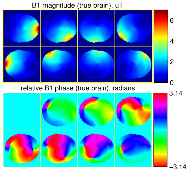
We performed a simulation study to demonstrate the proposed BS B1 mapping sequence and the corresponding regularized B1 estimation method. First, a finite-difference time-domain (FDTD) simulation generated 2D magnetic fields of an eight-channel parallel excitation array for brain imaging at 3T, which were used as the true B1 maps in the simulations (shown in Fig. 1). We used a set of brain tissue parameter maps, e.g., T1 map, T2 map and spin densities, from BrainWeb database [15]–[19] as the true values for generating images produced by the BS sequence. The image magnitude was generated based on the signal equation of spoiled gradient echo (SPGR) sequence that is shown below in (17) with flip angle = 200, TR = 200 ms, TE = 10 ms. We then used Bloch equation simulations to generate the image phase based on ±4 kHz off-resonance Fermi BS pulses (KBS = 76.9rad/G2) and a realistic B0 field map acquired from a head scan on a 3T GE scanner (ranging from −86 Hz to 25 Hz). We combined the B1 fields with the all-but-one strategy with α1,1 = −1, α1,2 = … = α1,N = 1. Adding i.i.d. complex Gaussian noise to the noiseless images, we simulated the raw data in image domain acquired by SPGR-based BS B1 mapping sequence with the proposed modifications, and the SNR of the raw data was around 34 dB. The SNR is defined in image domain as:
| (11) |
where St and S denote the noise-free and noisy images respectively. Each method was applied to datasets for 20 instances of random noise. The matrix size of each 2D image is 64 × 64, and field of view is 24 cm × 24 cm. Moreover, estimator (8) uses a mask in the image domain to eliminate space outside the object. This mask can be obtained from the images acquired for the B0 mapping or the BS images.
Fig. 1.
B1 maps of a head, used as the ground truth in simulation study.
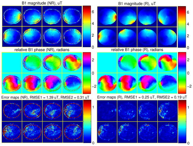
Using these simulated raw coil images, we compared the proposed regularized B1 estimation method with standard non-regularized methods for B1 magnitude and phase. For the proposed method, we manually selected the regularization parameter to be β = 0.15. The matrix C in (7) was a second-order 2D finite differencing matrix. Fig. 2 shows the reconstructed B1 magnitude and phase maps produced by the standard non-regularized method and the proposed regularized method for one instance of random noise. Fig. 2 also shows the error maps of the complex B1 maps, i.e., |B̂ ⊙ eiϕ̂ − B ⊙ eiϕ| for each method, where each pixel value is the average error magnitude over the 20 instances of random noise. All the images in Fig. 2 are displayed with the mask used in the optimization. Based on these images, we also computed the root mean square error (RMSE) for each complex B1 map:
| (12) |
Fig. 2.
The estimated B1 magnitude (top row), phase (middle row) maps and the error (bottom row) maps by the non-regularized (NR) method (left) and the regularized (R) method (right) using conventional all-but-one coil combination scans, in simulation study.
We calculated the RMSE values both with the mask used in the optimization and a more accurate mask obtained from the true brain image respectively, and they are denoted as RMSE1 and RMSE2 respectively. The latter mask excludes signal-free regions within the former mask, which is the skull region, because the skull region may dominate RMSE1 in some methods but it is less important for pulse design. Fig. 2 shows those RMSEs (averaged over the 20 instances of random noise) in the figure titles of the error maps. Compared to the non-regularized method, the proposed regularized B1 estimation produced less noisy B1 maps that have significantly smaller errors.
E. Phantom Experiments
We performed phantom experiments to demonstrate the proposed regularized BS B1 map estimation on a 3T GE scanner (GE Healthcare, Milwaukee, WI, USA) equipped with an 8-channel custom parallel transmit/receive system [20] [21]. We used a spherical phantom filled with distilled water. Due to a failure in one RF amplifier, only seven of the transmit channels were used; the eighth has zero input throughout the experiment. All the data were acquired with a SPGR sequence having a 2D spin-warp readout. We applied a 20 ms Fermi BS pulse with ±4 kHz off-resonance frequencies. Other imaging parameters were: TE = 23 ms, TR = 200 ms, FOV = 24 × 24 cm, 64 × 64 reconstruction matrix size, and axial slice imaging. The eight-channel parallel imaging data produces one image per channel using FFT reconstruction. Each set of eight-channel images were then combined into single-channel images by a weighted summation across channels. Each channel has one scalar complex weight. Based on a set of receive sensitivity maps acquired off-line, the weights were adjusted to produce a homogeneous receive sensitivity, which is analogous to RF shimming for a homogeneous transmit sensitivity [22].
We first acquired a B0 map (ranges from −80 to 8 Hz) using two 2D SPGR scans with an echo time difference 2.5 ms. A total of 14 proposed BS B1 mapping scans were acquired for 7-channel B1 estimation, where we applied the all-but-one coil combination with α1,1 = 0, α1,2 = … = α1,N = 1. The reconstructed raw images were then put into the standard non-regularized BS estimator and the proposed regularized BS estimator (8). For the proposed method, we manually selected the regularization parameter to be β = 4, and the matrix C in (7) was second-order 2D finite differencing matrix. A mask obtained from the SPGR image used for B0 mapping was applied to the estimation. The whole reconstruction took less than a minute on a computer with Intel Core i5 CPU @ 2.5 GHz, 4 GB RAM and Matlab 8.1. Fig. 3 shows the estimated B1 magnitude and phase maps, where the mask used for the estimation is applied to all the images. The proposed regularized estimation improves the quality of both the magnitude and phase maps. However, there are still several rough spots in the magnitude maps that were corrupted by the low signal intensity regions so much that they were not fully smoothed by the regularized algorithm. This is the main motivation for us to propose coil combination optimization, to obtain better raw data for B1 estimation, as discussed in the next section.
Fig. 3.
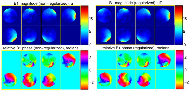
The estimated B1 magnitude (top) and phase (bottom) maps by the non-regularized method (left) and the regularized method (right), in phantom study.
III. Coil Combination Optimization
A. Approximate Signal Model
The coil combination matrix A in (10) is conventionally chosen by an all-but-one strategy, but this approach is unlikely to be optimal in practice. Therefore, we propose a method to optimize the matrix A to improve the quality of the raw data for estimating the magnitude and phase of B1 field in PEX. We use the CRLB to derive a lower bound on the variance of the complex B1 field estimates in terms of the coil combination matrix A and then find the A that minimizes the worst-case noise-to-signal ratio (NSR).
To simplify the CRLB analysis, we make some approximations for (5): asymmetric MT effect is ignored so that
, and the off-resonance effects in
are ignored so that
, which is a scalar constant. Assuming the real and imaginary parts of the i.i.d. Gaussian noise are uncorrelated and distributed as
 (0, σ2) where σ2 is the variance, then the approximate distributions of the signals for each pixel are expressed as follows:
| (13) |
where the subscripts n, indices r, primes and tildes in (5) are omitted for simplicity, subscripts r/i denote the real/imaginary parts.
B. Cramel-Rao Lower Bound Analysis
The CRLB is a lower bound on the covariance of any unbiased estimator under certain regularity conditions. Although the nonlinear reqularized estimator (8) is biased in general, even when β = 0, it is still desirable to minimize the CRLB to pursue improved data quality.
Equation (13) can be vectorized as follows:
| (14) |
where , μ = [M cos(KB2 + ϕ), M sin(KB2 + ϕ), M cos(−KB2 + ϕ), M sin(−KB2 + ϕ)]T, θ = [B, ϕ]T. The Appendix verifies that this problem satisfies the regularity condition for the CRLB theorem. Using a Taylor expansion and assuming the scans have independent noise, the Appendix derives the lower bound of the variances of the complex B1 estimates of the N channels in location r:
| (15) |
where n = 1, …, N, diag{z} denotes the diagonal matrix with vector z its diagonal entries, and we have put back the subscripts n, indices r, primes and tildes in (5) except that we move the indices r to the subscripts and make A be the argument, as A is the main unknown of the coil combination optimization problem.
C. Optimize Linear Combinations of Array Elements
We optimize the SNR of the B1 estimates by minimizing the lower bound of NSR, defined as the ratio between and Bn(r). Since (15) is only for one single pixel, a scalar that evaluates the noise performance of the whole 2D or 3D B1 field of the N coils must be chosen for optimizing over the coil combination matrix A. To suppress the focal noise amplifications that are common in PEX B1 mapping, we apply a min-max optimization strategy by minimizing the maximal Vn,r(A) over all spatial locations and channels to optimize the worst noise performance of the whole estimation. A practical issue is that PEX systems have amplitude limits that bound the maximum magnitude of the elements of A. Therefore, the final expression of this optimization problem is:
| (16) |
subject to
where λ is the amplitude limit of the PEX system. This method optimizes the noise performance over all the elements αm,n of A, which is much more flexible than the method in [7].
The cost function in (16) is highly nonlinear and nonconvex in terms of A, so it would be very hard to find the global minimum. In practice, however, it should suffice to keep the noise level below a certain reasonable value rather than to exhaustively search for the global minimizer. Since A is relatively a small matrix, we found that the Simulated Annealing (SA) method [10] in Matlab’s Optimization Toolbox can efficiently find a reasonably good local minimum.
The CRLB expression (15) depends not only on the coil combination matrix A, but also on other parameter maps that are not known, namely Mn,r(A) and B̃n,r(A). The composite maps B̃n,r(A) can be described as:
| (17) |
The maps Mn,r(A) depend on other parameters that are unknown, such as T1, T2 and spin density, and can be modeled mathematically according to the specific imaging sequence. In this paper, we focus on the SPGR based BS sequence, where Mn,r(A) can expressed as follows [23]:
| (18) |
where is the receive coil sensitivity map, ρ(r) is the spin density map, T1(r) and T2(r) are the T1 and T2 maps respectively. Instead of attempting to determine these maps, which would be impractical, we use uniform maps with nominal T1, T2, and ρ values for optimizing A. For , we either use uniform values when signal is received by a single coil in a non-high field scanner (≤3T), or acquire an off-line phantom data for a coarse estimation of . For the transmit B1 magnitude, Bm(r), we use a set of B1 maps estimated by a phantom off-line. For the transmit B1 phase, ϕm(r), we either use off-line phantom estimates or fast on-line low resolution in-vivo B1 phase maps.
For our experiments, we focus on an eight-channel PEX head array that has 8-fold rotational symmetry, so although the proposed method can optimize over all the elements of A, it is natural to restrict the 8×8 matrix A to be circulant, saving computation time by reducing the number of unknowns to 8. This approach also seems to be more robust to local minima compared to optimizing all elements of A.
D. Simulation Study
In this study, we used the same reference B1 maps generated by FDTD simulation in the section II-D (shown in Fig. 1). We also used the same set of brain tissue parameter maps used in Section II-D as the true values for generating images produced by the BS sequence. The image magnitude was generated based on the signal equation of SPGR sequence (17) with TR = 200 ms, TE = 10 ms. The BS induced phase was simulated based on 8 ms ±4 kHz off-resonance Fermi BS pulses (KBS = 76.9 rad/G2) and a realistic B0 field map acquired from a brain on a 3T GE scanner (ranging from −86 Hz to 25 Hz). Furthermore, the map was acquired from a real single-channel body receive coil of the 3T GE scanner. By adding i.i.d. complex Gaussian noise to the noiseless images generated based on (3), (17) and (18), we simulated the raw data in image domain acquired by SPGR-based BS B1 mapping sequence. The matrix size of these 2D images is 64 × 64. Note that the coil combination matrix A has to be optimized before simulating the raw data. In the data simulation, the standard deviation of the Gaussian noise stayed the same and the SNR of raw image data ranged from 23 dB to 26 dB depending on the specific coil combinations.
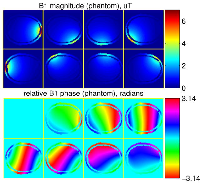
We used approximated parameters for the coil optimization step (16). T2 and spin density were uniform maps with nominal values, as the absolute values of them do not affect the optimization of (16); T1 maps were set to be the maximal value (2.6 s) of brain tissue. Since the true receive coil sensitivity map, which was acquired from a single-channel at 3T, is relatively uniform, we used a uniform map for the optimization. Furthermore, we performed another FDTD simulation for a uniform phantom using the same coil con-figurations as we used for the brain simulation. The relative permittivity and conductivity of the phantom were set to be the corresponding average values of brain tissue, that is, 42.3 and 0.489 S/m respectively. The phantom had uniform spin density over the same spatial regions occupied by the brain in the previous FDTD simulation, and we cropped the phantom B1 maps to match the brain shape for the optimization (shown in Fig. 4). For the B1 phase specifically, in addition to using the phantom B1 phase, which will be called “method 1”, we also simulated a set of on-line low resolution (32 × 32 matrix) fast scans of the brain using one transmit coil at a time to obtain the relative B1 phase, which will be called “method 2”. Moreover, for comparison purposes, we also simulated the case where we optimized the coil combinations based on the true B1 maps as well as true B1−, T1, T2 and spin density maps, called “oracle method”. Table I summarizes the proposed methods. Circulant structure was assumed for the matrix A, and the optimization algorithm was initialized with the all-but-one combination. The threshold λ in (16) was set such that the RF power does not exceed a fixed peak nominal power. Furthermore, a fast low resolution prescan of the subject was simulated for defining a mask for the optimization. For illustration and analysis, a more accurate mask extracted from the true brain image was applied to all the images shown and computed the statistics for this simulation.
Fig. 4.
B1 maps of the phantom (masked by the brain shape), used for optimizing the coil combinations.
TABLE I.
Summary of the Methods in the Coil Combination Simulation
| B1 magnitude estimation | B1 phase estimation | B1−, T1, T2, spin density | |
|---|---|---|---|
| “method 1” | Phantom (off-line) | Phantom (off-line) | Uniform maps |
| “method 2” | Phantom (off-line) | Low-res in-vivo (online) | Uniform maps |
| “oracle method” | True B1 magnitude | True B1 phase | True maps |
For comparison, we also simulated the results of the all-but-one combination with α1,1 = −1, α1,2 = … = α1,N = 1 and the method proposed by Malik et al. [7]. For Malik’s method, we investigated the diagonal entry αeiβ within the range suggested in [7], i.e., −11 < α < 11 and −π/2 < β < π/2, while keeping the off-diagonal entries to be 1. The B1 mapping simulations for this method were also based on the SPGR-based BS B1 mapping mentioned above. The optimal choice of αeiβ was chosen by minimizing RMSE between the reconstructed complex B1 maps and the corresponding truth.
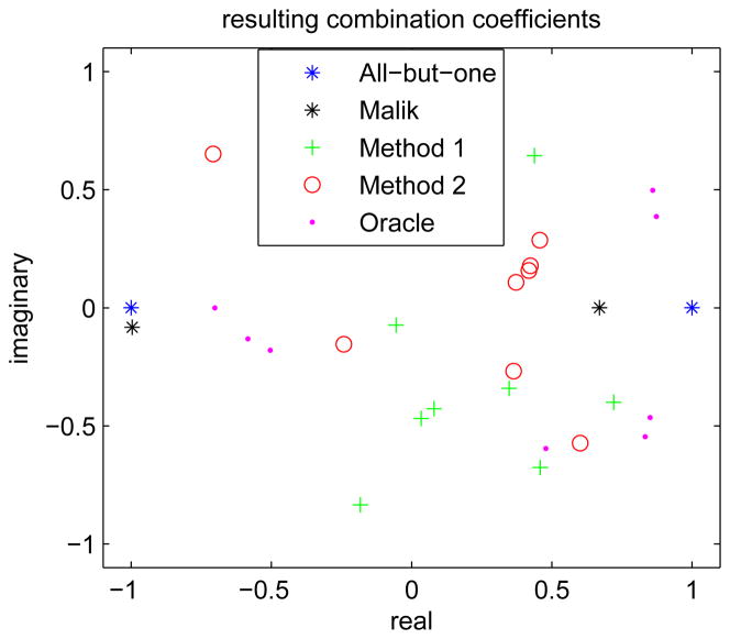
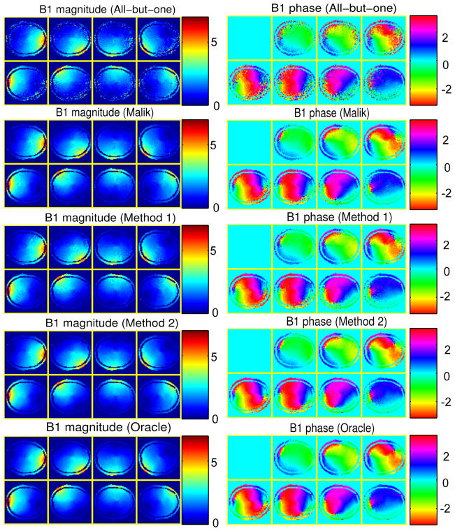
Fig. 5 shows the coil combination coefficients selected by the different methods. As we assumed circulant structure, only the first rows of each A, which are vectors of 8 complex numbers, are shown in the complex plane. Compared to the all-but-one method and Malik’s method, all the other optimized results are scattered more uniformly within the complex plane and also “random-like”. Fig. 6 shows the condition numbers of all the combination matrices and the corresponding composite B1 mangitude maps. The results of “oracle method” and “method 2” have the smallest condition number, and both Malik’s method and “method 1” reduced the condition number of the combination matrix compared to the all-but-one method. The composite B1 magnitude maps show that “oracle method” and “method 2” significantly improved the low intensity regions, especially around the center where the intensity is low in all the composite maps of the all-but-one method. Based on the results of combination numbers and the composite B1 maps, one may expect “oracle method” and “method 2” perform better than the other three methods.
Fig. 5.
The first row of the coil combination matrices designed by different methods, where the magnitude is normalized to the peak nominal power of the system.
Fig. 6.
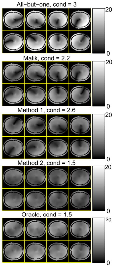
Magnitude of the composite B1 maps (masked), B̃n(r), by different methods, in μT. The condition numbers (cond) of the coil combination matrices are shown on the titles.
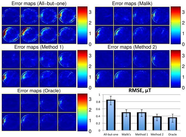
We then simulated the B1 map estimation with the five different coil combinations, where we used the non-regularized method to estimate the B1 magnitude and phase. Fig. 7 shows the resulting B1 magnitude and phase maps for one instance of random noise, and Fig. 8 also shows the error maps of the complex B1 maps, i.e., |B̂ ⊙ eiϕ̂ − B ⊙ eiϕ|, where each pixel value is the average error magnitude over the 20 instances of random noise. As predicted, “method 2” and “oracle method” produced less noisy B1 maps than the other three methods. Despite the model mismatch mainly in B1 magnitude, receive sensitivities and distributions of spin density, T1 and T2, “method 2” still worked similarly well as “oracle method”. In contrast, although “method 1” still improved the B1 estimation compared to the all-but-one method, it did not perform as well as “method 2” and “oracle method”. Moreover, due to the limited flexibility in Malik’s method, it did not improve B1 estimation as much as “method 2” and “oracle method”. The bottom-right part of Fig. 8 shows the RMSEs over all the pixels, defined in (12), of the complex B1 maps reconstructed by the five methods; specifically, it shows the averaged RMSEs of the 20 instances of random noise and the corresponding error bars (shown on top of the averaged RMSE bars).
Fig. 7.
The simulation results of all the methods; left: B1 magnitude estimates (in μT), right: relative B1 phase estimates (in radians).
Fig. 8.
The error maps of the estimated complex B1 maps (in μT) of all the methods and the corresponding RMSEs.
This empirical comparison illustrates that the proposed coil combination optimization can improve the SNR of multi-coil B1 magnitude and phase estimation. Moreover, the proposed methods generally outperform Malik’s method which optimizes only the diagonal entry of A. In addition, the proposed methods are robust to inaccurate magnitude related parameters, e.g., B1 magnitude, receive sensitivities and distributions of spin density, T1 and T2. However, unlike the B1 magnitude estimated by phantom, B1 phase estimates from phantom were far from the true B1 phase in brain, causing the inferior performance of “method 1”. With such big B1 phase mismatch, the improvement of “method 1” over the all-but-one method is mainly from the optimization of the matrix condition number. Since a set of low resolution B1 phase maps takes very minimal scan time in practice, we conclude that “method 2” is the more robust and practical method for the coil combination optimization.
IV. Discussion and Conclusion
We have proposed methods to improve BS B1 mapping for parallel excitation pulse design in the following two main aspects: Estimation quality: the regularized method is proposed to jointly estimate the magnitude and phase of multi-coil B1 maps from BS B1 mapping data, improving estimation quality by using the smoothness of B1 magnitude and phase; Raw data quality: the coil combination optimization based on CRLB analysis is proposed to optimize the SNR of the non-regularized complex B1 estimation over the whole combination matrix. Futhermore, a minor improvement from the proposed method is that it avoids the B1 phase mapping scans that are required for conventional methods.
The cost function for regularized B1 estimation is non-convex, but our experiments have shown that initializing by applying the standard BS B1 mapping and solving (3) is adequate to obtain a good local minimum with our gradient-based optimization algorithm. The CG-BLS algorithm efficiently optimizes the highly nonlinear cost function; a future work can be to design monotonic line search updates to further improve the algorithm efficiency [24]. One disadvantage of regularized estimation is that the regularization parameter is generally difficult to select automatically. In our implementation, the regularization parameters were chosen empirically. Theoretically, the regularization parameters control the spatial resolution of the reconstructed images, so one can select the regularization parameters automatically based on spatial resolution analysis [25]. Furthermore, based on our experience, the proposed algorithm generally converges quickly with 40–120 iterations and 2–3 subiterations depending on the noise level of the initial images.
The modified BS sequence produces a minor improvement on scan time by avoiding the B1 phase mapping scans, but one may argue that the phase mapping scans are collected anyway in “method 2” of the coil combination optimization. However, the coil combination optimization and the regularized reconstruction are independent methods. When one only needs the regularized method and uses a previously optimized coil combination, the proposed B1 mapping method does avoid the B1 phase scans. If one needs both regularized method and coil combination optimization, it may seem redundant to collect B1 phase twice, but the resolution of the B1 phase collected for “method 2” may be too low for pulse design. In addition, for 3D B1 mapping, one may need only one or a few low resolution 2D B1 phase maps for “method 2”, whereas a full 3D phase map may be needed for pulse design.
Our simulation study shows that the optimization results are relatively insensitive to accuracy of T1, T2, spin densities, receive sensitivities and B1 magnitude for 3T brain imaging. Among these magnitude related parameters, the simulation results were more sensitive to different T1 values (results not shown). We empirically found that using uniform maps with the maximal T1 is generally more robust than using other T1 values for this T1 weighted SPGR-based BS sequence. As B1 phase of the phantom is likely to be far from the in-vivo B1 phase, we prefer “method 2” which requires only minimal additional scan time. An alternative to “method 2”would be to compute a library of optimized coil combintations for different imaging anatomies and store them offline. This will require a thorough study about the reproducibility of each optimized coil combination across subjects for each imaging anatomy.
The highly nonlinear and nonconvex coil combination optimization produces random-like combination coefficients, and is highly dependent on the initialization and the pseudo-random seeds used in the SA algorithm, so they are probably not global minimums. However, as we only need to find some combination coefficients that improve the raw data, rather than being the very best choice, the proposed coil combination optimization method is still useful in practice. Even so, further investigations on faster or more robust nonlinear optimization algorithms for this challenging optimization problem will be interesting future work.
Although the optimized coil combination works in practice, this CRLB analysis is only an approximation because the MLE of B1 magnitude and phase are biased estimators in general. Even more estimation bias can be introduced from regularization. Thus, future work could be to design a coil combination optimization based on the biased CRLB analysis [26] which is theoretically valid for regularized estimation.
Although good estimates of B1 maps may be achieved with the all-but-one combinations using the regularized estimation, the proposed coil combinations produce raw data with much better SNR, improving robustness of the regularized estimation method. Sometimes, the optimized coil combination yields adequate B1 estimates without requiring regularization, which may be preferable for practical use.
The proposed coil combination optimization does not con-train specific absorption rate (SAR), which could be a concern in BS B1 mapping sequences. Applying complex weights to PEX channels may cause unpredictable local SAR increase depending on local electromagnetic properties of the tissue [27], so future work can be to consider SAR limits in the coil combination optimization, especially for high field PEX B1 mapping. One could validate that the resulting sequences are within the relevant local SAR limits after the optimization stage, based on local SAR models, e.g., those proposed in [28]–[30]. A better solution would be to incorporate some SAR limit terms or SAR penalty terms to (16), so that SAR constraints can be considered in the coil optimzation stage. Although the unconstrained coil combination optimization may produce SAR problems, the optimization framework provides opportunities for SAR reduction by providing more degrees of freedom for SAR optimized BS pulse design compared to conventional leave-one-out methods.
The simulations for the coil combination optimization used the 2D SPGR sequence, but similar principles can be easily applied for other typical 2D or 3D BS B1 mapping compatible sequences. In addition, improving coil combination is generally important to other multi-coil B1 mapping methods, including both phase-based and magnitude-based methods. Although the proposed method was developed for BS B1 mapping, the framework of the CRLB based coil combination optimization can be applied to other popular multi-coil B1 mapping methods, e.g., AFI [2].
Acknowledgments
This work was supported in part by the National Institutes of Health under Grant R01 NS58576 and Grant P01 CA87634.
The authors would like to thank N. Hollingsworth and K. Moody from Texas A & M University for providing the parallel excitation system, J. Rispoli from Texas A & M University for helping on the B1 map simulation, Dr. J.-F. Nielsen from The University of Michigan for his help in the pulse sequence programming, Dr. D. Yoon from Stanford University and the reviewers for useful suggestions.
Appendix
This appendix shows the detailed derivation for the CRLB analysis discussed in section II.E. Following (14), we can get the log-likelihood, L(θ), and its gradient:
| (19) |
| (20) |
where the superscript H denotes Hermitian transpose, and ∇ denotes column gradient of vectors. Thus, the estimation satisfies the regularity condition, i.e., E(∇L(θ)) = 0. The Fisher information F(θ) of this model is:
| (21) |
According to CRLB, if the estimators [B̂, ϕ̂] are unbiased, their covariance has a lower bound:
| (22) |
Assuming B̂ and ϕ̂ are close to the true values, the variance of B̂eiϕ̂ can be derived by Taylor expansion approximation. For an arbitrary multi-dimensional function g(z), we have:
| (23) |
| (24) |
so if z = (B̂, ϕ̂), g(z) = B̂neiϕ̂, ∇g(z̄) = E[eiϕ, iBeiϕ], and (22) are plugged into (24), we have:
| (25) |
where we have put back the subscripts n, indices r, primes and tildes in (5) except that we put indices r to the subscripts and make A be the argument, as A is the main unknown of this optimization problem.
Assuming that noise in different scans is independent, the covariance of the estimated composite B1 maps is:
| (26) |
Using (9), the covariance of the original individual B1 estimates is:
| (27) |
where z−H ≜ (z−1)H. Since the diagonal entries of the covariance matrix are the variances of the elements of the estimator, plugging in (25) and (26) into (27) yields the key formula of this CRLB analysis, which is (15).
Contributor Information
Feng Zhao, Email: zhaofll@umich.edu, Biomedical Engineering Department, The University of Michigan, Ann Arbor, MI 48109, USA.
Jeffrey A. Fessler, Email: fessler@umich.edu, Department of Electrical Engineering and Computer Science, The University of Michigan, Ann Arbor, MI 48109, USA.
Steven M. Wright, Email: smwright@tamu.edu, Department of Electrical and Computer Engineering, Texas A& M University, College Station, TX 77843, USA.
Douglas C. Noll, Email: dnoll@umich.edu, Biomedical Engineering Department, The University of Michigan, Ann Arbor, MI 48109, USA.
References
- 1.Insko E, Bolinger L. Mapping of the radiofrequency field. Journal of Magnetic Resonance, Series A. 1993;103(1):82–85. [Google Scholar]
- 2.Yarnykh V. Actual flip-angle imaging in the pulsed steady state: A method for rapid three-dimensional mapping of the transmitted radiofrequency field. Magnetic resonance in Medicine. 2007;57(1):192–200. doi: 10.1002/mrm.21120. [DOI] [PubMed] [Google Scholar]
- 3.Sacolick L, Wiesinger F, Hancu I, Vogel M. B1 mapping by Bloch-Siegert shift. Magnetic Resonance in Medicine. 2010;63(5):1315–1322. doi: 10.1002/mrm.22357. [DOI] [PMC free article] [PubMed] [Google Scholar]
- 4.Sacolick L, GWA, Kudielka G, Loew W, Vogel MW. Interference Bloch-Siegert B1 mapping for parallel transmit. Proceedings of the 19th Scientific Meeting of International Society for Magnetic Resonance in Medicine; Montreal, Canada. 2011. p. 2926. [Google Scholar]
- 5.Nehrke K, Bornert P. Improved B1-mapping for multi rf transmit systems. Proceedings of the 16th Scientific Meeting of International Society for Magnetic Resonance in Medicine; Toronto, Canada. 2008; p. 353. [Google Scholar]
- 6.Brunner D, Pruessmann K. B 1+ interferometry for the calibration of rf transmitter arrays. Magnetic Resonance in Medicine. 2009;61(6):1480–1488. doi: 10.1002/mrm.21893. [DOI] [PubMed] [Google Scholar]
- 7.Malik S, Larkman D, Hajnal J. Optimal linear combinations of array elements for B1 mapping. Magnetic Resonance in Medicine. 2009;62(4):902–909. doi: 10.1002/mrm.22068. [DOI] [PubMed] [Google Scholar]
- 8.Zhao F, Fessler J, Nielsen JF, Noll D. Regularized estimation of magnitude and phase of multiple-coil B1 field via Bloch-Siegert B1 mapping. Proceedings of the 20th Scientific Meeting of International Society for Magnetic Resonance in Medicine; Melbourne. 2012; p. 2512. [Google Scholar]
- 9.Zhao F, Fessler JA, Wright SM, Rispoli JV, Noll DC. Optimized linear combinations of channels for complex multiple-coil B1 field estimation with Bloch-Siegert B1 mapping in MRI. Biomedical Imaging: From Nano to Macro, 2013 IEEE International Symposium on. IEEE; 2013; pp. 942–945. [Google Scholar]
- 10.Kirkpatrick S, Gelatt C, Vecchi M. Optimization by simulated annealing. science. 1983;220(4598):671. doi: 10.1126/science.220.4598.671. [DOI] [PubMed] [Google Scholar]
- 11.Brunner D, Pruessmann K. A matrix approach for mapping array transmit fields in under a minute. Quadrature. 2008;60(80):100. [Google Scholar]
- 12.Hua J, Jones C, Blakeley J, Smith S, van Zijl P, Zhou J. Quantitative description of the asymmetry in magnetization transfer effects around the water resonance in the human brain. Magnetic Resonance in Medicine. 2007;58(4):786–793. doi: 10.1002/mrm.21387. [DOI] [PMC free article] [PubMed] [Google Scholar]
- 13.Zhao F, Noll D, Nielsen J, Fessler J. Separate magnitude and phase regularization via compressed sensing. Medical Imaging, IEEE Transactions on. 2012;31(9):1713–1723. doi: 10.1109/TMI.2012.2196707. [DOI] [PMC free article] [PubMed] [Google Scholar]
- 14.Lange K. Numerical analysis for statisticians. Springer; 2010. [Google Scholar]
- 15.[Online]. Available: http://www.bic.mni.mcgill.ca/brainweb/
- 16.Cocosco C, Kollokian V, Kwan K, Pike G, et al. Brainweb: Online interface to a 3D MRI simulated brain database. 1997 [Google Scholar]
- 17.Kwan R, Evans A, Pike G. MRI simulation-based evaluation of image-processing and classification methods. Medical Imaging, IEEE Transactions on. 1999;18(11):1085–1097. doi: 10.1109/42.816072. [DOI] [PubMed] [Google Scholar]
- 18.Kwan R, Evans A, Pike . Visualization in Biomedical Computing. Springer; 1996. An extensible MRI simulator for post-processing evaluation; pp. 135–140. [Google Scholar]
- 19.Collins D, Zijdenbos A, Kollokian V, Sled J, Kabani N, Holmes C, Evans A. Design and construction of a realistic digital brain phantom. Medical Imaging, IEEE Transactions on. 1998;17(3):463–468. doi: 10.1109/42.712135. [DOI] [PubMed] [Google Scholar]
- 20.Hollingsworth N, Moody K, Nielsen J, Noll D, McDougall M, Wright S. Tuning ultra-low output impedance amplifiers for optimal power and decoupling in parallel transmit MRI. Biomedical Imaging: From Nano to Macro, 2013 IEEE International Symposium on. IEEE; 2013. [Google Scholar]
- 21.Moody KL, Hollingsworth NA, Nielsen J-F, Noll D, McDougall MP, Wright SM. Eight-channel transmit/receive head array for use with ultra-low output impedance amplifiers. Biomedical Imaging: From Nano to Macro, 2013 IEEE International Symposium on. IEEE; 2013. [Google Scholar]
- 22.Collins CM, Wang Z, Mao W, Fang J, Liu W, Smith MB. Array-optimized composite pulse for excellent whole-brain homogeneity in high-field mri. Magnetic Resonance in Medicine. 2007;57(3):470–474. doi: 10.1002/mrm.21172. [DOI] [PMC free article] [PubMed] [Google Scholar]
- 23.Haacke EM, Brown RW, Thompson MR, Venkatesan R. Magnetic resonance imaging: physical principles and sequence design. Vol. 1 Wiley-Liss; New York: 1999. [Google Scholar]
- 24.Fessler J, Booth S. Conjugate-gradient preconditioning methods for shift-variant PET image reconstruction. Image Processing, IEEE Transactions on. 1999;8(5):688–699. doi: 10.1109/83.760336. [DOI] [PubMed] [Google Scholar]
- 25.Funai A, Fessler J, Yeo D, Olafsson V, Noll D. Regularized field map estimation in MRI. Medical Imaging, IEEE Transactions on. 2008;27(10):1484–1494. doi: 10.1109/TMI.2008.923956. [DOI] [PMC free article] [PubMed] [Google Scholar]
- 26.Hero AO, III, Fessler JA, Usman M. Exploring estimator bias-variance tradeoffs using the uniform CR bound. Signal Processing, IEEE Transactions on. 1996;44(8):2026–2041. [Google Scholar]
- 27.Alon L, Deniz CM, Brown R, Sodickson DK, Zhu Y. Method for in situ characterization of radiofrequency heating in parallel transmit MRI. Magnetic Resonance in Medicine. 2012 doi: 10.1002/mrm.24374. [DOI] [PMC free article] [PubMed] [Google Scholar]
- 28.Zhu Y, Alon L, Deniz CM, Brown R, Sodickson DK. System and sar characterization in parallel rf transmission. Magnetic Resonance in Medicine. 2012;67(5):1367–1378. doi: 10.1002/mrm.23126. [DOI] [PMC free article] [PubMed] [Google Scholar]
- 29.Katscher U, Voigt T, Findeklee C, Vernickel P, Nehrke K, Dossel O. Determination of electric conductivity and local sar via b1 mapping. Medical Imaging, IEEE Transactions on. 2009;28(9):1365–1374. doi: 10.1109/TMI.2009.2015757. [DOI] [PubMed] [Google Scholar]
- 30.Liu J, Zhang X, Van de Moortele PF, Schmitter S, He B. Determining electrical properties based on b1 fields measured in an mr scanner using a multi-channel transmit/receive coil: a general approach. Physics in medicine and biology. 2013;58(13):4395. doi: 10.1088/0031-9155/58/13/4395. [DOI] [PMC free article] [PubMed] [Google Scholar]


