Abstract
Robust bubble-free priming of complex microfluidic chips represents a critical, yet often unmet prerequisite to enable their practical and widespread application. Towards this end, the usage of a network of capillary stop valves as a generic design feature is proposed. Design principles, numerical simulations, and their application in the development of a microfluidic cell culture device are presented. This chip comprises eight parallel chambers for the assembly and cultivation of human hepatocytes and endothelial cells. The inlet channel divides into cell chambers, after which the flows are reunited to a single chip outlet. Dimensions and geometry of channels and cell chambers are designed to yield capillary burst pressures sequentially increasing towards the chip outlet. Thus, progress of liquid flow through the device is predefined by design and enclosure of air bubbles inside the microfluidic structures is efficiently avoided. Capillary stop valves were designed using numerical simulations. Devices were fabricated in cyclic olefin polymer. Pressure during filling was determined experimentally and is in good agreement with data obtained from simulation.
I. INTRODUCTION
Although microfluidics research is quite advanced in academia, the community is still on the lookout for a blockbuster application in fields such as microfluidic cell culture devices or point-of-care diagnostics. Towards this goal, developers are searching for cost effective and user friendly “Plug and Play” solutions. Injection molding of thermoplastic polymers presents an opportunity for cost effective mass fabrication of microfluidic devices. However, bubble-free filling of complex microstructures or multiplexed channel networks within these hydrophobic polymer devices often presents a major challenge, especially when working with aqueous media.
A common procedure to achieve bubble-free filling of hydrophobic structures involves the application of vacuum to the microfluidic device immersed in liquid followed by reestablishment of pressure, which results in filling of the device.1 While such a process may be acceptable when performing a relatively small number of experiments as needed in academic research it clearly would be prohibitive for routine applications. Hydrophilic materials could alleviate filling by taking advantage of capillary forces effectively pulling the liquid into the structures.2 However, this limits the choice of materials to glass or silicon or requires additional surface treatment of the structures. Therefore, robust bubble-free filling of polymeric microfluidic devices solely by pressure-driven flow is a critical prerequisite for their widespread application.
In order to be applicable in a truly generic manner, the solution to this problem should rely exclusively on geometric features of such devices without the need for additional surface functionalization3,4 to guide flows.
To this end, capillary stop valves represent a unique and versatile design feature to control flow in microfluidic devices. They may easily be introduced by variation of channel geometry.5–8 An abrupt change of channel cross-section will pin the meniscus of the fluid at the edges and stop flow. Flow will continue only upon application of a pressure exceeding the burst pressure of the valve. Burst pressure is a function of surface energy of the liquid-gas-interface, wettability by the fluid, and the geometric dimensions of the valve.9 It therefore can be predefined by an appropriate design of the microfluidic structures.
We applied this paradigm to a network of capillary stop valves inside the HepaChip®, an eight chamber microfluidic system fabricated from cyclic olefin polymer (COP). In the HepaChip, human hepatocytes and endothelial cells are arranged in a liver sinusoid-like fashion by the use of dielectrophoretic forces, thus generating a micro-liver on a chip.10 Complete and bubble-free filling of the cell assembly chambers and perfusion channels of the HepaChip is critical for proper system function.
Based on analytical calculations, microchannels and chambers were designed to comprise capillary stop valves exhibiting burst pressures which increase sequentially towards the chip outlet. In addition, numerical multiphysics simulations were employed to verify and optimize valve function prior to actual manufacture of devices. Finally, filling of devices was investigated, and burst pressures were experimentally verified to be in good agreement with calculations.
In this manuscript, we introduce the concept of achieving bubble-free filling of a hydrophobic microfluidic device by implementing several pressure stages with sequentially increasing pressure towards the device outlet. We illustrate that we are able to design capillary stop valves with the desired burst pressure on the basis of calculations and numerical simulations. By means of pressure measurements inside the HepaChip, an injection molded microfluidic system we show that the theoretically calculated burst pressure stages can be reproduced in experiment.
II. THEORY
Phenomena such as surface tension and wetting properties are negligible in macrofluidics but dominate fluid behavior in micro dimensions. In hydrophobic channel structures such as the HepaChip, the capillary pressure Δpcap acts against the filling pressure Δpin. Capillary pressure Δpcap is calculated from the contact angle θ between the filling liquid and the surfaces of the microchannel, the surface tension γ of the filling liquid and the radius of curvature R of the liquid-air-solid interface.11 Inside a rectangular channel with height h and width w the Young-Laplace equation
| (1) |
with the constraint (2) for both radii of curvature R(h), R(w)
| (2) |
yields the capillary pressure Δpcap.12
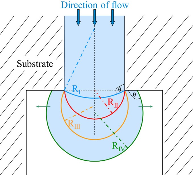
The fact that Δpcap is determined by channel geometry forms the basis of the functionality of a capillary stop valve (Fig. 1). A valve's burst pressure Δpburst denotes the highest attainable capillary pressure at the liquid interface for a given change of channel geometry.
FIG. 1.
Schematic drawing of a liquid-air interface expanding into a channel with abruptly changing width. The radius of curvature R(w) of the liquid-air interface decreases until valve burst pressure Δpburst is reached at the minimum radius of curvature RII (shown in red). The liquid-air interface is pinned at the channel opening during subsequent increase of R(w) until contact angle θ with the adjacent channel wall is re-established.13,14
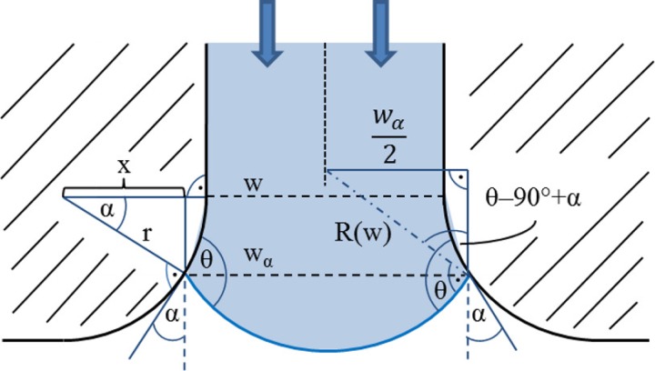
The more realistic case of gradually expanding walls in a microfluidic channel having constant height h is depicted in Fig. 2. The expansion follows a circle with the radius r. The effective channel width wα inside the expansion depends on the opening angle α of the channel walls at the position of the meniscus and is given by
| (3) |
with .
FIG. 2.
Description of parameters w, x, α, r, θ, and wα for calculation of the radius of curvature R(w) of liquid advancing in a gradually opening microfluidic channel. R(w) is calculated using Eq. (4).
The radius of curvature R(w) of the advancing liquid is then calculated using
| (4) |
The burst pressure Δpburst required inside the liquid to overcome a capillary stop valve with gradual expansions on both channel walls is calculated according to
| (5) |
III. MATERIALS AND METHODS
A. Numerical simulations
Structural elements inside the channels and chambers of the HepaChip that are crucial to proper control of flow during priming were identified. Transient 3D two-phase volume of fluid (VOF) based simulations of these microfluidic elements based on CAD data of the microfluidic chambers and the network of channels connecting them were performed using the software CFD-ACE+ (ESI Group, Paris).
The contact angle of the solution domain boundaries was set to the experimentally determined advancing contact angle of 92° (see experimental details). Velocity of the filling liquid at the inlet was calculated from a volumetric flow rate of Q = 100 μl/min and applied uniformly over the area of the inlet. Outlet pressure was set to 0 Pa with reference pressure set at 105 Pa. Simulated forces included gravity () and surface tension forces. For the two fluids in the VOF simulations, we chose air (density , dynamic viscosity at 20 °C) and water (density , dynamic viscosity , surface tension at 20 °C) as the priming liquid. Additional parameters for the VOF filling simulations performed with CFD-ACE+ are comprised in the supplementary material.17
B. Experimental details
HepaChips were injection molded from COP by microfluidic ChipShop (Jena, Germany). Details have been published previously.15 The advancing contact angle of deionized water filling the microfluidic COP channels at 20 °C was determined by evaluation of microscopy images at a volumetric flow rate of <1 μl/min. Flow rate was estimated on the basis of fluid movement over time and channel cross section. The measured advancing contact angle was θ = (92 ± 5.4)° (n = 20).
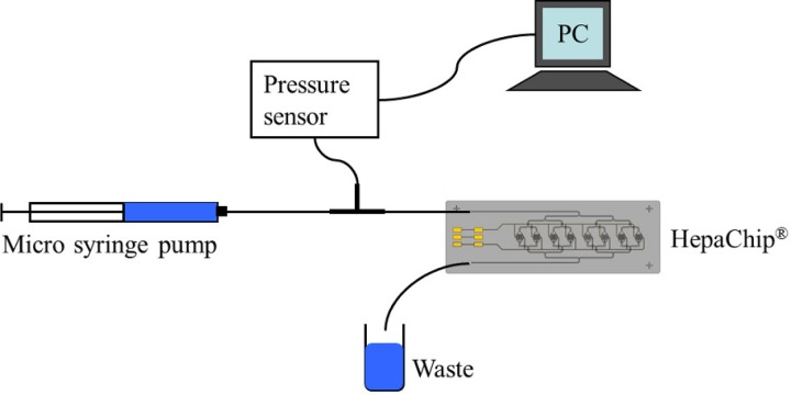
The pressure sensor HCL12X5D (First Sensor AG, Berlin) with a dynamic pressure range between zero and 1250 Pascal was used for the microfluidic pressure measurements. Since the HCL12X5D is built for measurements of gaseous media the silicon membrane had to be protected against corrosion. This was achieved by filling the sensor with low viscosity silicone oil providing for an incompressible connection with the priming liquid. The pressure sensor was connected to a PC via a NI-USB 6212 device (National Instruments Germany GmbH, Munich), and the sensor signal was recorded by in-house LabVIEW (National Instruments Germany GmbH, Munich) software. A micro syringe pump (SP210iw, WPI) enabled priming of the HepaChip at a constant flow rate. A microfluidic bifurcation (P-632, IDEX Health & Science) was used to branch the priming liquid to the pressure sensor and the HepaChip (Fig. 3). The silicone oil–liquid interface was located inside the tubing connecting the pressure sensor to the microfluidic bifurcation. Interface cross section was 0.196 mm2.
FIG. 3.
Schematic drawing of the experimental setup used for pressure measurement.
Prior to connecting the pressure sensor and the HepaChip, air bubble free priming of the PFA tubing and the bifurcation was achieved by rinsing with ethanol. Subsequently, the tubing was filled with water and the pressure sensor, and HepaChip were connected to complete the setup. A calibration of the sensor connected to the experimental setup was established prior to measurement; thus, eliminating effects of oil–liquid interface curvature changes on measured pressure values. Sensitivity of the pressure sensor was 0.013 mV/Pa. In the priming experiments, deionized water and blue dyed deionized water were used. The latter was necessary to localize the fluid in the capillary structures.
C. Issues with priming of chips without capillary trigger valves
Fig. 4 shows an earlier design of the HepaChip without capillary trigger valves. The close-ups depict critical elements such as bifurcations, chamber inlets and outlets, and merging structures. Problems encountered during priming included incomplete priming of chambers and the entrapment of air bubbles in chambers (Fig. 4, right) as there are no elements to control pressure and sequence of priming.
FIG. 4.
(Left, center) Design of the HepaChip without capillary stop valves for flow control, (right) microscope image of an air bubble enclosed during priming of a HepaChip cell assembly chamber with blue dyed deionized water.
D. Design of a capillary stop valve network
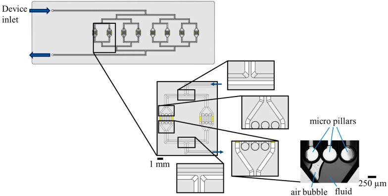
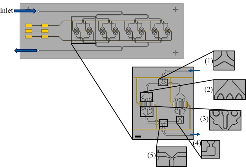
Air bubbles occur inside the microstructures during priming by one liquid-air interface overcoming a junction of two channels before the second liquid-air interface has reached this junction. To allow for fluid flow through the junction exclusively if both interfaces have merged, capillary stop valves with mirrored channel dimensions were implemented at both valve inlet channels, creating a passive trigger valve (Fig. 5, detail (5)). Thus, the liquid-air interface is pinned at one valve site until the second liquid-air interface has reached the second stop valve site. After overcoming the valve's burst pressure, both interfaces are merged at the junction.
FIG. 5.
Channel elements of the HepaChip crucial for flow control during filling: (1) bifurcation of the inlet channel, (2) channel opening into assembly chamber, (3) merging of fluid streams at the chamber outlet, (4) channel constriction after each assembly chamber to ensure even filling of each of the eight chambers, and (5) merging of outlet channels into a single outlet channel. Yellow areas and lines resemble electrodes, connecting pads, and connecting lines intended for the application of high frequency electric fields to the cell chambers during dielectrophoretic assembly of cells. Scale bar 1 mm.
According to Eq. (5), the burst pressure of a capillary stop valve depends on wetting angle θ, channel dimensions w, h, and opening angle α of the channel walls. In this study, variation of channel dimensions are used exclusively to determine valve burst pressure. No surface modifications were applied to change wettability. Channel height was kept constant at h = 190 μm throughout the structures and smooth changes of opening angle of the channel side walls were incorporated instead of abrupt changes. Channel width w of the valves varied between 260 μm and 70 μm.
To ensure bubble-free filling of the eight parallel cell assembly chambers and channels, a network of passive capillary trigger valves was incorporated into the design (Fig. 5). Increasing the burst pressure of the capillary valves sequentially through the microfluidic network ensures even stage-to-stage chip priming, preventing air bubbles from becoming enclosed in individual channel branches.
Based on analytical calculations using Eq. (5), initial design of the capillary stop valves at the stage (1)–(5) in Fig. 5 ensured burst pressure increasing sequentially towards the chip outlet. Numerical simulations were used for optimization of valve geometry and validation of valve function.
IV. RESULTS
A. Simulation results
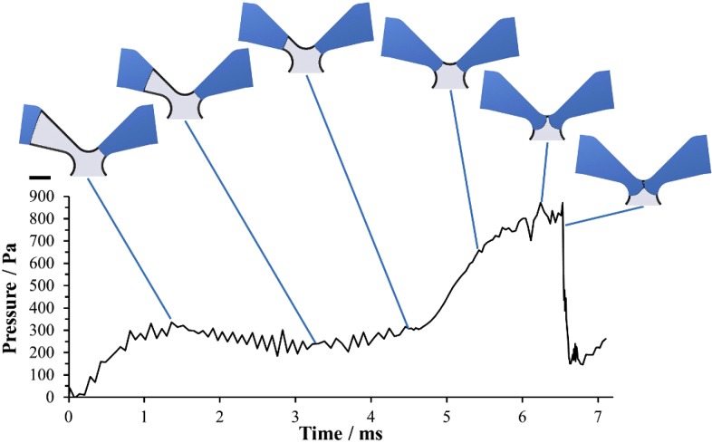
The elements identified as crucial for flow control during filling (Fig. 5) were numerically calculated. As an example, Fig. 6 shows a temporal sequence of simulation results of the merging of fluids from two channels in the outlet merger structure (structure (5) in Fig. 5). The fluid (blue) in the right channel has already reached the merging gap whereas the fluid in the left channel is still moving. The pressure increases as the fluid moves forward in the narrowing channel leading to the merging gap and as the radius of curvature of the meniscus decreases. It peaks when both menisci exhibit minimum radii of curvature shortly before the fluid interfaces join, breaking the capillary valve and forming a new meniscus with a larger radius of curvature. Additional simulation results of the remaining elements are comprised in the supplementary material.17
FIG. 6.
Numerically calculated pressure during priming of the trigger valve merging structure (5) in Fig. 5. Scale bar 200 μm.
B. Experimental results
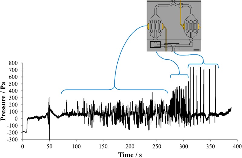
Fig. 7 shows typical results of a pressure measurement during priming of a HepaChip. Sets of pressure transients are clearly visible, which are related to the priming of the channel system and the chambers (structures (1)–(3), Fig. 5) between 70 s and 280 s, the chamber outlet (structure (4), Fig. 5) between 280 s and 310 s and the merger structures (structure (5), Fig. 5) between 310 s and 360 s. The sequential increase of pressure values is also obvious. In Fig. 8, experimental bubble-free priming of the HepaChip with blue dyed deionized water is shown (Multimedia view), illustrating guided liquid flow based on structures (1)–(5), Fig. 5.
FIG. 7.
Pressure recording during chip priming reveals pressure transients related to priming of channels and cell chambers, breaking of chamber outlet valves (structure (4), Fig. 5), and the merging structures at rejoining channels (structure (5), Fig. 5). Scale bar 1 mm.
FIG. 8.
Experimental bubble-free priming of the HepaChip with blue dyed deionized water. Design elements depicted in Fig. 5(1)–(5) regulate liquid flow. Scale bar 3 mm. (Multimedia view) [URL: http://dx.doi.org/10.1063/1.4896063.1]
C. Comparison of results obtained from simulation and pressure measurements
Results obtained from analytical calculation, numerical simulation, and pressure measurements are compiled in Table I. Analytical calculations and numerical simulations were performed using measured contact angle mean value of 92° (see Sec. III B). Estimated errors of the analytical calculations arise from standard deviation ±5.4° in measured contact angle. Calculations using contact angles of 87° and 97° lead to estimated error values of ±87 Pa (inlet bifurcation), ±94 Pa (capillary valve downstream of assembly chamber), and ±149 Pa (outlet channel merging structure).
TABLE I.
HepaChip priming: comparison of pressure values obtained from calculation, simulation, and measurements. Experimental error values derive from statistical variance between measurement data.
| Schematic drawing | Δpburst from analytic calculation using Eq. (5) (Pa) | Δpburst from numeric simulation at 100 μl/min inlet volumetric flow rate (Pa) | Results pburst from pressure measurement in the HepaChip, (n = 4) | |
|---|---|---|---|---|
| Inlet bifurcation |  |
279 | 254 ± 13 | 348 ± 23 |
| Capillary valve downstream of assembly chamber |  |
544 | 514 ± 52 | 538 ± 11 |
| Outlet channel merging structure |  |
809 | 802 ± 36 | 771 ± 11 |
V. DISCUSSION AND CONCLUSION
We introduce the concept of achieving bubble-free filling of a hydrophobic microfluidic device through the establishment of several stages with sequentially increasing valve burst pressure towards the device outlet. We illustrate the design of capillary stop valves with desired burst pressure by means of calculations and numerical simulations. On the basis of pressure measurements inside the HepaChip—an injection molded microfluidic system—we show that the theoretically calculated burst pressure stages can be reproduced in experiment. Both the analytical calculations as well as the numerical simulations are in good agreement with the burst pressures of the valve structures determined experimentally. Analytical calculations and numerical simulations can thus be used for design and optimization of capillary stop valve networks for flow control prior to device fabrication.
The origin of the remaining discrepancies between the data sets presented in Table I (particularly for the inlet bifurcation) is yet unknown. Both in analytical calculation as well as in numerical simulation, surface properties other than contact angle are not taken into account. However, surface texture introduced by the inherently rough surface of the mould employed in the fabrication of these devices or changes in chip substrate material during the bonding process of the cover foil may contribute to variations in experimentally observable burst pressure through minute changes in effective contact angle. As analytical calculations suggest, even minor variations may cause noticeable changes of valve burst pressure: a change of the contact angle by only 3° at the inlet bifurcation would result in a change of valve burst pressure by 54 Pa.
Nevertheless, the data show clearly and reproducibly sequential increase in valve burst pressure towards the device outlet with distinguished differences in burst pressure between the microfluidic valve structures. In particular, the video (Fig. 8) of device priming shows that the structures incorporated to control fluid flow operate as calculated. No gas bubble is enclosed inside the microfluidic structures. Thus, we show successful implementation of our concept of device priming by design into a hydrophobic microfluidic device. However, experiments also suggest that variations in contact angle and surface properties of the injection molded polymer may actually be larger than those covered in our simulations. Thus, the overall yield of chips filled completely bubble-free is not yet satisfactory. In order to enhance robustness of priming the separation of burst pressures has to be increased further.
Priming of the HepaChip is conducted with deionized water prior to cell experiments. The HepaChip however is a chip used for long-term cell culture. Therefore, it is important to provide for an optimal cell environment with respect to shear stresses during injection of cells and subsequent cell culture.16 These requirements put limitations to the freedom of design of the constrictions inside the channels and chambers used for fluid flow control. When used with cells, shear forces can reach critical values in channel constrictions and therefore must be taken into account. Also, cell clogging inside the channel constrictions must be avoided. The minimum cross-section area of such constrictions depending on cell size and sensitivity to shear stress limits the achievable burst pressures to a few 1000 Pa.
The approach presented here can be applied in a generic manner and in particular does not require modification of surface wettability. It thus enables cost effective high volume fabrication of robust priming microfluidic devices.
ACKNOWLEDGMENTS
This work was partially funded by the German Ministry of Education and Research through Grant No. 01GG0729.
Microdevices were manufactured by microfluidic ChipShop. Helpful discussions with Dr. H. Becker are acknowledged.
Proof reading of the manuscript by P. Jones is acknowledged.
B. Hagmeyer performed design, analytical, and numerical calculations, partly performed pressure measurements, and wrote the manuscript, F. Zechnall performed measurements, and M. Stelzle wrote the manuscript and guided research.
References
- 1.Salmanzadeh A., Romero L., Shafiee H., Gallo-Villanueva R. C., Stremler M. A., Cramer S. D., and Davalos R. V., Lab Chip 12(1), 182–189 (2012). 10.1039/c1lc20701f [DOI] [PubMed] [Google Scholar]
- 2.Juncker D., Schmid H., Drechsler U., Wolf H., Wolf M., Michel B., Rooij N. de, and Delamarche E., Anal. Chem. 74(24), 6139–6144 (2002). 10.1021/ac0261449 [DOI] [PubMed] [Google Scholar]
- 3.Feng Y., Zhou Z., Ye X., and Xiong J., Sens. Actuators, A 108(1–3), 138–143 (2003). 10.1016/S0924-4247(03)00363-7 [DOI] [Google Scholar]
- 4.Suk J. W. and Cho J.-H., J. Micromech. Microeng. 17(4), N11 (2007). 10.1088/0960-1317/17/4/N01 [DOI] [Google Scholar]
- 5.Melin J., Roxhed N., Gimenez G., Griss P., van der Wijngaart W., and Stemme G., Sens. Actuators, B 100(3), 463–468 (2004). 10.1016/j.snb.2004.03.010 [DOI] [Google Scholar]
- 6.Cho H., Kim H.-Y., Kang J. Y., and Kim T. S., J. Colloid Interface Sci. 306(2), 379–385 (2007). 10.1016/j.jcis.2006.10.077 [DOI] [PubMed] [Google Scholar]
- 7.Pugia M. J., Blankenstein G., Peters R.-P., Profitt J. A., Kadel K., Willms T., Sommer R., Kuo H. H., and Schulman L. S., Clin. Chem. 51(10), 1923–1932 (2005). 10.1373/clinchem.2005.052498 [DOI] [PubMed] [Google Scholar]
- 8.Zimmermann M., Hunziker P., and Delamarche E., Microfluid. Nanofluid. 5(3), 395–402 (2008). 10.1007/s10404-007-0256-2 [DOI] [Google Scholar]
- 9.Zeng J., Banerjee D., Deshpande M., Gilbert J. R., Duffy D. C., and Kellogg G. J., Micro Total Analysis Systems 2000 ( Kluwer Academic Publishers, 2000), pp. 579–582 [Google Scholar]
- 10.Schütte J., Hagmeyer B., Holzner F., Kubon M., Werner S., Freudigmann C., Benz K., Böttger J., Gebhardt R., Becker H., and Stelzle M., Biomed. Microdevices 13(3), 493–501 (2011). 10.1007/s10544-011-9517-7 [DOI] [PubMed] [Google Scholar]
- 11.Man P., Mastrangelo C., Burns M., and Burke D., paper presented at the Eleventh Annual International Workshop on Micro Electro Mechanical Systems, 1998 (MEMS 98). [Google Scholar]
- 12.Bruus H., Theoretical Microfluidics ( Oxford University Press, New York, 2008). [Google Scholar]
- 13.Tsao C.-W., Liu J., and DeVoe D. L., J. Micromech. Microeng. 18(2), 025013 (2008). 10.1088/0960-1317/18/2/025013 [DOI] [Google Scholar]
- 14.Zechnall F., “ Characterization and conception of polymeric microfluidic systems,” Bachelor thesis, University of Applied Sciences Esslingen, 2013 [Google Scholar]
- 15.Becker H. and Gärtner C., Anal. Bioanal. Chem. 360(1), 89–111 (2008). 10.1007/s00216-007-1692-2 [DOI] [PubMed] [Google Scholar]
- 16.Walker G. M., Zeringue H. C., and Beebe D. J., Lab Chip 4(2), 91–97 (2004). 10.1039/b311214d [DOI] [PubMed] [Google Scholar]
- 17.See supplemental material at http://dx.doi.org/10.1063/1.4896063E-BIOMGB-8-012405 for additional information on simulation parameters and further simulation results.
Associated Data
This section collects any data citations, data availability statements, or supplementary materials included in this article.
Data Citations
- See supplemental material at http://dx.doi.org/10.1063/1.4896063E-BIOMGB-8-012405 for additional information on simulation parameters and further simulation results.


