Abstract
Magnetic Resonance Imaging (MRI) provides superior soft-tissue contrast in cancer diagnosis compared to other imaging modalities. However, the strong magnetic field inside the MRI bore along with limited scanner bore size poses significant challenges. Since current approaches in breast biopsy using MR images is primarily a blind targeting approach, it is necessary to develop a MRI-compatible robot that can avoid multiple needle insertions into the breast tissue. This MRI-compatible robotic system could potentially lead to improvement in the targeting accuracy and reduce sampling errors. A master-slave surgical system has been developed comprising of a MRI-compatible slave robot which consists of one piezo motor and five pneumatic cylinders connected by long pneumatic transmission lines. The slave robot follows the configuration of the master robot, which provides an intuitive manipulation interface for the physician and operates inside the MRI bore to adjust the needle position and orientation and perform needle insertion task. Based on the MRI experiments using the slave robot, there was no significant distortion in the images and hence the slave robot can be safely operated inside the MRI with minimal loss in signal-to-noise ratio (SNR). Ex vivo and in vivo experiments have been conducted to evaluate the performance of the master-slave surgical system.
1 Introduction
Breast cancer, in American women, is the most frequently diagnosed cancer excluding cancers of the skin and is the second leading cause of cancer death, next to lung cancer (American Cancer Society 2012). As a gold standard to confirm if the suspicious tissue is cancerous or not, breast biopsy needs to be guided reliably and accurately to the suspect region to take the tissue sample for microscopic analysis. Since Magnetic Resonance Imaging (MRI) can provide superior soft-tissue contrast (compared to Computed Tomography (CT) and Ultrasound) without any harmful ionizing radiation, it is gaining popularity in recent years, especially in clinical diagnosis. Studies conducted by Lehman et al. (2007) showed that MRI was able to detect cancer in the contralateral breast that was otherwise missed by mammography and clinical examination. Kuhl et al. (2007) showed that MRI could improve the ability to diagnose Ductal carcinoma in-situ (DCIS) with high nuclear grade. Hence, MRI is a competitive candidate for development of image-guided interventions.
The superior soft-tissue contrast provided by MRI comes with the constraint that only limited instruments can be used inside the MRI scanner due to the presence of high magnetic field. The MRI bore size is also relatively small, generally 70 cm in diameter, preventing the physician from accessing the tumor site while the patient is being scanned inside the MRI bore. In current breast biopsy procedures performed under MRI guidance, a coaxial biopsy needle is inserted into the tissue when the patient is outside the MRI bore (Yang et al. 2011b). The trocar needle is removed after the blind targeting to the suspicious region is completed and then the blunt obturator is inserted through the guiding cannula so that the patient can be re-imaged to verify if the desired tumor site has been reached. Once confirmed, the blunt obturator is removed and the biopsy gun is inserted to obtain breast core specimen samples. Thus the primary limitation of the current MR-guided procedure is the need for repeated needle insertion if the initial blind needle targeting is not accurate based on MR images acquired a priori.
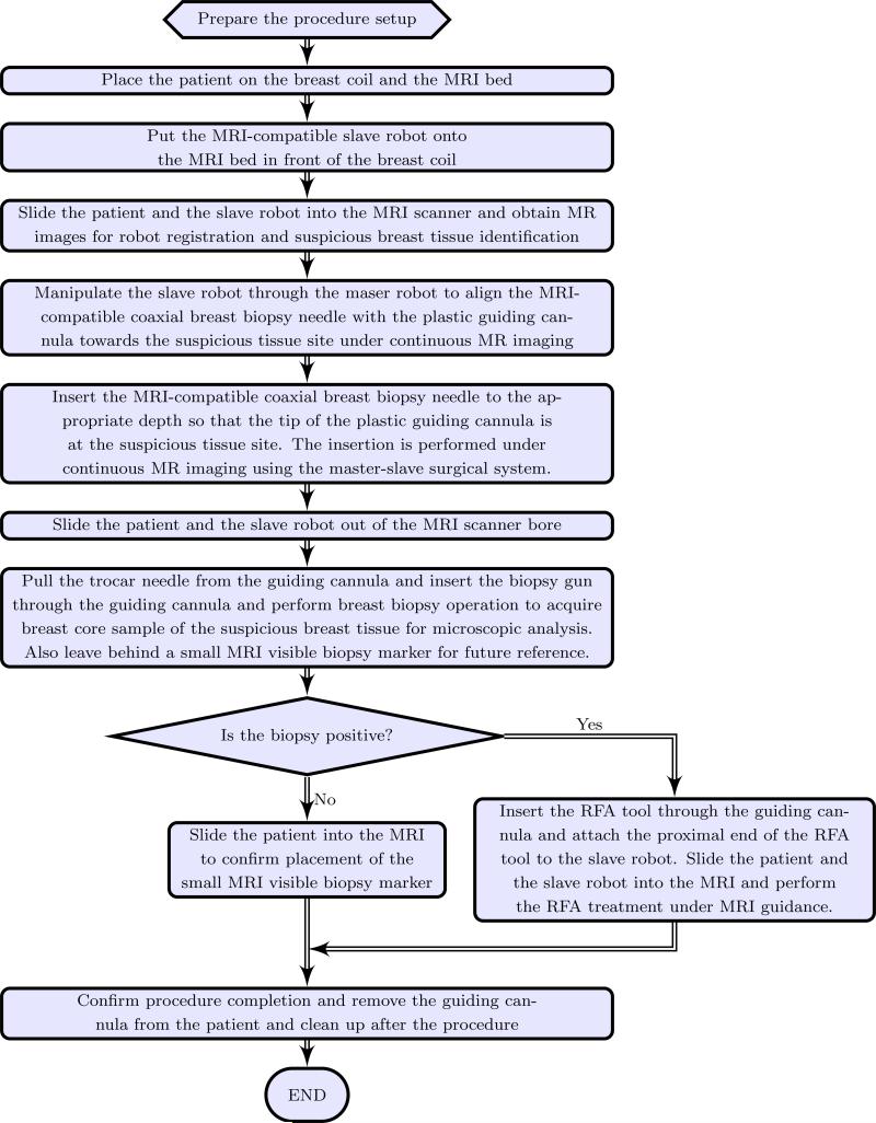
Based on the above motivation, it is desirable to develop a teleoperated MRI-compatible master-slave surgical system that can be used for accurately guiding the biopsy needle to the target tumor site while the patient is in the MRI bore under continuous MR imaging. Though the size of tumors that can be detected could be as small as 1 mm3 on most contrast enhanced 3D T1-weighted imaging techniques, current biopsy systems use an 8 to 14 gauge needle (over 4 to 2 mm in diameter, respectively) and hence target larger lesions compared to the detection limit. The surgical system is expected to perform the needle insertion tasks accurately in one trial, avoiding the repeated needle insertion that could cause undue trauma to the patient. The envisioned work flow of the robotic assisted breast biopsy procedure is shown in Figure 1. MRI-compatible robots that have been developed in the past have primarily focused on prostate therapy (Elhawary et al. 2006b; Fischer et al. 2008; Goldenberg et al. 2008; Krieger et al. 2010; Stoianovici et al. 2007; Su et al. 2011) while MRI-compatible robots for other applications such as one for brain tumor treatment has been developed by Ho et al. (Ho et al. 2011).
Figure 1.
Work flow for the envisioned robot assisted breast biopsy procedure
In the area of MR-assisted breast biopsy there is limited work in the literature, such as a 6 degree-of-freedom (DOF) robotic system developed by Kaiser et al. (2000), remote intervention in the breast by remotely controlling ultrasonic motors (Larson et al. 2004), and a 1 DOF teleoperated needle driver robot (Kokes et al. 2009), are some of the examples. While prior work in this area is mainly geared towards developing a slave robotic system, this paper presents our research in the development of a complete master-slave surgical system.
Based on our initial preliminary work (Yang et al. 2011b, 2012), this paper presents the complete master-slave surgical system, with a 6-DOF MRI-compatible slave robot that can be operated under continuous MRI guidance, as well as extensive ex vivo and preliminary in vivo experimental results. The paper is organized as follows: In Section 2, the latest design of the slave robot is presented, and the mechanism design of the master robot is covered in Section 3. Section 4 describes the system kinematics derivation and Section 5 presents the system integration and control strategy of the master-slave system. The results of teleoperation, the slave robot MRI-compatibility evaluation along with the ex vivo and in vivo targeting experiment results are presented in Section 6 and concluding remarks are made in Section 7.
2 Design and Implementation of the MRI-Compatible Slave Robot
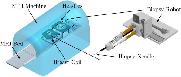
The slave robot is to be placed inside the MRI bore and operated therein and its primary function is to accurately place the guiding cannula using needle insertion under continuous MRI guidance. Through the guiding cannula, diagnostic procedures or treatment such as biopsy and radiofrequency ablation (RFA) can be performed. In a similar configuration to that of a standard breast biopsy procedure, the patient would lie in the prone position on the MRI bed; the slave robot would then access from the front opening of the breast coil and manipulate in the confined space underneath the headrest, as shown in Fig. 2. The circular opening on the top plate of the breast coil is measured to be 150 mm in diameter and the average height between the top and the bottom plate is about 75 mm. Accordingly, the target volume is determined to be a cylindrical space with 125 mm in diameter and 75 mm in height and 5 DOFs are needed to reach points in the 3D space with needle angulation in coronal and sagittal planes.
Figure 2.
The scheme of the MRI-compatible slave robot inside the MRI bore
The slave robot is built with nonmagnetic materials and MRI-compatible actuators to avoid interference with the strong magnetic field inside the MRI bore. Nonmagnetic metals such as brass (Alloy 360) and aluminum (Alloy 3601) have been chosen for the robot structure where higher stiffness and strength is required and they are positioned away from the scanning center to minimize image distortion. Hard plastic such as Delrin® is used for all remaining parts and other parts such as cylinders and linear guides are off-the-shelf components and are chosen to be as less magnetic as possible. Various MRI-compatible actuation techniques have been reviewed by Elhawary et al. (2006a) and pneumatic actuation has been chosen for five out of the six actuating DOFs of the slave robot due to its good MRI-compatibility, linear actuation with high payload (weight) and its cleanness and ease of maintenance compared to hydraulics. For the last DOF, a piezo motor is used to provide rotary actuation and it is placed away from the scanning center to minimize the signal-to-noise ratio (SNR) loss.
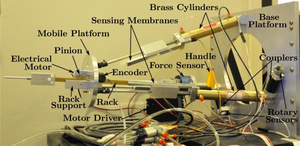
The MRI-compatible slave robot is shown in Fig. 3. It consists of a 1-DOF needle driver actuated with the piezo motor to implement the needle insertion DOF, a 3-DOF pneumatically actuated parallel mechanism that provides needle orientation adjustment, and a 2-DOF X-Y stage that is actuated with two pneumatic cable cylinders to provide the large range motion in the horizontal and vertical directions. Such large range motion cannot be easily provided by a traditional Stewart platform. To facilitate the placement of all electronics and the remaining non MRI-compatible items such as valves away from the scanning center as well as ease of portability of the overall system, the pneumatic cylinders are actuated by long transmission lines (up to 9 m). If needed, however, the length of the transmission lines can be greatly reduced (to 5 m) by moving all the electrical valves into the MRI room with proper RF shielding as demonstrated by Fischer et al. (2008); yet the longer length of the transmission line would make the arrangement of surgical setup more flexible. The detailed design of each subsystem is described in the following subsections.
Figure 3.
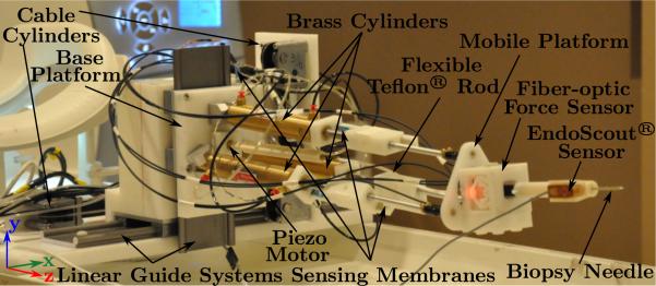
MRI-compatible slave robot
2.1 Needle Driver
In Fig. 4(a) we show the CAD diagram of the needle driver and the actual mechanism used in the experiments is shown in Fig. 4(b). The rotary motion (up to 20 rpm) generated by piezo motor (PiezoMotors, LEGS-R01NM-10) is transmitted via a flexible Teflon® rod to the outer threaded (UNC 3/8-16) needle base to enable flexibility in the placement of the mobile platform. Using a screw structure, this rotary motion is converted into translational motion with a needle insertion speed of 31.75 mm/min at maximum and the modified biopsy needle can be driven back and forth with a designed motion range slightly over 125 mm. The needle is customized from a 12G high field MRI coaxial needle (Invivo, 9896 032 06491) with diamond shaped tip and attached to the needle adaptor with screw threads. The needle adaptor is held by two ceramic bearings (VXB, Kit8707) that are press-fitted into the needle base. This helps isolate the screw motion at the needle base and the friction force between the needle and the tissue during needle insertion prevents the needle from rotating. As a result, we have a pure translation motion of the needle as it is inserted into the tissue. Furthermore, it is important to note that the customized biopsy needle is attached to the needle adaptor by the threaded connection and is easily detachable, making it convenient for single use or customized detachable needles of various sizes that can be easily sterilized. The fixing tube is attached to the needle fixture and holds the needle. It also mounts a MR EndoScout®Sensor (manufactured by Robin Medical Inc.) that can provide the spatial position and orientation of the needle driver in the MRI coordinate. Such fixing tube, along with the needle, could have contact with the patient during insertion and can be disassembled easily for sterilization. In case of emergency such as severe pain, the needle can be retracted manually in a short time by disengaging from its transmission at the end of the flexible Teflon® rod to screw out the needle and detach from the needle driver at the needle base; or in the case of hemorrhage, the needle retraction will be postponed until the physician is prepared to obtain hemostasis.
Figure 4.
The needle driver that can advance the needle without needle rotation.
The needle driver is attached to the parallel mechanism and it passes through the MRI-compatible fiber-optic force sensor (Tan et al. 2011) as shown in Fig. 3. Such force sensor is used to sense the needle tissue interaction force up to 10 N, which is sufficient for a typical 4 N insertion force of a live animal (Maurin et al. 2004).
2.2 Parallel Mechanism
The parallel mechanism uses three 76.2 mm (3”) stroke brass pneumatic cylinders (Allenair, C-7/8×3-BU-L-SZ) serving dual roles of actuators and structural components. The choice of non-magnetic metal cylinders is due to the unavailability of plastic counterparts that can provide sufficient structural strength. Plastic materials are used for the base and the mobile platform (See Fig. 3) to avoid the interference of the induced eddy current, which can be generated inside these relatively bulky parts during slave robot motion if they were made of metal. These three cylinders connect the base platform with pin joints and the mobile platform with kinematically equivalent ball joint (serial connection of a universal joint and a roller bearing), since a small MRI-compatible ball joint was not available. They are placed along circles on the two platforms with identical radius and spaced evenly in 120° increments. In this parallel mechanism, one translational and two rotational DOFs are achieved with coupled motion (Lee and Shah 1988; Pfreundschuh et al. 1994; Yang et al. 2011b) by varying the displacement of the piston in each cylinder and this is illustrated in detail in Section 4. The lengths of the cylinders are controlled by mass flow rate valves that are placed inside the control room.
2.3 X-Y Stage
The X-Y stage employs two pneumatic cylinders to actuate two linear guide systems from igus® (DryLin® WK-10-80-20-01-450 and WK-10-80-10-01-250) and provides two orthogonal translational DOFs in horizontal and vertical directions with a large motion range. It holds the aforementioned parallel mechanism (Fig. 3) from its base platform and helps to position the biopsy needle at the appropriate location along with the parallel mechanism prior to engaging the needle driver mechanism. This enables the placement of the biopsy needle in 3D. The cylinders used in the X-Y stage are one 228.6 mm (9”) stroke and one 101.6 mm (4”) stroke cable cylinder (Tolomatic, 10760032 SK9 and 10760032 SK4, nonmagnetic version of CC07 series), respectively. They provide larger stroke in the limited space of the MRI bore compared to regular cylinders. The position of the cylinder in either direction is measured by the sensing membrane (spectrasymbol, TSP-L-0150-103-1%-RH or TSP-L-0300-103-1%-RH), which is similar to the one used in the parallel mechanism. Thus the combination of the X-Y stage with the parallel mechanism enables arbitrary positioning of the needle within the workspace prior to needle insertion.
3 Design and Implementation of the Master Robot
The master robot is used by the physician to operate the MRI-compatible slave robot and perform the needle insertion task. Hence, it is preferable to have a similar structure as the slave robot to make the operation more intuitive. Additionally, it is also desirable to provide the physician with the needle insertion force along the needle axis through a force-feedback interface. This force feedback can be useful for an experienced physician to determine where the tip is and whether the needle has been inserted into the target tumor. The control of the slave X-Y stage is achieved using keyboard arrow keys, since the x-y motion is straightforward. The developed master robot is shown in Fig. 5. It corresponds to the needle driver and the parallel mechanism of the slave robot to help the physician perform the needle insertion task and the needle orientation adjustment, respectively.
Figure 5.
Master robot
3.1 Needle Driver
The needle driver of the master robot uses a rack and pinion structure and it is fully actuated. Hence it is capable of providing force feedback to the operator during needle insertion into soft-tissue. Such structure has the rack (Quality Transmission Components, BSR0.8-300) held against the rack support along a slot by two small pinions (McMaster, 7880K26). The electrical actuation motor (Sparkfun Electronics, ROB-08912) carries the pinion in front of the mobile platform and is driven by a motor driver (Advanced Motion Controls, 25A8). The encoder (US Digital, S4-250-125-N-D) that provides the needle position information is located on the other side of the mobile platform and holds the second pinion. Between one end of the rack and the handle is a 6-DOF force sensor (JR3, 20E12A-I25) that measures the force exerted by the physician and the electrical motor, which is crucial for force feedback.
3.2 Parallel Mechanism
A similar parallel mechanism as the slave robot is chosen for the master robot to control the orientation of the needle in an intuitive manner. Unlike the parallel mechanism of the slave robot where cylinders are attached to both the mobile and the base platform on circles of the same radius, the cylinders of the master robot are attached to the base platform on a circle with larger radius to allow sufficient space inside the structure for the physician to place his or her hand and manipulate. To achieve similar kinematics of needle orientation, however, the circle radius of both mobile platforms (of the master robot and the slave robot) on which the cylinders are attached are chosen to be identical since the kinematic constraints of the mobile platform depend only on the circle radius, as will be shown in Section 4. In this way, actuator level one-to-one map can be achieved when correlating the configurations of the master robot and the slave robot, as shown in Fig. 7. Cylinders with longer stroke (101.6 mm, 4”) have been chosen (Allenair, C-7/8×4-BU-L-SZ) to cover the motion range of the slave parallel mechanism and their lengths are measured with sensing membranes (spectrasymbol, TSP-L-0150-103-1%-RH). Rotary potentiometric sensors (Novotechnik, PL300 10k0 AA130 FK) are used to measure the rotation angles subtended between the cylinders and the base platform. This information facilitates solving the forward kinematics of the parallel mechanism. Couplers (McMaster, 6208K22) are used to connect the rotary sensors and the pins to which the cylinders are fixed to account for small assembly misalignment.
Figure 7.
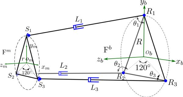
Schematic of the parallel mechanism of the master robot, superposed with that of the slave robot in dotted lines. Si represents the spherical joints of both robots; Ri represents the revolute joints of the slave robot while represents the revolute joints of the master robot; ϕi are the angles subtend between the ith link and the base platform ; Li and are lengths of the extensible links of the slave and the master robot, respectively (i = 1, 2, 3). Both robots share the same frame definition of {Fm} and {Fb}.
4 Kinematics of the Master-Slave System
In this section, we discuss the kinematics of the master and slave robot system. The slave robot consists of the needle driver, the parallel mechanism, and the X-Y stage. The needle driver advances the needle perpendicular to the top mobile platform of the parallel mechanism, while the X-Y stage holds the parallel mechanism and moves it in two orthogonal directions in a decoupled manner. The parallel mechanism, on the contrary, changes the position and orientation of the mobile platform in a coupled and unintuitive way and its kinematics is described in detail. The kinematics of the complete slave robot system is presented in detail below, followed by the kinematic map between the master robot and the slave robot.
4.1 Kinematics of the parallel mechanism
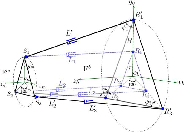
Screw theory is used to derive the inverse kinematics of the three-link parallel mechanism: the coordinates of the spherical joints are determined by the spatial position and orientation of the mobile platform and are compared with those determined at the tip of independent 2-DOF serial manipulators for each of the three extensible links. A preliminary derivation of this method is available in (Yang et al. 2011b) and the complete result is presented as follows. The schematic of a three-link parallel mechanism is shown in Fig. 6.
Figure 6.
Schematic of the parallel mechanism of the slave robot. Si represent the spherical joints on the mobile platform, Ri represent the revolute joints on the base platform and Li are the lengths of the extensible links, (i = 1, 2, 3). Frame {Fm} is attached to the mobile platform on the S1S2S3 plane while frame {Fb} is attached to the base platform on the R1R2R3 plane.
As shown in Fig. 6, the base frame {Fb} is defined to have its xbyb plane lying in the plane determined by the three revolute joints (R1, R2, and R3) with zb-axis pointing upward. Similarly, the mobile frame {Fm} is defined to have its xmym plane lying on the plane determined by the three universal joints (the same points of the kinematically equivalent spherical joints, S1, S2, and S3) with zm-axis pointing upward. The radii of the circumscribed circles of R1R2R3 and S1S2S3 are denoted by R and r, respectively and the link lengths of the parallel mechanisms are L1, L2, and L3. Thus, the homogeneous coordinates of the revolute joints and the spherical joints (i = 1, 2, 3) in their corresponding frames, {Fb} and {Fm}, is:
| (1) |
| (2) |
Using ZYZ Euler angles, the spatial position and orientation of the mobile platform with respect to the base platform can be represented by the corresponding homogeneous transformation matrix, , given by:
| (3) |
where sin θ and cos θ are abbreviated as sθ and cθ respectively (θ = α, β, γ) and is the origin of {Fm} in frame {Fb}. Thus, the coordinates of the spherical joints in the base frame can be derived by:
| (4) |
The coordinates of the spherical joints in the base frame, , can also be obtained as the tip of the corresponding 2-DOF RP manipulator, described by the two joint variables: θi as the rotation angle between the base and link i, and li, the length of the extensible link i. The rotation twist is denoted by ξ2i–1 and the translation twist by ξ2i for the ith link, and they can be written as:
| (5) |
and the forward kinematics map of link i can be computed using the exponential of twists given by:
| (6) |
where gst,i(0) is the initial configuration of link i. The coordinates of the tip of the 2-D manipulator are in the 4th column of gst,i. By comparing the corresponding elements in (4) and (6), nine equations with twelve variables can be acquired, which shows that the mechanism has only 3 degrees of freedom. These nine equations are:
| (7) |
| (8) |
| (9) |
| (10) |
| (11) |
| (12) |
| (13) |
| (14) |
| (15) |
By manipulating equations (10), (11), (13), (14) and combining (7), we have:
| (16) |
Considering the physical constraint that β ≠ ±π, we have:
| (17) |
while requiring . Now, can be solved from (7) and substituting it into the expression obtained after dividing (13) by (14) we obtain . Thus, and are given by:
| (18) |
| (19) |
Thus α, and are independent variables and can be used to determine , , and γ. This further verifies that the mechanism has only three DOFs but will cause motion along xb, yb, and γ, when actuated. Also, it shows that the kinematic constraints of the parallel mechanism depend only on the circle radius r of the mobile platform. When those three independent variables are given, the transformation matrix is determined and can be computed using (4). Thus, the link length Li(i = 1, 2, 3) can be computed using (1) and (4). This derivation enables us to compute the actuator lengths with the desired spatial configuration (translation and orientation of the mobile platform).
The forward kinematics of most parallel mechanisms usually do not have simple explicit form and hence are generally solved using numerical methods. With the previously defined link rotation angles θi, the tip coordinates of the three links have been derived in (6). It is important to note that these three points are the vertices of an equilateral triangle with side length of and hence, the following three equations can be obtained after some simplification:
| (20) |
These equations will be used to iteratively solve for θi numerically. θi values can then be substituted in (6) to compute the spatial position of , which can then be used to solve for the spatial position of the center of the mobile platform, , and is given by:
| (21) |
| (22) |
| (23) |
Comparing the z coordinates of and derived in (6) and those in (4) leads to:
| (24) |
| (25) |
Combining with the result of inverse kinematics derivation in (17)–(19), we have γ = –α, and β can be solved under the following scenarios:
If , then 1 – cβ = 0, hence, β = 0, and α and γ are taken as 0;
- If but , then s2α = 0, hence, , and β can be determined by:
(26) - If but , then c2α = 0, hence, , and β can be determined by:
(27) - If and , then:
(28) (29)
This completes the forward kinematics derivation for the parallel mechanism.
4.2 Kinematics of the Slave Robot
The global world frame {F} (oxyz) attached to the base of the slave robot can be defined to align with frame {Fb} and the link variables of the two cable cylinders that actuate the X-Y stage can be denoted by Xoffset and Yoffset, respectively. The depth of needle insertion is denoted by lN and can be determined independently when performing needle insertion. The depth of needle insertion is defined as the distance from the needle tip to the origin of the mobile platform. The needle orientation (α, β) and tip position (xN, yN, zN) can be correlated with the links variables as:
| (30) |
where , , and are determined by the kinematics of the parallel mechanism.
4.3 Kinematic map of the Master Robot
As shown in Section 4.1, the three-link parallel mechanism is actuated in an unintuitive manner and the solution of the forward kinematics problem requires iterative computation. Using similar kinematic structure as the slave robot for the master robot could mitigate such unintuitiveness, facilitate solving the kinematics, and help validate the desired slave robot configuration. With identical circle radius on the mobile platform as that of the slave robot, the schematic of the parallel mechanism of the master robot superposed with that of the slave robot is shown in Fig. 7.
Since both parallel mechanisms differ only in the circle radii on the base platforms, the length of a master robot cylinder and that of the corresponding slave robot cylinder along with the circle radius difference always form a triangle. Hence, by measuring the master cylinder lengths, , (i = 1, 2, 3) and their angles about the base platform at the pin joints, ϕi, (i = 1, 2, 3), the corresponding cylinder lengths for the slave robot, Li, (i = 1, 2, 3) can be computed using the cosine rule as:
| (31) |
where ΔR = R – r is the radius difference of the two base circles. Hence, actuator level one-to-one map can be established between the corresponding actuators of the master and the slave robots’ parallel mechanism.
5 Control and Integration of the Master-Slave System
5.1 Pneumatic Control of the Slave Robot
In our prior work, we have demonstrated good positioning accuracy using pressure valves (Yang et al. 2011a) and mass flow rate valve (Yang et al. 2011b).
To prevent any electromagnetic interference with the MRI magnetic field, 3/5 mass flow rate proportional valves (Festo, MPYE-5-1/4-010-B) are placed inside the control room. All the cylinders in the slave robot are actuated through long transmission lines (1.5875 mm inner diameter). The control law implemented in the current slave system is a PD control scheme with manually tuned parameters. Coulomb friction compensation has been introduced to reduce the static position error and it is set to be lower than that observed in the experiment to prevent instability problems.
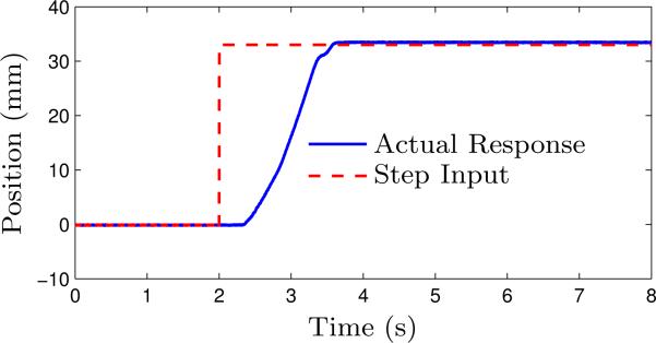
The actual step response of the cable cylinder (0 mm to 33 mm) that actuates the slave robot in the vertical direction is shown in Fig. 8 and it has a payload of 4 kg. In our experiments, we are able to achieve smooth performance of the cable cylinders with a position accuracy of 1 mm. Since the system has static friction, long reaction time is observed in the experiments for all the cylinders.
Figure 8.
Experimental step response of the vertical direction cable cylinder controlled with a mass flow rate valve through long transmission lines.
5.2 Control of the Master Robot
While the cylinders of the master robot are not intended for actuation and only unilateral control is aimed at to enable the intuitive operation for the physician, they are designed to be able to lock as needed to facilitate performing the needle insertion tasks while avoiding involuntary needle orientation change. Six piloted check valves (Festo, HGL-1/8 NPT) are used to shut off each of the cylinder chambers independently. With two pressure valves (tecno plus, PS120100-080-036), the air pressure inside the cylinder chambers can be adjusted in groups of three. When the physician is adjusting the needle orientation, the check valves are open to allow air flow in and out freely and the output pressures of the pressure valves are set to atmospheric pressure so that the cylinders can slide easily to adjust the needle orientation. When the physician has manipulated the needle to the desired configuration and is ready to perform the needle insertion task, the cylinder chambers are pressurized to high pressures (around 350 kPa) and then closed with the check valves to increase the stiffness and lock the cylinders in place.
For the needle driver, proportional control scheme for force and position control is implemented separately to work under different modes: force control is enabled when performing the needle insertion task to provide the necessary needle-tissue interaction force feedback to the physician, while position control is used when the physician is adjusting the needle insertion direction so that it can lock the needle in place to prevent involuntary needle insertion. A proportional feedforward force term is included in the position control scheme to account for the force exerted by the physician and reduce the static position error. The control law can be written as:
| (32) |
where umotor is the electrical motor input voltage; ex and ef are the position error and force error; while Kpx and Kpf are the proportional gains for the position control and the force control, respectively. F is the force sensed by the master robot force sensor along the needle insertion direction and Kpos is the force compensation coefficient in position control.
5.3 Control of the Master-Slave System
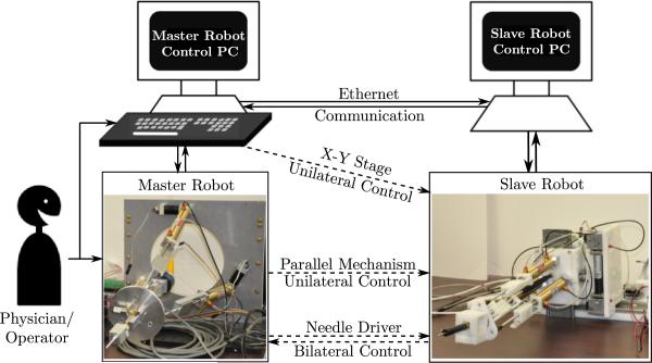
The slave and the master robot each have a control PC with data acquisition cards (Sensoray, Model 626) installed in them to sense and control their configurations. Both the master and the slave robot have the same kinematic structure, which enables actuator level one-to-one mapping for ease of control. Communication between the two control PCs and the exchange of information between them is as shown in Fig. 9.
Figure 9.
Communication protocol between the master and the slave robot — dashed lines indicate virtual connections established via Ethernet communication.
The physician can control the needle insertion into soft-tissue by manipulating the handle in the master robot. To control the X-Y stage of the slave robot, the physician can provide keyboard commands using the arrow keys. The current implementation plans to fix the breast during insertion and manipulation can be performed at any time to readjust the needle orientation as needed at the physician's discretion according to the MR images. It can account for small dislocation of the breast tumor due to tissue deformation when the needle is inserted, though it is not recommended to make large adjustment when the needle has been inserted into the fixed breast tissue. To simplify the master robot structure, only unilateral motion commands for the X-Y stage of the slave robot and the parallel mechanism of the slave robot will be provided by the physician. This will enable control of all five DOFs of the slave robot. Bilateral control is available for the needle insertion DOF to help the physician perform the needle insertion task with force feedback, using the fully actuated needle drivers on both sides (that are capable of both position and force sensing and actuation).
The communication between the master and slave control PCs (Intel® Core™ i5 3.1 GHz CPU, 4 GB memory, and Intel® Gigabit Network Adaptors) is via a dedicated local router and is implemented with Ethernet communication, which can potentially introduce time delays that can deteriorate the control performance or even cause system instability (Hokayem and Spong 2006; Rodríguez-Seda et al. 2009). The time delay from the experiments was measured to be 0.219 ± 0.121 ms under TCP protocol and 0.204 ± 0.120 ms under UDP protocol, which are very small compared to the 500 Hz sampling rate and the time delay associated with pressure transient in the long pneumatic transmission line. Based on the observed experimental data, we neglect the time delay due to network communication and we have chosen TCP protocol in our system due to the simplicity in implementing it as well as its reliability.
6 Experimental Results
Experiments have been conducted to verify the teleoperation capability of the master-slave surgical system, the MRI-compatibility of the slave robot, and finally, ex vivo and in vivo targeting experiments under MRI guidance have been performed.
6.1 Teleoperation of the Master-Slave System
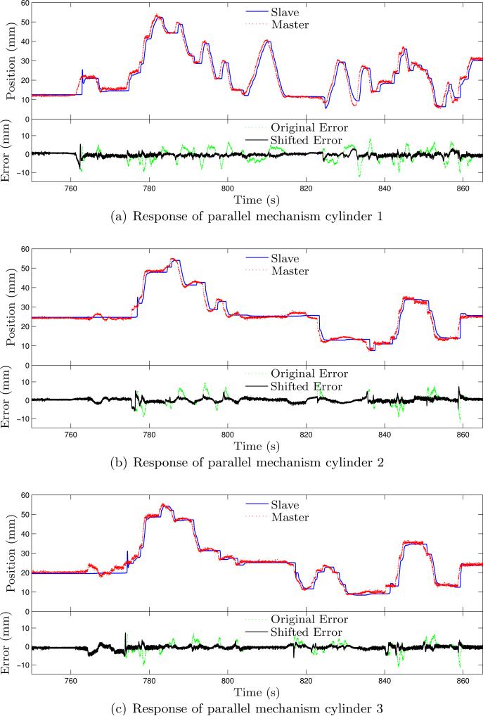
Prior to testing the entire system in MRI, we conducted a test on the integrated master-slave system to verify its functionality. This test comprised of manipulating the master robot arbitrarily and observing the motion of the slave robot. Fig. 10 and Fig. 11 show the response curves along with error plots for both the orientation capability and the needle insertion capability, respectively. Since the motion of the X-Y stage cable cylinders is directly controlled by the keyboard input and due to negligible time delay, the response curve for the motion of the X-Y stage cable cylinders is not shown.
Figure 10.
Experimental results of the master-slave system under free manipulation for needle orientation adjustment. Due to the slow pressure transient of the pneumatic transmission line, the slave robot is significantly delayed with large tracking error. Shifting the response curves of the slave for 0.52 s leads to significantly smaller tracking error.
Figure 11.
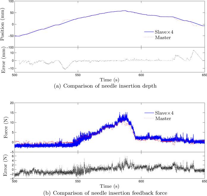
Experimental results of the master-slave system under free manipulation for needle insertion.
Fig. 10 shows the response curves for the slave robot based on the input from the master robot using (31). Relatively large transient tracking error can be observed from those plots and are not unexpected considering the response time limited by the long pneumatic transmission lines. Shifting the position data of the slave robot for 0.52 s prior to the error computation, we can get tracking error with much smaller variation. The average errors of each cylinder with the shifted data are –0.407 ± 0.918 mm, 0.185 ± 1.034 mm, and –0.541 ± 0.957 mm, respectively. This shows the presence of response lag between the slave and the master robot. The slave robot is able to settle at the desired configuration after holding the master robot for several seconds and is in general able to follow the master robot's configuration. A needle insertion task is also performed on a piece of foam (expanded polystyrene (EPS)). The needle used in this test is a customized 8 gauge aluminum needle with sharp cone tip and the resultant curves are shown in Fig. 11(a) and Fig. 11(b). In this test, the motion of the needle in the slave robot is scaled down by a factor of 4, since precise insertion depth is desired and the feedback force is scaled up by a factor of 4 to enhance the force feedback to the physician during needle insertion. Tracking error over 10 mm can be observed for the needle depth and is mainly due to the limited maximum speed of the piezo motor. The force data is quite noisy and larger feedback force would result in larger force tracking error. In general, the slave robot can follow the configuration of the master robot with acceptable errors, which show that the master-slave system is fully functional with reasonable performance.
6.2 MRI-Compatibility Test of the Slave Robot
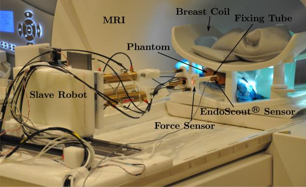
The slave robot is tested in the MRI to verify its MRI-compatibility and the corresponding impact on the MR image quality. The needle used in this test and in the following ex vivo and in vivo tests is the customized Invivo needle described in Section 2.1. The experimental setup is shown in Fig. 12 that the slave robot is placed inside the MRI bore.
Figure 12.
Experimental setup in the MRI.
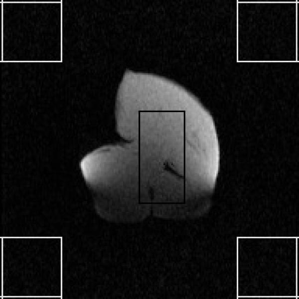
Testing is performed using a 3 T Tim Trio MR scanner (Siemens Medical Solutions; Malvern, PA) with a breast coil and the phantom used is chicken breast purchased at the local supermarket. Dynamic imaging is used for real-time monitoring of the needle insertion along with intermittent high resolution “spot images” after the tumor location is determined from high resolution scans. The dynamic imaging sequence used is a rapid gradient echo sequence (FLASH sequence, TE/TR = 1.5/4.1 – 8 ms, flip angle = 10°, bandwidth = 1302 Hz/pixel, FoV = 300 × 300 mm, matrix = 192 × 192, slice thickness = 3 mm). The dynamic MR images are acquired under various scenarios throughout the procedure of performing a needle insertion task, namely: a) when only the phantom is present in the MRI bore; b) when the robot is put in the MRI bore without any power; c) when the robot is powered on and holding its position; d) when the robot is actuated by its pneumatic actuators to adjust the needle insertion position and orientation; e) when the piezo motor is actuated to perform needle insertion; f) when the robot is retracting the needle; g) when the needle is fully retracted from the phantom; and h) when the robot is powered off in the end. All images can be clearly depicted with no visually-detectable distortion or difference. Fig. 13 shows one of the dynamic images with the piezo motor actuated - one of the scenarios under which the worse image quality is expected.
Figure 13.
Dynamic MR images with the piezo motor actuated.
To quantify the effect of the robot on the MR image quality, the SNR, defined as the ratio of the mean pixel value of signal to the standard deviation of the pixel value of background noise, is calculated. The regions of interest (ROIs) used for this calculation are shown in Fig. 13 and the calculated temporal SNR curve is shown in Fig. 14. The number of frames achieved under each scenario, the number of frames used for average SNR value computation as well as the average SNR value of each series of dynamic images are also summarized in Table 1. Note that the first few frames of each MR image series are excluded from the average SNR computation to allow for the signal to reach steady state.
Figure 14.
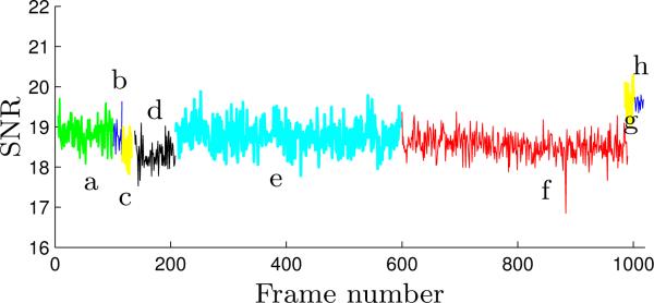
The SNR curve of the dynamic MR images throughout the MRI-compatibility test - the letters denote the aforementioned scenarios under which the dynamic images are acquired.
Table 1.
SNRs of the dynamic MR images under various scenarios with ROIs defined in Fig. 13
| Scenarios | Frames Achieved | Frames Used for SNR Computation | Dynamic Image SNR |
|---|---|---|---|
| a | 100 | 5–100 | 18.85 ± 0.32 |
| b | 20 | 5–20 | 18.80 ± 0.34 |
| c | 20 | 5–20 | 18.45 ± 0.36 |
| d | 80 | 10–80 | 18.31 ± 0.32 |
| e | 400 | 10–400 | 18.78 ± 0.34 |
| f | 400 | 10–400 | 18.54 ± 0.29 |
| g | 20 | 5–20 | 19.63 ± 0.38 |
| h | 20 | 5–20 | 19.61 ± 0.14 |
The SNR values in Table 1 and the SNR curves in Fig. 14 show consistent SNR change. When the robot is placed inside the MRI bore a negligible SNR increase can be observed. Powering on the robot and actuating the robot pneumatically also lead to SNR losses that are small enough to be neglected. The SNR values in Figure 14(e), (g) and (h) are slightly higher than the other five images due to the change in conditions as well as the position of the imaging plane. Throughout the complete procedure under different actuation conditions, the variation of the SNR values is less than 8% even with the spatial variation present.
The acquired MR images and the SNR analysis show that the slave robot does not have any effect on the SNR and also does not induce image distortion. Hence, it can be safely operated inside the scanner with only minimal loss in SNR.
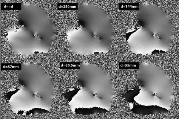
To further test the effect of the robot within the magnetic field with respect to the object being imaged, we generate field homogeneity maps using a large uniform chicken breast and vary the distance of the slave robot to the slice being imaged. The distance of the slave robot measured from the fixing tube of the needle driver varies from 25 cm to 5.5 cm from the imaging volume. Fig. 15 shows the phase images from the chicken breast and are reflective of the field inhomogeneity. As can be seen from Fig. 15 the field is very uniform (< 10 ppm) when the slave robot is not on the table (top left image) and when the slave robot is 25 cm away from the imaging slice. However, this uniformity is disturbed at the periphery of the phantom as the distance between the imaging volume and the slave robot decreases. The field inhomogeneities increase to as high as 40 ppm mainly at the periphery of the phantom while preserving the homogeneity at the center. Such field inhomogeneities have the potential to induce error of greater than 5 mm into the tracking sensor.
Figure 15.
Phase images of the chicken breast with the slave robot at various distances from the phantom. Note that the base of the slave robot is 56.5 cm from the tip of the fixing tube of the robot. Field inhomogeneities increase as the distance between the slave robot and the imaging area of interest decreases. Changes in field homogeneity also affect the tracking accuracy by the EndoScout®.
6.3 Ex Vivo Targeting Test under MR Guidance
During the ex vivo targeting test, the slave robot configuration is tracked with the EndoScout® sensor, which consists of three orthogonal coils and is mounted on the fixing tube of the needle driver. Specialized gradient pulses are embedded into the imaging pulse sequence, and the voltage from these pulses is captured by these coils and digitized at a rate of 20 Hz and converted to determine the location and orientation of the sensor (Hong et al. 2008; Kurumi et al. 2007; Tang et al. 2008). The sensor, in conjunction with the pulse sequence, is pre-calibrated using a special grid that spans the entire diameter and the length of the MR bore which converts the signals to spatial location within the MR machine. The induced voltages in the sensor during actual use are then compared by an optimization algorithm to a previously determined map of this field space to determine the tracking position and orientation of the sensor.
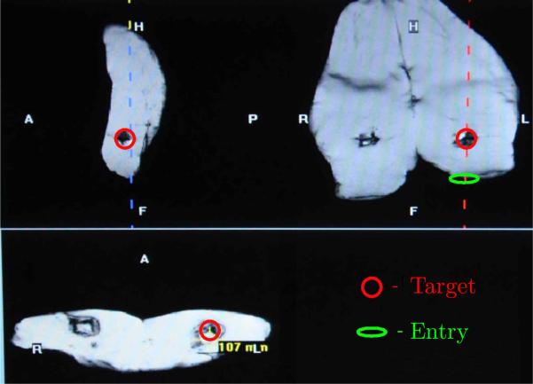
Experiments were performed using samples of chicken breast and a pig leg bought at the local super market that fit between the top and bottom part of a 4-channel breast coil. Markers are placed into the meat samples by placing M4 × 0.7 × 25 mm plastic screws (3 in the chicken breast and 4 in the pig leg sample) at various locations. The leading tip of the plastic screw is considered the target and these targets are approached through robotic intervention from different angles. To perform robot-assisted biopsy under MR guidance, a series of high resolution anatomical images are acquired and used to identify a target location in three orthogonal planes (same sequence used for static imaging in Section 6.2, 0.78 mm in-plane resolution). From these images, along with identifying the target point, the point of insertion is also identified. Once the MR coordinates for the point of insertion are determined, the robot is directed to that location in a manner that the trajectory of the robot is in line with the point of entry and the target within the image. Throughout this process, the location of the fixing tube is continuously monitored from the EndoScout® sensor as shown in Fig. 16.
Figure 16.
Sagittal (top left), coronal(top right) and axial (bottom) images displaying the target in circle within a pig's thigh. The oval shows the entry point where the robot is guided to in a manner that it is directed towards the target as shown in the coronal image.
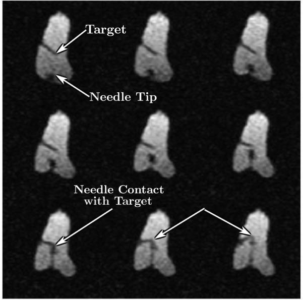
Once the robot is in place, additional imaging is performed to determine the plane of traversal for the needle towards the target using the same high-resolution imaging as described above. Tracking is then performed using rapid gradient echo sequence using 1-3 slices (same sequence used for dynamic imaging in Section 6.2, 1.56 mm in-plane resolution) to ensure that the needle reaches its target. A typical example of reaching the target point from the surface of the skin is shown in Fig. 17.
Figure 17.
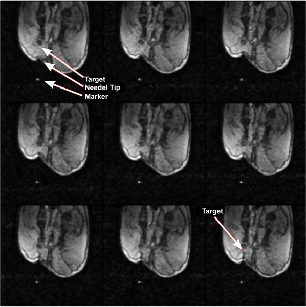
Selected nine frames from continuous MRI as the needle approaches the target. The top left image shows the embedded plastic screw, the tip of which served as the target. The image also shows the entry point for the robot. Advancement of the needle is shown under continuous image guidance in the next few frames. Image on the bottom left shows the needle reaching the target with excellent accuracy. Further advancement of the needle tilts the target as shown by the blue arrows in subsequent frames.
During the 7 trials, the robot comes within 2–4 mm of the target location 6 times, with the targeting being perfect one time as shown in Fig. 17. During one of the trials, the target is missed by about 8 mm. This error is later attributed to the tissue deformation and movement during the robotic manipulation. The average time from initial imaging to reaching (or missing) the target (not including the missed trial) is 20.6 ± 3.5 minutes and the peak insertion force measured along the needle axis ranges from slightly over 1 N to 3 N.
6.4 In Vivo Targeting Test under MR Guidance
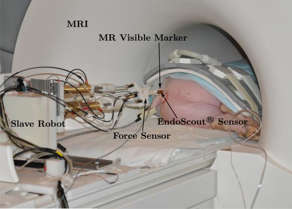
A Yorkshire pig weighing 48 kg is used for testing the master-slave system. The pig is anesthetized using Telazol + Xylazine with 0.25% Bipuvacaine prior to transporting to the MRI center. Anesthesia is continued as needed during the course of the complete experiment. The pig is placed in the magnet sideways in the head first position as shown in Fig. 18. The robotic system is placed at the edge of the magnet on the table top in its default position. The tip of the fixing tube of the slave robot also attaches an MR visible marker so that identification of its location is possible through MR. An 8-channel body array coil is used to image the pig. Once the pig is placed properly on the MRI bed, the deployment time of the developed system is no more than 15 minutes.
Figure 18.
In vivo experimental setup in the MRI
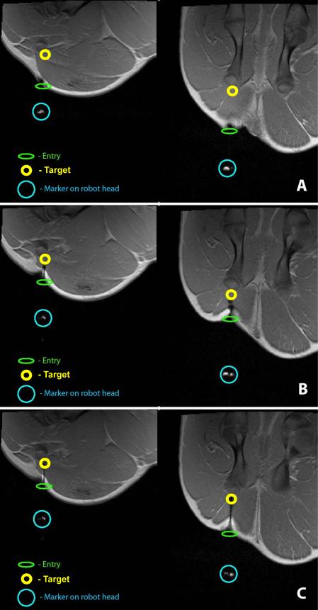
High-resolution images of the thigh muscles of the hind leg are obtained using T1-weighted FLASH sequence (TE/TR = 2.46/440 ms, flip angle = 87°, matrix = 192×192×35, slice thickness = 3 mm, 0.78 mm in-plane resolution) to determine the targeting location. A location 1.5 cm anterior to the femoral bone is chosen as the target as shown in Fig. 19(A) in both the coronal and sagittal planes.
Figure 19.
High-resolution coronal (left) and sagittal (right) spot images at different stages of targeting: (A) target being identified and the robot moved into position to move towards the target; (B) mid-point of targeting; (C) needle reaching the final target location.
Once the target is determined, the entry point and a feasible trajectory to the target are suggested by the physician and the slave robot is moved to line up with the target. Fig. 19 shows the MR visible marker in line with the target. Also shown is the entry point on the pig skin. Once the slave robot is aligned with the target, the MR table is retracted from the center of the bore of the magnet and an incision is made in the skin at the location the robot is pointing. In our envisioned robot-assisted breast biopsy procedure, such incision is also necessary and its location would be determined by advancing a “blunt headed” needle with a marker on the tip. A mark would be made on the breast when it reaches the entry point and would be used as the reference to make the incision. Once the incision is made the pig along with the robot is moved back into the scanner and imaging is resumed. High resolution images are obtained and fine adjustment of the robot is made to ensure that the slave robot is still in position and would advance the needle towards the target through the incision. Dynamic images are then obtained with the slave robot while advancing the needle to the target using rapid imaging sequence (FLASH sequence, TE/TR = 1.5/4.1–8 ms, flip angle = 10°, matrix = 192 × 192, slice thickness = 3 mm, 1.56 mm in-plane resolution) with a frame rate of 2.5 frames per second. Fig. 20 shows some frames from the dynamic session where the needle is advancing towards the target.
Figure 20.
Sample dynamic images in the sagittal plane as the needle is advanced towards the target.
Fig. 19(B) shows the spot high-resolution images with the needle at the mid-point towards the target. Fig. 19(C) shows successful targeting of the planned location. The total time taken from setting up the system to reaching the target takes a little over 50 minutes and the peak insertion force measured along the needle axis is slightly over 6 N, which is within the designed force range.
7 Conclusions
This paper presents the design and experimental evaluation (both ex vivo and in vivo studies) of a teleoperated master-slave surgical system that could potentially be used to perform breast biopsy under continuous MRI, while reducing sampling errors. The slave robot is primarily composed of MRI-compatible materials and actuators, while the master robot is designed to have a similar kinematic structure as the slave robot to enable intuitive operation by the physician. The kinematics of the master-slave system has been discussed in detail, experiments have been conducted to verify the integrated teleoperation capability with reasonable dynamic performance, and force feedback can be provided on the master robot reliably. MRI test on the slave robot and the SNR computation show that the slave robot could operate under continuous MR imaging with no visually-detectable image distortion and minimal loss in SNR, but with mild field homogeneity distortion. The extensive ex vivo targeting experiments confirm that under continuous MR guidance the needle can be inserted to the target position within half an hour and the in vivo experiments show that the needle could be advanced to the desired location.
Following the development of the teleoperated master-slave surgical system, more challenging issues need to be addressed to meet the clinical requirement of breast biopsy procedures. First and foremost, the footprint of the slave robot should be further minimized to gain easy access to extreme locations from superior and inferior directions. Work should also be performed to refine the slave robot implementation by removing any sharp edges and incorporate as much plastic components as possible in a manner that it does not induce stray fields that might interfere with the accuracy of the position sensor. Secondly, a special breast coil should be built that is optimized for use in conjunction with the robot and maximize the access space provided to the breast. Strategies should be developed that involves the use of a compression pad that can better fix the breast and further minimize its gross motion during the targeting process in order to minimize the movement of tumor inside the breast. Path planning can also be investigated to develop tissue models that can be used to predict the tumor movement due to large tissue deformation and avoid the need for large needle adjustment. Thirdly, the emergency plan should be investigated and dedicated mechanism should be implemented such that the inserted needle can be easily disengaged from the slave robot, allowing the physician to remove the needle carefully after the patient has been removed from the MRI scanner. Currently, a graphical user interface (GUI) that would integrate seamlessly with the operation of the robotic system and the MR scanner is under active development and would aid in procedure time reduction and reaching the goal of half-hour once the patient is on the table. This GUI will communicate with the position server of the EndoScout® sensor as well, which would facilitate the evaluation of the slave robot motion accuracy inside the MRI scanner. A biopsy gun and an RF-ablator will also be used during future evaluation studies.
Footnotes
This work was supported by the National Institutes of Health (NIH) [1R01EB008713].
References
- American Cancer Society Cancer Facts & Figures 2012. American Cancer Society, Atlanta. 2012 [Google Scholar]
- Elhawary H, Zivanovic A, Davies B, Lampérth M. A review of magnetic resonance imaging compatible manipulators in surgery. Proceedings of the Institution of Mechanical Engineers. Part H, Journal of Engineering in Medicine. 2006a;220(3):413–424. doi: 10.1243/09544119JEIM73. [DOI] [PubMed] [Google Scholar]
- Elhawary H, Zivanovic A, Rea M, Davis B, Besant C, McRobbie D, de Souza N, Young I, Lampérth M. The feasibility of MR-image guided prostate biopsy using piezo-ceramic motors inside or near to the magnet isocentre.. In: Larsen R, Nielsen M, Sporring J, editors. International Conference on Medical Image Computing and Computer Assisted Intervention, volume 4190 of Lecture Notes in Computer Science; Berlin / Heidelberg. Springer; 2006b. pp. 519–526. [DOI] [PubMed] [Google Scholar]
- Fischer GS, Iordachita I, Csoma C, Tokuda J, DiMaio SP, Tempany CM, Hata N, Fichtinger G. MRI-compatible pneumatic robot for transperineal prostate needle placement. IEEE/ASME Transactions on Mechatronics. 2008;13(3):295–305. doi: 10.1109/TMECH.2008.924044. [DOI] [PMC free article] [PubMed] [Google Scholar]
- Goldenberg AA, Trachtenberg J, Kucharczyk W, Yi Y, Haider M, Ma L, Weersink R, Raoufi C. Robotic system for closed-bore MRI-guided prostatic interventions. IEEE/ASME Transactions on Mechatronics. 2008;13(3):374–379. [Google Scholar]
- Ho M, Koltz M, Simard JM, Gullapalli R, Desai JP. Towards a MR image-guided SMA-actuated neurosurgical robot.. IEEE International Conference on Robotics and Automation; Shanghai, China. 2011. pp. 1153–1158. [Google Scholar]
- Hokayem PF, Spong MW. Bilateral teleoperation: An historical survey. Automatica. 2006;42(12):2035–2057. [Google Scholar]
- Hong J, Hata N, Konishi K, Hashizume M. Real-time magnetic resonance imaging driven by electromagnetic locator for interventional procedure and endoscopic therapy. Surgical Endoscopy. 2008;22(2):552–556. doi: 10.1007/s00464-007-9633-x. [DOI] [PubMed] [Google Scholar]
- Kaiser WA, Fischer H, Vagner J, Selig M. Robotic system for biopsy and therapy of breast lesions in a high-field whole-body magnetic resonance tomography unit. Investigative Radiology. 2000;35(8):513–519. doi: 10.1097/00004424-200008000-00008. [DOI] [PubMed] [Google Scholar]
- Kokes R, Lister K, Gullapalli R, Zhang B, McMillan A, Richard H, Desai JP. Towards a teleoperated needle driver robot with haptic feedback for RFA of breast tumors under continuous MRI. Medical Image Analysis. 2009;13(3):445–455. doi: 10.1016/j.media.2009.02.001. [DOI] [PMC free article] [PubMed] [Google Scholar]
- Krieger A, Iordachita I, Song S-E, Cho NB, Guion P, Fichtinger G, Whitcomb LL. Development and preliminary evaluation of an actuated MRI-compatible robotic device for MRI-guided prostate intervention.. IEEE International Conference on Robotics and Automation; Anchorage, Alaska, USA. 2010. pp. 1066–1073. [Google Scholar]
- Kuhl CK, Schrading S, Bieling HB, Wardelmann E, Leutner CC, Koenig R, Kuhn W, Schild HH. MRI for diagnosis of pure ductal carcinoma in situ: a prospective observational study. The Lancet. 2007;370(9586):485–492. doi: 10.1016/S0140-6736(07)61232-X. [DOI] [PubMed] [Google Scholar]
- Kurumi Y, Tani T, Naka S, Shiomi H, Shimizu T, Abe H, Endo Y, Morikawa S. MR-guided microwave ablation for malignancies. International Journal of Clinical Oncology / Japan Society of Clinical Oncology. 2007;12(2):85–93. doi: 10.1007/s10147-006-0653-7. [DOI] [PubMed] [Google Scholar]
- Larson BT, Erdman AG, Tsekos NV, Yacoub E, Tsekos PV, Koutlas IG. Design of an MRI-compatible robotic stereotactic device for minimally invasive interventions in the breast. Journal of Biomechanical Engineering. 2004;126(4):458–465. doi: 10.1115/1.1785803. [DOI] [PubMed] [Google Scholar]
- Lee K-M, Shah DK. Kinematic analysis of a three-degrees-of-freedom in-parallel actuated manipulator. IEEE Journal of Robotics and Automation. 1988;4(3):354–360. [Google Scholar]
- Lehman CD, Gatsonis C, Kuhl CK, Hendrick RE, Pisano ED, Hanna L, Peacock S, Smazal SF, Maki DD, Julian TB, DePeri ER, Bluemke DA, Schnall MD. MRI evaluation of the contralateral breast in women with recently diagnosed breast cancer. The New England Journal of Medicine. 2007;356(13):1295–1303. doi: 10.1056/NEJMoa065447. [DOI] [PubMed] [Google Scholar]
- Maurin B, Piccin O, Bayle B, Ganglo J, de Mathelin M, Soler L, Gangi A. A new robotic system for CT-guided percutaneous procedures with haptic feedback. International Congress Series. 2004;1268:515–520. [Google Scholar]
- Pfreundschuh GH, Sugar TG, Kumar V. Design and control of a three-degrees-of-freedom, in-parallel, actuated manipulator. Journal of Robotic Systems. 1994;11(2):103–115. [Google Scholar]
- Rodríguez-Seda EJ, Lee D, Spong MW. Experimental comparison study of control architectures for bilateral teleoperators. IEEE Transactions on Robotics. 2009;25(6):1304–1318. [Google Scholar]
- Stoianovici D, Song D, Petrisor D, Ursu D, Mazilu D, Mutener M, Schar M, Patriciu A. “MRI Stealth” robot for prostate interventions. Minimally Invasive Therapy. 2007;16(4):241–248. doi: 10.1080/13645700701520735. [DOI] [PMC free article] [PubMed] [Google Scholar]
- Su H, Zervas M, Cole GA, Furlong C, Fischer GS. Real-time MRI-guided needle placement robot with integrated fiber optic force sensing.. IEEE International Conference on Robotics and Automation; Shanghai, China. 2011. pp. 1583–1588. [Google Scholar]
- Tan U-X, Yang B, Gullapalli R, Desai JP. Triaxial MRI-compatible fiber-optic force sensor. IEEE Transactions on Robotics. 2011;27(1):65–74. doi: 10.1109/TRO.2010.2090061. [DOI] [PMC free article] [PubMed] [Google Scholar]
- Tang AM, Kacher DF, Lam EY, Wong KK, Jolesz FA, Yang ES. Simultaneous ultrasound and MRI system for breast biopsy: compatibility assessment and demonstration in a dual modality phantom. IEEE Transactions on Medical Imaging. 2008;27(2):247–254. doi: 10.1109/TMI.2007.911000. [DOI] [PubMed] [Google Scholar]
- Yang B, Tan U-X, McMillan A, Gullapalli R, Desai JP. Design and control of a 1-DOF MRI compatible pneumatically actuated robot with long transmission lines. IEEE/ASME Transactions on Mechatronics. 2011a;16(6):1040–1048. doi: 10.1109/TMECH.2010.2071393. [DOI] [PMC free article] [PubMed] [Google Scholar]
- Yang B, Tan U-X, McMillan A, Gullapalli R, Desai JP. Design and implementation of a pneumatically-actuated robot for breast biopsy under continuous MRI.. IEEE International Conference on Robotics and Automation; Shanghai, China. 2011b. pp. 674–679. [Google Scholar]
- Yang B, Tan U-X, McMillan A, Gullapalli R, Desai JP. Towards the development of a master-slave surgical system for breast biopsy under continous MRI.. the 13th International Symposium on Experimental Robotics; Québec City, Canada. 2012. In Press. [DOI] [PMC free article] [PubMed] [Google Scholar]


