

Abstract
β-hairpin peptide-based hydrogels are a class of injectable solid hydrogels that can deliver encapsulated cells or molecular therapies to a target site via syringe or catheter injection as a carrier material. These physical hydrogels can shear-thin and consequently flow as a low-viscosity material under a sufficient shear stress but immediately recover back into a solid upon removal of the stress, allowing them to be injected as preformed gel solids. Hydrogel behavior during flow was studied in a cylindrical capillary geometry that mimicked the actual situation of injection through a syringe needle in order to quantify effects of shear-thin injection delivery on hydrogel flow behavior and encapsulated cell payloads. It was observed that all β-hairpin peptide hydrogels investigated displayed a promising flow profile for injectable cell delivery: a central wide plug flow region where gel material and cell payloads experienced little or no shear rate and a narrow shear zone close to the capillary wall where gel and cells were subject to shear deformation. The width of the plug flow region was found to be weakly dependent on hydrogel rigidity and flow rate. Live-dead assays were performed on encapsulated MG63 cells three hours after injection flow and revealed that shear-thin delivery through the capillary had little impact on cell viability and the spatial distribution of encapsulated cell payloads. These observations help us to fundamentally understand how the gels flow during injection through a thin catheter and how they immediately restore mechanically and morphologically relative to pre-flow, static gels.
1. Introduction
To facilitate future biomedical treatment with localized delivery and higher therapy efficacy, much research effort has been devoted recently to the development of biomaterials to transport a therapy to in vivo target sites via simple syringe or catheter injection.1,2 Hydrogels are a major type of potential injectable therapeutic delivery vehicle. The porous and highly hydrated nature of hydrogels can be utilized for encapsulation and delivery of therapeutics including growth factors3-5, small molecule drug6-9, proteins10-12 and cells13-20.
Most injectable hydrogel materials are free flowing precursor solutions ex vivo that become covalently crosslinked or physically crosslinked via self-assembly into hydrogels once injected in vivo in response to exposure to a temperature change16,21, ions3,10,22, enzymes23,24 or ultraviolet radiation11,25. On one hand, the free flowing property renders these precursor solutions injectable as low viscosity liquids that can easily fill in vivo tissue defects and cavities26. On the other hand, undesired leakage of these free flowing solutions to neighboring tissue or blood vessels can happen unless the injected liquid is constrained within the filled defect by the natural boundary of the defect. In some studies, hydrogel precursor solutions with higher viscosity27 or fast in situ gelation kinetics were adopted in order for quick retention of injected liquids. However, it is still possible that the injected precursor solution may be diluted by local bodily fluids or impacted by the local environment before, during and after cross-linking, leading to ambiguous, final hydrogel material properties that are unpredictable through in vitro experiments.
An alternate strategy for injectable hydrogels focuses on the development of shear-thinning and self-healing9,10,16-20,28-31 solid hydrogels preformed in vitro with desired mechanical, structural, and biological properties. These gels are injectable because they shear-thin and consequently flow under a shear stress above the yield point but immediately recover back into solids directly after the shear stress is removed.20 The shear-thinning and immediate rehealing behavior make these gels promising candidates for injectable therapeutic delivery vehicles; the shear-thinning property allows the gel and payload encapsulated during initial peptide self-assembly, and consequent hydrogelation, to be delivered to an in vivo target site via simple syringe or catheter injection while the immediate gel self-healing property enables the administered gel and therapeutics to remain localized at the delivery site.19,20,32 The final gel material in vivo will exhibit the same properties as the hydrogel displays ex vivo, enabling one to completely define the properties of delivered hydrogel and engineer biomedical outcomes as desired.20
We have developed a variety of β-hairpin peptides19,30,33-38 that self-assemble into physical hydrogels in response to various environmental stimuli including pH30 or temperature change33, salt31, or UV light exposure34. β-hairpin peptide hydrogels display shear-thinning and immediate recovery properties9,19,20,30,31; the solid peptide hydrogel preformed in a syringe can be injected as a solid through a needle and precisely delivered to a target site with instant recovery into a solid post-injection9,19,20. In addition, these β-hairpin peptide gel materials can be inherently antibacterial36, are biologically benign toward several model cell lines19,20,39,40 and unable to provoke immune-responses in macrophages in vitro41. Moreover, the gel properties (e.g. gelation kinetics, gel stiffness, network mesh size) can be readily adapted for cell encapsulation or controlled release of desired therapeutics by modulating peptide sequence, peptide concentration, solution ionic strength and/or temperature.8,9,19,42,43 All of these material properties suggest that these solid hydrogels are promising candidates as vehicles for injectable therapeutic delivery and for drug delivery and/or tissue regeneration.
The peptide used in this study, MAX8 (VKVKVKVK-VDPPT-KVEVKVKV-NH2), is constituted by a tetra-peptide turn sequence (-VDPPT-) and two neighboring β strands of alternating hydrophobic valine (V) residues and hydrophilic lysine (K) residues19, except that the lysine residue at position 15 is replaced by a glutamic acid (E) residue. When MAX8 peptide is dissolved in physiological pH solution with low ionic strength, it is unfolded and of a random coil-like conformation because of the positively charged nature of lysine side groups. However, intramolecular folding of MAX8 peptides can be triggered by a combination of adding salt to screen electrostatic repulsions between lysines, by elevating temperature to induce hydrophobic collapse or by deprotonation of the lysines at basic pH8,19. As a result of the intramolecular folding conformation change into a β-hairpin, the folded peptides self-assemble into a stiff hydrogel with a three-dimensional, nanofibrillar network structure stabilized by physical crosslinks9,39 that allow the hydrogel to shear-thin and flow into a thin catheter9,19,20. Due to fast gelation kinetics under physiological condition, MAX8 is capable of encapsulating living mammalian cells homogeneously in three-dimensions during initial hydrogelation, which is exactly desired for injectable delivery of cells19,20. Furthermore, it was observed that encapsulated cells were still viable and evenly distributed in three dimensions after shear-thin delivery through a syringe needle19,20, implying the potential of these hydrogels as excellent candidates for injectable cell delivery due to their unique shear-thinning and recovery properties.
In a previous study, we elucidated the underlying mechanisms of β-hairpin peptide hydrogel shear-thinning and immediate self-healing properties by investigation of hydrogel network behavior during and subsequent to flow in a parallel plate geometry with a torsional rheometer and in a large capillary geometry having a large 1.5 mm of inner-diameter (ID) with neutron and x-ray scattering20. However, it is critical to assess the flow behavior of the hydrogel in a much smaller capillary geometry used in actual therapeutic delivery in order to better understand hydrogel feasibility as a carrier material. Also it is necessary to quantitatively study the effect of shear during injection on hydrogel flow behavior as the entry of materials into, and flow of materials through, a capillary geometry is known to cause significant amounts of shear and deformation in a material depending on the material properties. In addition, the application of mechanical shear on cells can significantly change cell biological behavior16,17,44-50. It is important to state that while some cells are normally exposed to high shear flow (e.g. red blood cells51, endothelial cells52, fibroblasts53), many other cells considered for in vivo tissue regeneration therapy are normally not subject to significant shear forces19,20. Therefore, it is essential to assess effect of capillary flow on encapsulated cell payloads under injection flow conditions. Therefore, the primary novelty of the current contribution is our first observations and quantifications of capillary flow profiles for β-hairpin peptide hydrogels in a clinically-relevant delivery geometry. In this work, instrumentation was integrated with a laser-scanning confocal microscope (LSCM) designed to quantitatively measure rheological properties of hydrogels and encapsulated cell payloads within a circular capillary that has the same ID (250μm) as a 26-gauge syringe needle. Instead of simulating material flow within a syringe needle17, direct visualization of the flowing material structure under different flow rates was used, a technique frequently adopted to study the effect of flow on gel structure and flow behavior in colloidal gels54-57 and recently yielding behavior of telechelic protein hydrogels16. These measurements clarify how the flow behavior of hydrogel and encapsulated payloads depend on gel rigidity and flow rate. The results also demonstrate favorable gel flow profiles for shear-thin delivery of encapsulated cells, which is significant for further understanding of hydrogel injectability and immediate recovery properties after injection.
2. Experimental Section
2.1 Materials and Hydrogel Preparation
HEPES was purchased from Sigma Aldrich; Dulbecco's Phosphate-Buffered Saline (DPBS), Fetal Bovine Serum (FBS), trypsin-EDTA, Penicilin-Streptomycin, Dulbecco's Modification of Eagle's Medium (DMEM, 1×) were purchased from Cellgro by Mediatech; and 1× DMEM with 25mM HEPES (pH 7.4) was purchased from Gibco by Invitrogen. MAX8 (VKVKVKVK–VDPPT-KVEVKVKV-NH2) peptide was synthesized on Rink amide resins with an automated SONOTA peptide synthesizer employing standard Fmoc-protocol and HCTU activation. Detailed description of peptide synthesis and purification is available in a previously published protocol19,58. MAX8 hydrogels were prepared under conditions mimicking the physiological. To prepare a 0.5wt% and a 0.75 wt% MAX8 gel, 4 mg and 6 mg pure MAX8 peptide were individually dissolved in separate 400 μL 25 mM HEPES buffer (pH 7.4) to produce 1wt% and 1.5 wt% peptide solution. Then 400 μL 1× DMEM with 25 mM HEPES (pH 7.4) was added to each peptide solution to initiate gelation.
2.2 Rheological Characterization
Hydrogel viscoelastic properties were examined via oscillatory rheology experiments performed on an AR-2000 rheometer (TA Instruments) using a 20 mm-diameter acrylic, cross-hatched parallel plate geometry tool. Each buffered MAX8 peptide solution was prepared in ice-chilled condition to prevent thermal gelation and was then immediately transferred to the rheometer bottom plate that was pre-equilibrated at 5 °C. The matching parallel plate was then quickly lowered to the desired gap height of 0.5 mm. To prevent sample drying during measurements, a NIST traceable standard S3 mineral oil (Cannon Instruments, η ≈ 3 m·Pa s at 22 °C) was applied around the plate geometry tool. Then the temperature was linearly and quickly raised to 37 °C to initiate gelation. First, time-dependent growth of storage (G′) and loss (G″) moduli during hydrogelation was monitored in a dynamic time sweep at a frequency of 6 rad·s-1 and 0.2% strain until an equilibrated gel was formed on the rheometer. Then a dynamic frequency sweep (0.1-100 rad s-1, 0.2% strain) was performed to investigate whether gel stiffness was independent of frequency. A dynamic strain sweep (6 rad·s-1 and 0.1-1000% strain) was subsequently performed on the same gel sample to determine the linear viscoelastic region, the results of which are provided in the SI. All viscoelastic properties were determined in the linear viscoelastic region. Three independent MAX8 hydrogels for each peptide concentration (six samples in total) were examined using this oscillatory rheology protocol. In addition, MAX8 gels with encapsulated polystyrene microspheres or MG63 cells were also examined using the same protocol.
2.3 Hydrogel Flow Measurement
Red fluorescent carboxylate-modified polystyrene (PS) microspheres (15 μm in diameter) in H2O were purchased from Invitrogen. To prepare a 0.5 wt% MAX8 hydrogel sample that encapsulates the microspheres, 150 μL of buffered bead suspension (1×10⁴ beads/mL, 25mM HEPES, pH 7.4) was added to an equal volume of 2 wt% or 3 wt% MAX8 peptide solution (25mM HEPES, pH 7.4). After subsequent addition of 300 μL of 1× DMEM (25 mM HEPES, pH 7.4) to the 1 wt% or 1.5 wt% peptide solution, the final solution was immediately loaded into a 1 mL syringe, sealed with para-film and incubated at 37 °C for 60 min. It should be noted that the amount of microspheres added did not affect the bulk hydrogel stiffness or rheological properties (please see Fig. SI-2). To quantify gel flow behavior within a geometry that mimics the syringe needle for clinical therapeutic delivery, a capillary flow cell instrument integrated with a force sensor (Strain Measurement Devices Inc., US) on a Zeiss LSM 5 LIVE high-speed line scanning confocal microscope (Carl Zeiss, Germany) was designed and illustrated in Fig. 1a. The cylindrical borosilicate capillary has a length of 20 cm and an inner-diameter (ID) of 250 μm (same as the ID of a 26-gauge needle). During flow experiments, the capillary that was pre-incubated at 37 °C and was placed horizontally on the stage above the EC-Plan-Neofluar 10×/0.3 air objective lens. The flow of red fluorescent microspheres (representative of gel flow) was imaged with 561nm laser excitation and 575LP emission filter and recorded using the Multi-time macro with a 16.7 μm thick optical slice in the material (approximately the microsphere diameter). Images (256×256 pixels) were acquired at a rate of 8 msec/frame and 8 sec duration. Then the focal plane was programmed to automatically shift to the next layer, 40 μm above the previous focus position. Subsequently, the flow of beads was immediately imaged at the new focal plane without disturbing the flowing gel sample. It should be noted that capillaries were mounted in refractive index matching liquid (a mixture of 97% 2,2′-thiodiethanol and 3% DI water)59 contained within an imaging chamber (Grace Bio-Labs) in order to minimize distortions due to the cylindrical geometry of the capillary. Simultaneously, readings of force from the force sensor on the plunger to inject the hydrogel through the capillary were recorded in units of millivolt (20 mV is equivalent to 9.8 N force) every 20 seconds during flow. Ten force readings were recorded for one sample during flow and three identical gel samples were examined for each flow rate. Knowing the force allows one to determine the shear stress and the knowing the injection velocity allows one to determine the shear rate.
Fig. 1.
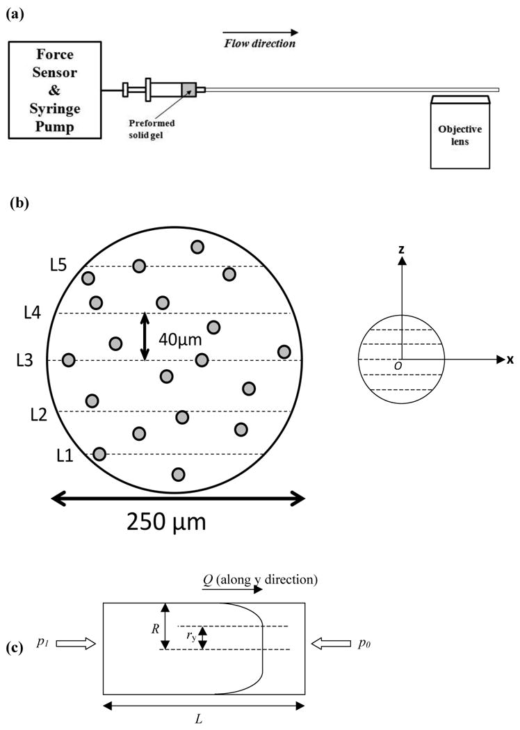
(a) Instrumental sketch of hydrogel flow measurement: The solid gel sample preformed in a syringe was flowed through the capillary flow cell at a constant flow rate controlled by a syringe pump. A force sensor was directly connected to measure the force applied on the syringe plunger during injection. Close to the end of the capillary, flow of gel was visualized under the confocal microscope through a 10× air lens by taking continuous frames of encapsulated fluorescent PS beads during flow. (b) Flow of beads was recorded at five respective horizontal layers (at constant z, with varying lateral coordinate x) along the z-direction across capillary diameter with a distance of 40 μm between each layer. The middle layer, L3, is the equator layer of the capillary. Temporal displacement of beads along the flow direction y (pointing into the paper) was averaged and recorded relative to the corresponding lateral coordinate x and vertical coordinate z. The origin was set at the center of the capillary cross-section. (c) Material flow profile within a capillary geometry (with a length of L and a radius of R) is used to determine yield stress, wall shear stress and shear rate at steady flow state. The sample flows to the right at a constant volumetric flow rate of Q and displays a plug flow behavior. The region of -ry < r < ry corresponds to the plug flow region (no deformation) while material within –R < r < -ry, ry < r < R is subject to shear deformation close to capillary wall. p1 is the pressure applied by syringe pump to keep the material flowing at a constant rate while p0 is the atmosphere (1.0×10⁵ Pa) at capillary outlet.
2.4 Hydrogel Flow Data Analysis
The flow behavior of the MAX8 β-hairpin peptide hydrogel was assessed by investigation of the flow of encapsulated fluorescent PS microspheres. One-dimensional flow velocity of these microspheres was determined by tracking each flowing bead in focus on one horizontal layer via the particle tracking software, Volocity (PerkinElmer). Specifically, two-dimensional coordinates of one focused bead were manually positioned between consecutive frames, giving rise to the distance one microsphere travelled between each frame and, thereby, providing an average flow velocity (Fig. 1b). Only beads that were in focus were saved to illustrate the hydrogel flow profile and these beads flowed along a straight path (path linearity of 99.99%).
Shear-thinning materials are usually observed to display plug flow behavior when their flow within a capillary reaches steady state60. Parameters including wall shear stress and gel yield stress were calculated from the corresponding flow profiles (Fig. 1c). The force exerted to drive the gel through the capillary, F1, equals the product of pressure drop, Δp, over the whole capillary and capillary inner cross-section area, πR2, where R is the capillary inner-radius, so,
| (1) |
Here, p1 is the pressure applied by the syringe pump to keep the gel material flowing at a constant volumetric flow rate against atmospheric pressure, p0, at the capillary outlet. The force is that measured by the force transducer. The shear force at the capillary wall that resists flow is given by
| (2) |
where σw is the wall shear stress and L is the capillary length.
At equilibrium, F1 should equal F2, which gives rise to
| (3) |
The gel yield stress σy can be calculated from the equation
| (4) |
in which ry is the radial width of the plug flow region. Note the shear stress depends linearly on the radial position from the center-line (r) that yields equation (4).
The apparent shear rate γ̇a is defined as
| (5) |
in which Q is the volumetric flow rate that is dictated by the syringe injection velocity and the bore diameter61.
2.5 Cell Culture Conditions, Cell Encapsulation and Live-dead Assay
MG63 (progenitor osteoblast cell line from rat osteosarcoma) cells were cultured in complete cell culture medium (stock 1× DMEM with addition of 10 vol% FBS and 50 μl·mL-1 Penicilin-Streptomycin). For cell encapsulation studies, trypsin-EDTA was used to dissociate adherent cells from tissue culture flasks. The detached cells were then counted and suspended in 1× DMEM with 25mM HEPES at a concentration of 5×10⁶ cells·mL-1. 300 μL of the cell suspension was added to an equal volume of 1 wt% or 1.5 wt% MAX8 peptide solution buffered to pH 7.4 with 25 mM HEPES. To address effects of shear-thin injection on encapsulated cell payloads, the cell/gel construct was quickly transferred into a 1 mL syringe, allowed to undergo gelation in a humidified incubator (37 °C, 5% CO2) for 40 min and then shear-thin delivered via a 20 cm-long, 250 μm-ID borosilicate capillary into an 8-well coverslip bottom borosilicate confocal chamber (Nalge Nunc, Naperville, IL) at constant rate controlled by a syringe pump. Subsequently, 400 μL of complete cell culture medium was added to the top of the injected gel with encapsulated cells and was incubated for three hours. The cell culture medium was removed after three hours and 400 μL complete cell culture medium supplemented with 2 mM of calcein acetoxymethylester (calcein AM, cytoplasmic dye) and 5 mM of propidium iodide (PI, nuclear stain) was added. Live-dead assay were performed on a Zeiss LSM 510 NLO in order to assess the effect of shear-thin delivery on cell viability. We used 488 nm excitation with a 500-550 nm band pass emission filter and 543 nm excitation with a 560 nm long pass long pass filter) to image calcein AM and PI, respectively. The encapsulated cells were imaged within successive optical slices of 19.6 μm thickness in the material. For comparison, the cell/gel constructs were directly transferred to the borosilicate confocal chamber after mixing the cell suspension and buffered peptide solution that was incubated for 3hrs and then imaged using the live-dead cell assay.
2.6 Flow Measurement of Encapsulated Cell Payloads within Hydrogel
MG63 cells were dissociated from tissue culture flasks with Trypsin-EDTA, counted and suspended in complete cell culture medium supplemented with 2 mM of calcein AM. The cell suspension was then incubated for 10 min, centrifuged and resuspended in 1× DMEM with 25mM HEPES at a concentration of 5×10⁶ cells·mL-1. 300 μL of the cell suspension was added to an equal volume of 1 wt% or 1.5 wt% MAX8 peptide solution buffered to pH 7.4 with 25 mM HEPES. The cell/gel construct was quickly transferred into a 1 mL syringe, allowed to undergo gelation in a humidified incubator (37 °C, 5% CO2) for 30 min and then shear-thin injected through the capillary flow cell at constant rate controlled by the syringe pump. Flow of encapsulated MG63 cells was observed and analyzed under the same conditions that were adopted to investigate hydrogel flow behavior with (488 nm excitation and 495-555 nm band pass emission filter was used to image calcein AM labeled cells. It should be noted that, similar to the addition of beads to the peptide hydrogel, the amount of MG63 cells added did not affect the bulk hydrogel stiffness or rheological properties (please see Fig. SI-3).
3. Results and discussion
3.1 Hydrogel Behavior during Injection Flow
The effects of injection shear on hydrogel structure were quantitatively assessed by investigating the hydrogel flow behavior in a capillary geometry mimicking a syringe needle that is used in actual therapeutic injection delivery. Previously, minimal fibril alignment and identical network nanostructure were observed via small angle x-ray scattering measurements for MAX8 gels at rest and flowing at 10 μL/min within a 1.5 mm-ID capillary20. In the current work, hydrogel flow behavior was investigated under higher flow rates within a much thinner, 250 μm-ID capillary in order to mimic the injection flow condition within a 26-gauge needle. Hydrogelation of a buffered MAX8 peptide solution was initiated within a syringe to make a solid with an average storage modulus for 0.5wt% MAX8 and 0.75wt% MAX8 (pH 7.4, 25 mM HEPES, DMEM cell culture medium) equal to 560 ± 50 Pa and 1050 ± 80 Pa, respectively (Fig. 2 and Fig. SI-1), based on 3 independent samples (for each peptide concentration studied). Therefore, equilibrated gels of the same peptide concentration preformed in 1 mL syringes were of uniform and known rigidity prior to capillary flow experiments. The preformed gel was then injected into the 250 μm-ID capillary flow cell at a constant volumetric flow rate controlled by a syringe pump. Close to the end of the capillary, hydrogel flow behavior was visualized by tracking flowing PS microspheres at five respective horizontal layers at two intervals of 40 μm above and below the center-line.
Fig. 2.
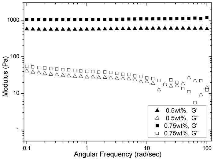
Dynamic frequency sweep of two individual MAX8 hydrogels: 0.5wt% and 0.75 wt% at pH7.4, 25mM HEPES, 37°C.
To investigate the effect of flow rate on hydrogel flow behavior, three 0.5 wt% MAX8 gels preformed in syringes were individually subjected to a constant volumetric flow rate of 4.00, 6.00, 8.00 mL/hr. Fig. 3 and Fig. SI-4, 5 display the corresponding gel velocity profile at all five horizontal layers (the central layer intersects the capillary cross-section) and each data point represents the one-dimensional average flow velocity of one PS microsphere tracked. For each flow rate, the velocity profile is similar at all layers investigated. There is a wide plug flow zone in the middle within which the gel sample flows with one velocity, and there is a shear zone at both sides close to the capillary wall where the velocity dramatically falls. It should be noted that the average flow velocity, the quotient of the volumetric flow rate divided by capillary cross-sectional area, is essentially equal to the central plug velocity, indicating that the entire gel sample flowed at a uniform rate with the exception of the zone near the wall. Since there is little velocity difference between the radial positions in the plug zone, there is minimal shear rate that the gel experienced in the plug zone since shear rate is defined as the velocity gradient within a flowing material60. Only gel within the small shear zone close to the capillary wall experienced some magnitude of shear rate and, therefore, deformation since the flow velocity was slower when it was closer to capillary wall. Therefore, cells encapsulated in a gel will not experience shear in the plug flow but will experience a shear stress up to values equal to the yield stress. Calculation of the yield stress from the velocity profile is discussed below.
Fig. 3.
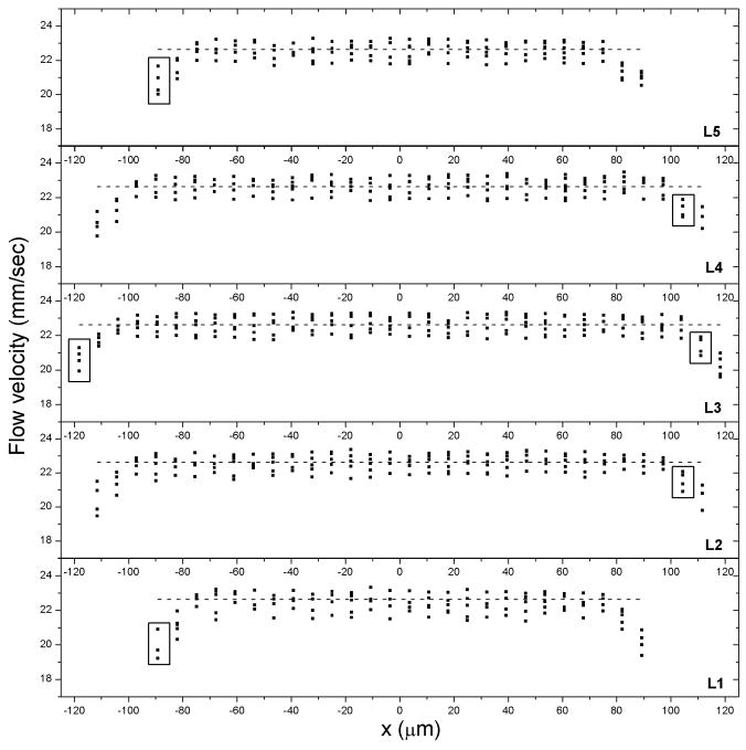
Flow profile at five respective horizontal layers: one-dimensional flow velocity plotted against lateral position when a 0.5wt% MAX8 gel (pH7.4, 25mM HEPES, 37°C) was flowing at a constant volumetric flow rate of 4.00 mL/hr. The dash line denotes the average flow velocity. As denoted by boxes on the left side of the plot, particles that flowed within different layers (e.g. layer 5 at x = -89 μm, z = 80 μm as well as layer 1 at x = -89 μm, z = -80 μm) had flow velocity very close in value to those that flowed along the central layer 3 at x = -118 μm, z = 0 μm since the particles were located at the same radial distance from the capillary center. Similarly in boxes on the right hand side of the plot, the same flow velocity was also observed from layer 4 at x = 104 μm, z = 40 μm and layer 2 at x = 104 μm, z = -40 μm as compared to the central layer 3 at position x = 111 μm, z = 0 μm since all three positions were located at the same radial position relative to the center of the capillary.
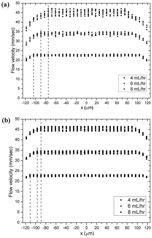
This is an exciting velocity profile for injectable therapeutic delivery since the gel material and encapsulated therapeutic payloads within the plug flow region will experience little shear rate. Only the gel and payload near the wall will experience a velocity gradient. Fig. 4a shows that the diameter of the plug flow region is dependent on the flow rate applied. For the three 0.5 wt% MAX8 gels individually flowing at 4.00 mL/hr, 6.00 mL/hr, and 8.00 mL/hr the corresponding plug flow region width of the central layer is 104 μm, 89 μm, and 75 μm. The corresponding plug velocities are 22.6±0.8 mm/sec, 33.9±1.7 mm/sec and 45.3±2.7 mm/sec for the lowest to highest flow rates. These results altogether indicate that range of the shear zone near the wall (denoted by the dashed lines) is wider for higher flow rates. As discussed below the central plug diameter is dictated by the yield stress and shear stress at the wall. Besides, it was observed that values of particle flow velocity were almost the same for different (x, z) coordinates but with same radial distance from the origin (Fig. 3 and Fig. SI-4, 5), indicating that flow of gel material is uniform for identical radial position r. Flow behavior of 0.75 wt% MAX8 gels through the 250 μm-ID capillary flow cell was also investigated under the same flow conditions as the 0.5 wt% MAX8 gels. Although 0.75 wt% MAX8 hydrogels (average G′ of 1050 Pa, Fig. SI-1) are stiffer than 0.5 wt% MAX8 hydrogels (average G′ of 560 Pa, Fig. SI-1) due to higher peptide concentration39,42, the flow profiles of all the gel samples studied displayed similar characteristics of plug flow (Fig. SI-6, 7, 8). Once again, the mean flow velocity lies near the middle of the data points within the plug flow region, indicative of the uniform gel velocity. Like the 0.5 wt% gels, flow behavior of 0.75 wt% gels is dependent on flow rate. Fig. 4b indicates that for the three 0.75 wt% MAX8 gels flowed at 4.00 mL/hr, 6.00 mL/hr, or 8.00 mL/hr, respectively, the corresponding plug flow region of the central layer of the capillary has a width of 110 μm, 96 μm, and 89 μm, respectively. The plug velocity is 22.6±0.6 mm/sec, 33.9±1.1 mm/sec, and 45.3±1.6 mm/sec, for lowest to highest flow rate. By comparing results plotted in Fig. 4a and 4b, it was also found that pre-shear gel stiffness had an impact on gel flow behavior. The central plug diameter depends on the yield stress and shear stress at the wall via, ry=(σy/σw)·R. Thus, hydrogels allow one to tailor the plug diameter through peptide concentration. It is clear that the higher concentration gel has a bigger plug zone that is dictated by the yield stress.
Fig. 4.
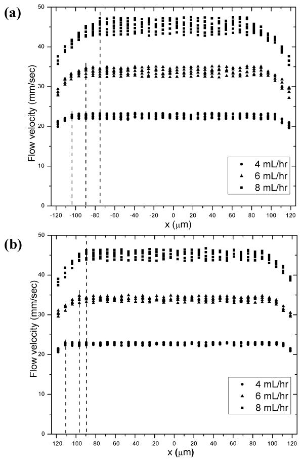
Flow profile at the center horizontal layer, L3: one-dimensional flow velocity plotted against lateral position for three individual (a) 0.5wt% MAX8 gels (pH7.4, 25mM HEPES, 37°C) (b) 0.75wt% MAX8 gels (pH7.4, 25mM HEPES, 37°C) at a constant volumetric flow rate of 4.00, 6.00, 8.00 mL/hr, respectively.
The yield stress, or yield point, is usually defined as the critical shear stress below which the material is a static solid and above which the material starts to flow60. This is an important parameter to address for injectable biomaterials since it is directly related to a measure of the injected hydrogel material stability. The yield stress, σy, can be calculated from σy = (Δp·ry)/2L, in which Δp is the pressure drop between two ends of the capillary flow cell, ry the width of plug flow region, and L the capillary length61. Also, the wall shear stress and apparent shear rate were calculated according to equations (3) and (5), respectively. In Table 1, values of Δp, ry, σy, σw and γ̇a are listed for 0.5 wt% and 0.75 wt% gels under flow rates of 4.00 mL/hr, 6.00 mL/hr, and 8.00 mL/hr. For each flow rate, three identical gel samples were examined. For each gel sample ten readings were recorded and averaged to get the pressure drop in the form of Δpx = ΔPx ± eΔpx. The value of Δp listed in Table 1 takes the average of all three samples studied, which is Δp = (ΔP1+ΔP2+ΔP3)/3. The uncertainty of the pressure drop, eΔpx, was considered the standard deviation of ΔP1, ΔP2 and ΔP3 from Δp. Despite the difference in flow rates, one finds the capillary flow measurements gave consistent values of yield stress as they should, which were 228±3 Pa for 0.5 wt% MAX8 gels and 372±4 Pa for 0.75 wt% gels.
Table 1.
pressure drop across the capillary, Δp, plug flow region width, ry, yield stress, σy, wall shear stress, σw, and apparent shear rate, γ̇a, for 0.5 wt% and 0.75 wt% MAX8 hydrogels (pH 7.4, 25 mM HEPES, 37 °C) under various flow rates.
| Flow rate | 0.5wt% MAX8 gel | ||||
|---|---|---|---|---|---|
| Δp | ry | σy | σw | γ̇a | |
| 4.00 mL/hr | (8.7±0.1)×105 Pa | 104 μm | 226±3 Pa | 272±3 Pa | 720/s |
| 6.00 mL/hr | (10.4±0.2)×105 Pa | 89 μm | 231±4Pa | 325±6 Pa | 1090/s |
| 8.00 mL/hr | (12.1±0.3)×105 Pa | 75 μm | 227±6 Pa | 378±9 Pa | 1450/s |
| Flow rate | 0.75wt% MAX8 gel | ||||
| Δp | ry | σy | σw | γ̇a | |
| 4.00 mL/hr | (13.5±0.3)×105 Pa | 110 μm | 371±8Pa | 422±9 Pa | 720/s |
| 6.00 mL/hr | (15.4±0.4)×105 Pa | 96 μm | 370±10Pa | 481±12 Pa | 1090/s |
| 8.00 mL/hr | (16.9±0.5)×105 Pa | 89 μm | 376±11Pa | 528±16Pa | 1450/s |
3.2 Live–dead Assay of Encapsulated Cells after Capillary Injection
We have demonstrated the effect of shear-thin delivery on hydrogel flow behavior by varying the flow rate and gel stiffness. In order to further examine if a β-hairpin hydrogel can effectively serve as a carrier material for future applications of injectable cell therapies, it is also essential to investigate the behavior of cells encapsulated in hydrogel during and after injection. MG63 (progenitor osteoblast cell line from rat osteosarcoma) cells were cultured in vitro. These cells usually display an extended morphology when they are alive and adherent to the surface of a MAX8 hydrogel or tissue culture plate (Fig. SI-9). For cell encapsulation, the addition of MG63 cells suspended in cell culture medium to buffered MAX8 peptide solution gave rise to quick formation of a solid MAX8 gel, kinetically trapping the cells through homogeneous cell encapsulation.19,20 MG63 cells homogeneously encapsulated in individual 0.5 wt% or 0.75 wt% MAX8 hydrogels in vitro were injected into wells of borosilicate confocal chambers through the 250 μm-ID, 20cm long capillary flow cell at 4.00 mL/hr, 6.00 mL/hr or 8.00 mL/hr, respectively. After incubating these cell/gel constructs for three hours post injection, a live-dead assay was then performed by staining living cells green with calcein acetoxymethylester and dead cells red with propidium iodide in order to image effects of capillary injection on cell viability. As examined under the confocal microscope, a vast majority of the encapsulated cells remained alive and evenly distributed within the hydrogel scaffold after capillary injection at different gel rigidity and flow rate (Fig. 5a-c and 6 a-c), demonstrating that injection through the 20cm long capillary flow cell caused minimal cell death. In our previous work, we presented the gel recovery kinetics measured rheologically over time. Right after the same MAX8 hydrogel was injected onto the rheometer via a 26-gauge needle (with same inner-diameter as the capillary tube), the gel was immediately a solid and the original gel stiffness prior to injection was almost restored after two hours. Hence, the immediate post-injection solidification of gel and quick restoration of gel stiffness over time enable even spatial cell distribution19,20 as observed prior to injection (Fig. 5d). These observations were consistent with results of live-dead assay performed on C3H10t1/2 mesenchymal stem cells that were encapsulated in the same hydrogel and injected from a 20-gauge syringe needle.19
Fig. 5.
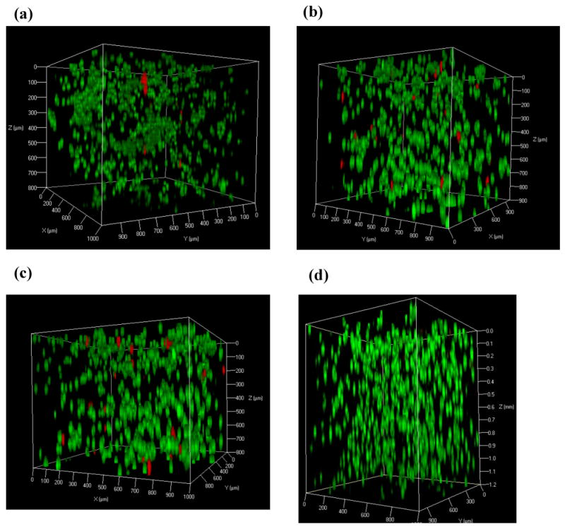
Three-dimensional confocal microscope images showing live-dead assays of MG63 cells encapsulated in 0.5 wt% MAX8 hydrogel at a concentration of 5×10⁶ cells/mL. These images were taken three hours after three individual gel-cell constructs were shear-thin delivered via the 250 μm-ID, 20cm long capillary flow cell at (a) 4.00 mL/hr (b) 6.00 mL/hr (c) 8.00 mL/hr. For comparison, live-dead assay was also performed on MG63 cells (d) three hours after in situ encapsulation in 0.5 wt% MAX8 hydrogel. Dead cells (red) and live cells (green).
Fig. 6.
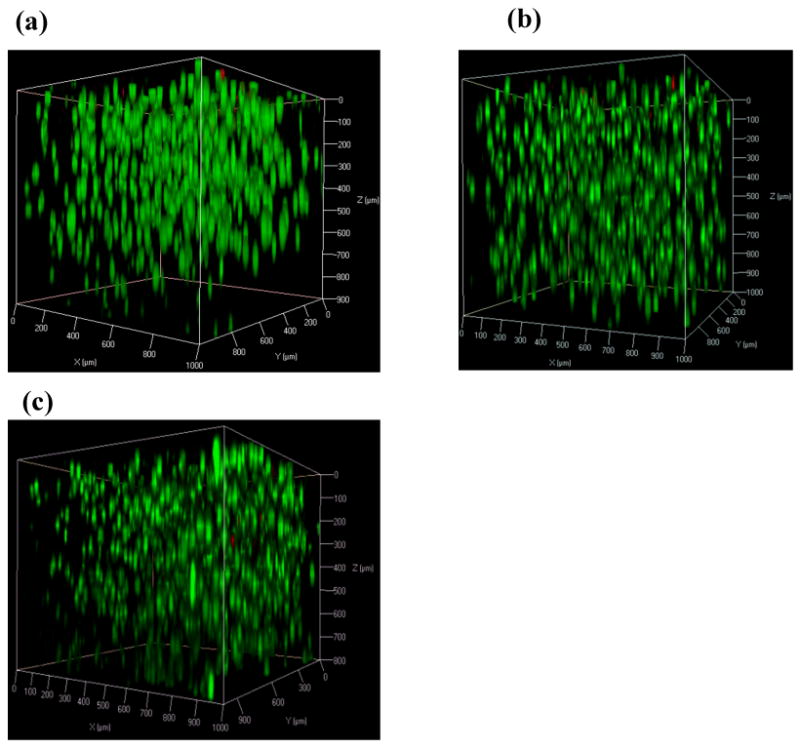
Three-dimensional confocal microscope (LSCM) images showing live–dead assays of MG63 cells encapsulated in 0.75 wt% MAX8 hydrogel at a concentration of 5×10⁶ cells/mL. These images were taken three hours after three individual gel-cell constructs were shear-thin delivered via the 250 μm-ID, 20cm long capillary flow cell at (a) 4.00 mL/hr (b) 6.00 mL/hr (c) 8.00 mL/hr. Dead cells (red) and live cells (green).
3.3 Flow Behavior of Encapsulated Cells during Injection Flow
The effect of injection shear on encapsulated cell payloads was quantitatively assessed by investigating flow behavior of encapsulated MG63 cells when individual cell/gel constructs flowed through the 250 μm-ID capillary flow cell at a constant volumetric flow rate. The living MG63 cells were stained green by calcein acetoxymethylester prior to 3D-encapsulation in order for cell visualization under confocal microscopy. These labeled cells were then homogeneously encapsulated in MAX8 gels, incubated for one hour and then put through the capillary flow cell. Three 0.5wt% MAX8 hydrogels encapsulating living MG63 cells were individually subject to steady flow of 4.00 mL/hr, 6.00 mL/hr and 8.00 mL/hr.
Fig. SI-10, 11, 12 show the corresponding velocity profiles at all five horizontal layers investigated: there is a central wide plug flow region where gel material and cell payloads experienced little, if no, shear and a narrow shear zone close to capillary wall where gel and cells were subject to shear deformation. Fig. 7a shows that the diameter of the plug flow region for the three cell/gel constructs at volumetric flow rates of 4.00, 6.00, 8.00 mL/hr were essentially the same as that of the MAX8 gel samples discussed earlier. These observations validate that the plug flow behavior of both hydrogel and encapsulated cell payloads is promising for encapsulated cell delivery since the cells within the plug flow region experienced minimal shear rate and that the rheological properties are not dependent on the encapsulated cells.
Fig. 7.
Flow profile at the center horizontal layer, L3: one-dimensional cell flow velocity plotted against lateral position for three individual cell/gel constructs (a) MG 63 cells encapsulated in 0.5wt% MAX8 gels (pH7.4, 25mM HEPES, 37°C) and (b) MG 63 cells encapsulated in 0.75wt% MAX8 gels (pH7.4, 25mM HEPES, 37°C) at 4.00, 6.00, 8.00 mL/hr, respectively.
The flow behavior of cells encapsulated in 0.75 wt% gels (Fig. SI-13, 14, 15) was also found dependent on flow rate. Fig. 7b shows that for the three 0.75 wt% MAX8 at flow rates of 4.00 mL/hr, 6.00 mL/hr, 8.00 mL/hr, the diameter of the corresponding plug flow region was essentially that of MAX8 gel samples. By comparing results plotted in both Fig. 7a and 7b, it was also found that peptide concentration had an impact on cell flow behavior. For same flow rate, the flow profile of cell payloads in a 0.75 wt% gel sample has narrower shear zones than those of cells encapsulated in a 0.5 wt% gel in agreement with the results discussed above. Thus, a higher concentration gel will yield a larger central plug diameter to shield more cells from a velocity gradient.
We also studied flow behavior of living MG63 cells suspended in buffered cell culture media in order to compare the shear conditions that cells experience when injected in media solution as opposed to when encapsulated in a hydrogel carrier. Fig. 8 displays the corresponding flow profile; when the carrier material is a buffer solution, cells across the entire diameter obviously were subject to a velocity gradient, and consequent shear, during injection flow. In contrast, cells encapsulated within MAX8 gel only experienced shear deformation within the narrow shear zones close to capillary walls demonstrating that the β-hairpin hydrogels effectively protected cell payloads from shear during shear-thin delivery as a carrier material. Minimal cell death was observed in both cases while improved cell viability after syringe injection was observed for stem cells encapsulated in alginate hydrogels17 and for CHO K1 cells encapsulated in telechelic protein hydrogels16. Future studies will clarify if this is due to different phenotype and will determine more specific cell biology effects of shear on gel-encapsulated vs unencapsulated cells after injection.
Fig. 8.
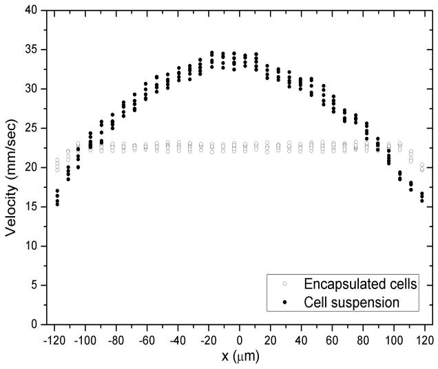
Flow profile at 4.00 mL/hr at the center horizontal layer, L3. Solid symbols: one-dimensional flow velocity of living MG 63 cells against lateral position when suspended in aqueous buffer (pH7.4, 25mM HEPES, 37°C). Open symbols: one-dimensional flow velocity of living MG 63 cells when encapsulated in 0.75wt% MAX8 gels, pH7.4, 25mM HEPES, 37°C).
4. Conclusion
β-hairpin peptide hydrogel structure and rheological behavior during flow that mimics the actual situation of syringe injection was studied. All β-hairpin hydrogels considered undergo plug flow when forced through a 250 μm-ID capillary. Only the gel material directly at the wall of the capillary experiences a velocity gradient while the gel material within the remainder of the capillary flows in plug flow fashion and is therefore subject to minimal or no shear rate. Capillary flow experiments also indicated that the width of the central gel plug region was wider and velocity was more homogeneous in gels that experienced lower flow rate or had higher stiffness. This is similar to what is observed for some colloidal material systems that yield and flow under shear stress that is above the material yield stress.55,62-68 This velocity profile is promising for cellular delivery since all material and encapsulated cells within the plug flow experience little or no velocity gradient. In contrast, the velocity profile of cells suspended in buffer solution is laminar, indicating that cells within the entire profile experience a velocity gradient. This comparison demonstrates that β-hairpin hydrogels physically protected cell payloads within plug flow from a velocity gradient induced by injection flow that may be critical to some cells that can exhibit biological alterations after undergoing shear. As previously mentioned, the injection of a solid material that immediately reheals after shear-thin injection guarantees that the encapsulated payload will stay localized to the area of injection and exhibit properties present in the material prior to injection. Furthermore, live-dead assays demonstrated that shear-thin delivery from capillary injection had no obvious impact on the viability of encapsulated cells or cell spatial distribution. The major novelty of this work is movement towards clinical relevance. We were able to quantify effects of shear-thin injection delivery on hydrogel flow behavior and encapsulated cell payloads in a cylindrical capillary geometry that mimicked the actual situation of injection through a syringe needle. Although future experiments and ongoing work will be performed to assess higher order biological effects of shear-thin delivery on cell fate (e.g. gene expression, phenotype) as well as in vivo effects of cell-gel constructs on surrounding tissue and immunological response, observations in this work suggest that β-hairpin peptide hydrogels are excellent candidates for injectable therapeutic delivery vehicles due to their shear-thin flow and immediate recovery properties.
Supplementary Material
Acknowledgments
This work was supported by National Institutes of Health (NIH) through grant 5P20RR017716-07 and grant R01 DE016386-01 and National Institute of Standards and Technology (NIST) through the UD-NIST Center of Neutron Science under grant number DOC #70NANB7H6178. The statements, findings, conclusions, and recommendations are those of the authors and do not necessarily reflect the views of NIH or NIST. Support from the Delaware Biotechnology Institute Bioimaging Center is acknowledged and we especially would like to thank Dr. Jeffery Caplan for his help with confocal microscope experiments. We thank Derrick Allen at University of Delaware Machine Shop for his help with fabrication of the confocal microscope stage, and Doug Nixon at University of Delaware Glass Shop for his help with fabrication of the glass capillaries. And we sincerely appreciate invaluable discussions with and insightful advice from Professor Norman J. Wagner and Dr. Steven Hudson.
Footnotes
Supporting Information Available: Linear viscoelastic properties of hydrogels (without and with polystyrene beads or MG63 cells), flow profiles of gels and cells at five respective horizontal layers, and live-dead assay of 2D-cultured MG 63 cells. This information is available free of charge via the Internet at http://pubs.acs.org/.
References
- 1.Slaughter BV, Khurshid SS, Fisher OZ, Khademhosseini A, Peppas NA. Hydrogels in Regenerative Medicine. Adv Mater. 2009;21:3307–3329. doi: 10.1002/adma.200802106. [DOI] [PMC free article] [PubMed] [Google Scholar]
- 2.Tous E, Purcell B, Ifkovits J, Burdick J. Injectable Acellular Hydrogels for Cardiac Repair. J Cardiovasc Transl Res. 2011;4:528–542. doi: 10.1007/s12265-011-9291-1. [DOI] [PubMed] [Google Scholar]
- 3.Borselli C, Storrie H, Benesch-Lee F, Shvartsman D, Cezar C, Lichtman JW, Vandenburgh HH, Mooney DJ. Functional muscle regeneration with combined delivery of angiogenesis and myogenesis factors. Proc Natl Acad Sci USA. 2010;107:3287–3292. doi: 10.1073/pnas.0903875106. [DOI] [PMC free article] [PubMed] [Google Scholar]
- 4.McCall JD, Lin CC, Anseth KS. Affinity peptides protect transforming growth factor beta during encapsulation in poly(ethylene glycol) hydrogels. Biomacromolecules. 2011;12:1051–1057. doi: 10.1021/bm101379v. [DOI] [PMC free article] [PubMed] [Google Scholar]
- 5.Vulic K, Shoichet MS. Tunable Growth Factor Delivery from Injectable Hydrogels for Tissue Engineering. J Am Chem Soc. 2011;134:882–885. doi: 10.1021/ja210638x. [DOI] [PMC free article] [PubMed] [Google Scholar]
- 6.Hudson SP, Langer R, Fink GR, Kohane DS. Injectable in situ cross-linking hydrogels for local antifungal therapy. Biomaterials. 2010;31:1444–1452. doi: 10.1016/j.biomaterials.2009.11.016. [DOI] [PMC free article] [PubMed] [Google Scholar]
- 7.Sivakumaran D, Maitland D, Hoare T. Injectable microgel-hydrogel composites for prolonged small-molecule drug delivery. Biomacromolecules. 2011;12:4112–4120. doi: 10.1021/bm201170h. [DOI] [PubMed] [Google Scholar]
- 8.Branco MC, Pochan DJ, Wagner NJ, Schneider JP. Macromolecular diffusion and release from self-assembled beta-hairpin peptide hydrogels. Biomaterials. 2009;30:1339–1347. doi: 10.1016/j.biomaterials.2008.11.019. [DOI] [PMC free article] [PubMed] [Google Scholar]
- 9.Altunbas A, Lee SJ, Rajasekaran SA, Schneider JP, Pochan DJ. Encapsulation of curcumin in self-assembling peptide hydrogels as injectable drug delivery vehicles. Biomaterials. 2011;32:5906–5914. doi: 10.1016/j.biomaterials.2011.04.069. [DOI] [PMC free article] [PubMed] [Google Scholar]
- 10.Bakota EL, Wang Y, Danesh FR, Hartgerink JD. Injectable Peptide Nanofiber Hydrogel as Delivery Agent for Stem Cell Secretome. Biomacromolecules. 2011;12:1651–1657. doi: 10.1021/bm200035r. [DOI] [PMC free article] [PubMed] [Google Scholar]
- 11.Aimetti AA, Machen AJ, Anseth KS. Poly(ethylene glycol) hydrogels formed by thiol-ene photopolymerization for enzyme-responsive protein delivery. Biomaterials. 2009;30:6048–6054. doi: 10.1016/j.biomaterials.2009.07.043. [DOI] [PMC free article] [PubMed] [Google Scholar]
- 12.Branco MC, Pochan DJ, Wagner NJ, Schneider JP. The effect of protein structure on their controlled release from an injectable peptide hydrogel. Biomaterials. 2010;31:9527–9534. doi: 10.1016/j.biomaterials.2010.08.047. [DOI] [PMC free article] [PubMed] [Google Scholar]
- 13.Godier-Furnémont AFG, Martens TP, Koeckert MS, Wan L, Parks J, Arai K, Zhang G, Hudson B, Homma S, Vunjak-Novakovic G. Composite scaffold provides a cell delivery platform for cardiovascular repair. Proc Natl Acad Sci USA. 2011;108:7974–7979. doi: 10.1073/pnas.1104619108. [DOI] [PMC free article] [PubMed] [Google Scholar]
- 14.Kloxin AM, Kasko AM, Salinas CN, Anseth KS. Photodegradable hydrogels for dynamic tuning of physical and chemical properties. Science. 2009;324:59–63. doi: 10.1126/science.1169494. [DOI] [PMC free article] [PubMed] [Google Scholar]
- 15.Su J, Hu BH, Lowe WL, Jr, Kaufman DB, Messersmith PB. Anti-Inflammatory Peptide-Functionalized Hydrogels for Insulin-secreting Encapsulation. Biomaterials. 2010;31:308–314. doi: 10.1016/j.biomaterials.2009.09.045. [DOI] [PMC free article] [PubMed] [Google Scholar]
- 16.Olsen BD, Kornfield JA, Tirrell DA. Yielding Behavior in Injectable Hydrogels from Telechelic Proteins. Macromolecules. 2010;43:9094–9099. doi: 10.1021/ma101434a. [DOI] [PMC free article] [PubMed] [Google Scholar]
- 17.Aguado BA, Mulyasasmita W, Su J, Lampe KJ, Heilshorn SC. Improving Viability of Stem Cells During Syringe Needle Flow Through the Design of Hydrogel Cell Carriers. Tissue Eng Part A. 2011 doi: 10.1089/ten.tea.2011.0391. in press. [DOI] [PMC free article] [PubMed] [Google Scholar]
- 18.Lu HD, Charati MB, Kim IL, Burdick JA. Injectable Shear-Thinning Hydrogels Engineered with a Self-Assembling Dock-and-Lock Mechanism. Biomaterials. 2012;33:2145–2153. doi: 10.1016/j.biomaterials.2011.11.076. [DOI] [PubMed] [Google Scholar]
- 19.Haines-Butterick L, Rajagopal K, Branco M, Salick D, Rughani R, Pilarz M, Lamm MS, Pochan DJ, Schneider JP. Controlling hydrogelation kinetics by peptide design for three-dimensional encapsulation and injectable delivery of cells. Proc Natl Acad Sci USA. 2007;104:7791–7796. doi: 10.1073/pnas.0701980104. [DOI] [PMC free article] [PubMed] [Google Scholar]
- 20.Yan C, Altunbas A, Yucel T, Nagarkar RP, Schneider JP, Pochan DJ. Injectable solid hydrogel: mechanism of shear-thinning and immediate recovery of injectable β-hairpin peptide hydrogels. Soft Matter. 2010;6:5143–5156. doi: 10.1039/C0SM00642D. [DOI] [PMC free article] [PubMed] [Google Scholar]
- 21.Ma Z, Nelson DM, Hong Y, Wagner WR. Thermally responsive injectable hydrogel incorporating methacrylate-polylactide for hydrolytic lability. Biomacromolecules. 2010;11:1873–1881. doi: 10.1021/bm1004299. [DOI] [PMC free article] [PubMed] [Google Scholar]
- 22.Yokoi H, Kinoshita T, Zhang SG. Dynamic reassembly of peptide RADA16 nanofiber scaffold. Proc Natl Acad Sci USA. 2005;102:8414–8419. doi: 10.1073/pnas.0407843102. [DOI] [PMC free article] [PubMed] [Google Scholar]
- 23.Mosiewicz KA, Johnsson K, Lutolf MP. Phosphopantetheinyl transferase-catalyzed formation of bioactive hydrogels for tissue engineering. J Am Chem Soc. 2010;132:5972–5974. doi: 10.1021/ja9098164. [DOI] [PubMed] [Google Scholar]
- 24.Thornton K, Smith AM, Merry CLR, Ulijn RV. Controlling stiffness in nanostructured hydrogels produced by enzymatic dephosphorylation. Biochem Soc Trans. 2009;37:660–664. doi: 10.1042/BST0370660. [DOI] [PubMed] [Google Scholar]
- 25.Reza AT, Nicoll SB. Characterization of novel photocrosslinked carboxymethylcellulose hydrogels for encapsulation of nucleus pulposus cells. Acta Biomater. 2010;6:179–186. doi: 10.1016/j.actbio.2009.06.004. [DOI] [PubMed] [Google Scholar]
- 26.Kretlow JD, Klouda L, Mikos AG. Injectable matrices and scaffolds for drug delivery in tissue engineering. Adv Drug Del Rev. 2007;59:263–273. doi: 10.1016/j.addr.2007.03.013. [DOI] [PubMed] [Google Scholar]
- 27.Sharma B, Williams CG, Khan M, Manson P, Elisseeff JH. In vivo chondrogenesis of mesenchymal stem cells in a photopolymerized hydrogel. Plast Reconstr Surg. 2007;119:112–120. doi: 10.1097/01.prs.0000236896.22479.52. [DOI] [PubMed] [Google Scholar]
- 28.Ramachandran S, Tseng Y, Yu YB. Repeated Rapid Shear-Responsiveness of Peptide Hydrogels with Tunable Shear Modulus. Biomacromolecules. 2005;6:1316–1321. doi: 10.1021/bm049284w. [DOI] [PMC free article] [PubMed] [Google Scholar]
- 29.Aulisa L, Dong H, Hartgerink JD. Self-Assembly of Multidomain Peptides: Sequence Variation Allows Control over Cross-Linking and Viscoelasticity. Biomacromolecules. 2009;10:2694–2698. doi: 10.1021/bm900634x. [DOI] [PubMed] [Google Scholar]
- 30.Schneider JP, Pochan DJ, Ozbas B, Rajagopal K, Pakstis L, Kretsinger J. Responsive hydrogels from the intramolecular folding and self-assembly of a designed peptide. J Am Chem Soc. 2002;124:15030–15037. doi: 10.1021/ja027993g. [DOI] [PubMed] [Google Scholar]
- 31.Ozbas B, Kretsinger J, Rajagopal K, Schneider JP, Pochan DJ. Salt-triggered peptide folding and consequent self-assembly into hydrogels with tunable modulus. Macromolecules. 2004;37:7331–7337. [Google Scholar]
- 32.Yan C, Pochan DJ. Rheological properties of peptide-based hydrogels for biomedical and other applications. Chem Soc Rev. 2010;39:3528–3540. doi: 10.1039/b919449p. [DOI] [PMC free article] [PubMed] [Google Scholar]
- 33.Pochan DJ, Schneider JP, Kretsinger J, Ozbas B, Rajagopal K, Haines L. Thermally reversible hydrogels via intramolecular folding and consequent self-assembly of a de Novo designed peptide. J Am Chem Soc. 2003;125:11802–11803. doi: 10.1021/ja0353154. [DOI] [PubMed] [Google Scholar]
- 34.Haines LA, Rajagopal K, Ozbas B, Salick DA, Pochan DJ, Schneider JP. Light-activated hydrogel formation via the triggered folding and self-assembly of a designed peptide. J Am Chem Soc. 2005;127:17025–17029. doi: 10.1021/ja054719o. [DOI] [PMC free article] [PubMed] [Google Scholar]
- 35.Rajagopal K, Ozbas B, Pochan DJ, Schneider JP. Probing the importance of lateral hydrophobic association in self-assembling peptide hydrogelators. Eur Biophys J. 2006;35:162–169. doi: 10.1007/s00249-005-0017-7. [DOI] [PubMed] [Google Scholar]
- 36.Salick DA, Pochan DJ, Schneider JP. Design of an Injectable beta-Hairpin Peptide Hydrogel That Kills Methicillin-Resistant Staphylococcus aureus. Adv Mater. 2009;21:4120–4123. [Google Scholar]
- 37.Rajagopal K, Lamm MS, Haines-Butterick LA, Pochan DJ, Schneider JP. Tuning the pH Responsiveness of beta-Hairpin Peptide Folding, Self-Assembly, and Hydrogel Material Formation. Biomacromolecules. 2009;10:2619–2625. doi: 10.1021/bm900544e. [DOI] [PubMed] [Google Scholar]
- 38.Rughani RV, Salick DA, Lamm MS, Yucel T, Pochan DJ, Schneider JP. Folding, Self-Assembly, and Bulk Material Properties of a De Novo Designed Three-Stranded beta-Sheet Hydrogel. Biomacromolecules. 2009;10:1295–1304. doi: 10.1021/bm900113z. [DOI] [PubMed] [Google Scholar]
- 39.Hule RA, Nagarkar RP, Altunbas A, Ramay HR, Branco MC, Schneider JP, Pochan DJ. Correlations between structure, material properties and bioproperties in self-assembled beta-hairpin peptide hydrogels. Faraday Discuss. 2008;139:251–264. doi: 10.1039/b717616c. [DOI] [PMC free article] [PubMed] [Google Scholar]
- 40.Kretsinger JK, Haines LA, Ozbas B, Pochan DJ, Schneider JP. Cytocompatibility of self-assembled β-hairpin peptide hydrogel surfaces. Biomaterials. 2005;26:5177–5186. doi: 10.1016/j.biomaterials.2005.01.029. [DOI] [PubMed] [Google Scholar]
- 41.Haines-Butterick LA, Salick DA, Pochan DJ, Schneider JP. In vitro assessment of the pro-inflammatory potential of beta-hairpin peptide hydrogels. Biomaterials. 2008;29:4164–4169. doi: 10.1016/j.biomaterials.2008.07.009. [DOI] [PMC free article] [PubMed] [Google Scholar]
- 42.Ozbas B, Rajagopal K, Schneider JP, Pochan DJ. Semiflexible chain networks formed via self-assembly of beta-hairpin molecules. Phys Rev Lett. 2004;93:268106. doi: 10.1103/PhysRevLett.93.268106. [DOI] [PubMed] [Google Scholar]
- 43.Branco MC, Nettesheim F, Pochan DJ, Schneider JP, Wagner NJ. Fast Dynamics of Semiflexible Chain Networks of Self-Assembled Peptides. Biomacromolecules. 2009;10:1374–1380. doi: 10.1021/bm801396e. [DOI] [PMC free article] [PubMed] [Google Scholar]
- 44.Tol M, Akar A, Durdu S, Ayyildiz E, Ilhan O. Comparison of different needle diameters and flow rates on bone marrow mononuclear stem cell viability: an ex vivo experimental study. Cytotherapy. 2008;10:98–99. doi: 10.1080/14653240701762356. [DOI] [PubMed] [Google Scholar]
- 45.Beeres SLMA, Bax JJ, Dibbets P, Stokkel MPM, Zeppenfeld K, Fibbe WE, van der Wall EE, Schalij MJ, Atsma DE. Effect of Intramyocardial Injection of Autologous Bone Marrow-Derived Mononuclear Cells on Perfusion, Function, and Viability in Patients with Drug-Refractory Chronic Ischemia. J Nucl Med. 2006;47:574–580. [PubMed] [Google Scholar]
- 46.Abruzzo T, Cloft HJ, Shengelaia GG, Waldrop SM, Kallmes DF, Dion JE, Constantinidis I, Sambanis A. In Vitro Effects of Transcatheter Injection on Structure, Cell Viability, and Cell Metabolism in Fibroblast-impregnated Alginate Microspheres. Radiology. 2001;220:428–435. doi: 10.1148/radiology.220.2.r01au31428. [DOI] [PubMed] [Google Scholar]
- 47.Abruzzo T, Tun T, Sambanis A. Efficient Transmicrocatheter Delivery of Functional Fibroblasts with a Bioengineered Collagen Gel-Platinum Microcoil Complex: Toward the Development of Endovascular Cell Therapy for Cerebral Aneurysms. AJNR Am J Neuroradiol. 2007;28:1586–1593. doi: 10.3174/ajnr.A0593. [DOI] [PMC free article] [PubMed] [Google Scholar]
- 48.El Khoury R, Misra V, Sharma S, Cox CS, Walker P, Grotta JC, Gee A, Suzuki S, Savitz SI. The Effect of Transcatheter Injections on Cell Viability and Cytokine Release of Mononuclear Cells. AJNR Am J Neuroradiol. 2010;31:1488–1492. doi: 10.3174/ajnr.A2092. [DOI] [PMC free article] [PubMed] [Google Scholar]
- 49.Heng BC, Hsu SH, Cowan CM, Liu A, Tai J, Chan Y, Sherman W, Basu S. Transcatheter Injection-Induced Changes in Human Bone Marrow-Derived Mesenchymal Stem Cells. Cell Transplant. 2009;18:1111–1121. doi: 10.3727/096368909X12483162197006. [DOI] [PubMed] [Google Scholar]
- 50.Walker PA, Jimenez F, Gerber MH, Aroom KR, Shah SK, Harting MT, Gill BS, Savitz SI, Cox CS. Effect of Needle Diameter and Flow Rate on Rat and Human Mesenchymal Stromal Cell Characterization and Viability. Tissue Eng Part C Methods. 2010;16:989–997. doi: 10.1089/ten.tec.2009.0423. [DOI] [PMC free article] [PubMed] [Google Scholar]
- 51.Abkarian M, Viallat A. Vesicles and red blood cells in shear flow. Soft Matter. 2008;4:653–657. doi: 10.1039/b716612e. [DOI] [PubMed] [Google Scholar]
- 52.del Alamo JC, Norwich GN, Li YSJ, Lasheras JC, Chien S. Anisotropic rheology and directional mechanotransduction in vascular endothelial cells. Proc Natl Acad Sci USA. 2008;105:15411–15416. doi: 10.1073/pnas.0804573105. [DOI] [PMC free article] [PubMed] [Google Scholar]
- 53.Ng CP, Swartz MA. Fibroblast alignment under interstitial fluid flow using a novel 3-D tissue culture model. Am J Physiol Heart Circ Physiol. 2003;284:H1771–H1777. doi: 10.1152/ajpheart.01008.2002. [DOI] [PubMed] [Google Scholar]
- 54.Conrad JC, Lewis JA. Structure of Colloidal Gels during Microchannel Flow. Langmuir. 2008;24:7628–7634. doi: 10.1021/la800919k. [DOI] [PubMed] [Google Scholar]
- 55.Roberts MT, Mohraz A, Christensen KT, Lewis JA. Direct flow visualization of colloidal gels in microfluidic channels. Langmuir. 2007;23:8726–8731. doi: 10.1021/la700562m. [DOI] [PubMed] [Google Scholar]
- 56.Mohraz A, Solomon MJ. Direct visualization of colloidal rod assembly by confocal microscopy. Langmuir. 2005;21:5298–5306. doi: 10.1021/la046908a. [DOI] [PubMed] [Google Scholar]
- 57.Varadan P, Solomon MJ. Direct visualization of flow-induced microstructure in dense colloidal gels by confocal laser scanning microscopy. J Rheol. 2003;47:943–968. [Google Scholar]
- 58.Nagarkar RP, Schneider JP. Chapter 5: Synthesis and Primary Characterization of Self-Assembled Peptide-Based Hydrogels. In: Gazit Ehud, Nussinov R., editors. Nanostructure Design: Methods and Protocols. Vol. 474. Humana Press; 2008. pp. 61–77. [DOI] [PMC free article] [PubMed] [Google Scholar]
- 59.Staudt T, Lang MC, Medda R, Engelhardt J, Hell SW. 2,2′-Thiodiethanol: A new water soluble mounting medium for high resolution optical microscopy. Microsc Res Tech. 2007;70:1–9. doi: 10.1002/jemt.20396. [DOI] [PubMed] [Google Scholar]
- 60.Macosko CW. Rheology principles, measurements, and applications. Wiley-VCH, Inc.; New York: 1994. [Google Scholar]
- 61.Skelland AHP. Non-Newtonian flow and heat transfer. Wiley; New York: 1967. [Google Scholar]
- 62.Smith PA, Petekidis G, Egelhaaf SU, Poon WCK. Yielding and crystallization of colloidal gels under oscillatory shear. Phys Rev E. 2007;76:041402. doi: 10.1103/PhysRevE.76.041402. [DOI] [PubMed] [Google Scholar]
- 63.Masschaele K, Fransaer J, Vermant J. Direct visualization of yielding in model two-dimensional colloidal gels subjected to shear flow. J Rheol. 2009;53:1437–1460. [Google Scholar]
- 64.Pham KN, Petekidis G, Vlassopoulos D, Egelhaaf SU, Pusey PN, Poon WCK. Yielding of colloidal glasses. Europhys Lett. 2006;75:624–630. [Google Scholar]
- 65.Rogers SA, Vlassopoulos D, Callaghan PT. Aging, yielding, and shear banding in soft colloidal glasses. Phys Rev Lett. 2008;100:128304. doi: 10.1103/PhysRevLett.100.128304. [DOI] [PubMed] [Google Scholar]
- 66.Rueb CJ, Zukoski CF. Viscoelastic properties of colloidal gels. J Rheol. 1997;41:197–218. [Google Scholar]
- 67.Wang Q, Wang LM, Detamore MS, Berkland C. Biodegradable colloidal gels as moldable tissue engineering scaffolds. Adv Mater. 2008;20:236–239. [Google Scholar]
- 68.Cipelletti L, Manley S, Ball RC, Weitz DA. Universal aging features in the restructuring of fractal colloidal gels. Phys Rev Lett. 2000;84:2275–2278. doi: 10.1103/PhysRevLett.84.2275. [DOI] [PubMed] [Google Scholar]
Associated Data
This section collects any data citations, data availability statements, or supplementary materials included in this article.