Abstract
This paper presents the three dimensional kinematic modeling of a novel steerable robotic ablation catheter system. The catheter, embedded with a set of current-carrying micro-coils, is actuated by the magnetic forces generated by the magnetic field of the MRI scanner. This paper develops a 3D model of the MRI actuated steerable catheter system by using finite differences approach. For each finite segment, a quasi-static torque-deflection equilibrium equation is calculated using beam theory. By using the deflection displacements and torsion angles, the kinematic modeling of the catheter system is derived. The proposed models are evaluated by comparing the simulation results of the proposed model with the experimental results of a proof-of-concept prototype.
I. Introduction
Catheter ablation is a widely recognized interventional procedure for treatment of cardiac arrhythmia [1]. During the procedure, the physician typically inserts a catheter into the femoral vein, and guides it into the right atrium, then penetrates it through the atrial septum into the left atrium, as shown in Fig. 1. The catheter tip reaches the desired area required by operator, such as, the ostia of the pulmonary veins (Fig. 1), and applies radiofrequency energy to build ablation barriers to prevent the spread of the irregular electrical signals. During the past decade, a robotic-assisted catheter ablation has increasingly gained many researchers’ interests, due to its premise of stable manipulation of the catheter, precise navigation and dexterous control of the catheter tip, and shorter procedure time.
Fig. 1.
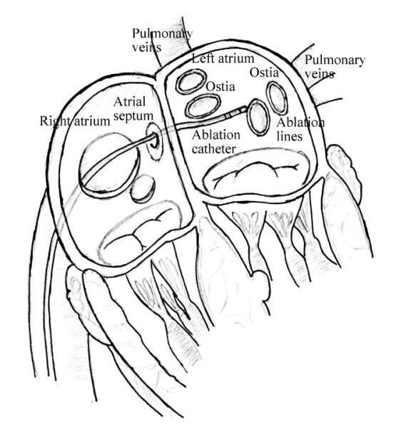
Illustration of catheter ablation procedure.
This paper presents the three dimensional kinematic modeling of a steerable robotic ablation catheter system actuated by a novel actuation method which uses the magnetic field of a magnetic resonance imaging (MRI) scanner. In this actuation method, which was originally proposed by Gudino et al. [2], the catheter is embedded with a set of current-carrying micro-coils. The catheter is actuated by the magnetic forces generated by the magnetic field of the MRI scanner on these coils, by controlling the amount of current going through the coils. The kinematic configuration of the catheter and the deflection under loads of force and torque are modeled using a finite differences approach. The deformation of each segment in the finite differences model is computed using beam theory under mechanical equilibrium conditions. The direct kinematic model is built by using these models.
The focus of the modeling presented here is the active bending of the catheter to perform the ablation once it is inside the left atrium (Fig. 1). In the ablation procedure, the catheter is remotely controlled by the physician after it is manually inserted into the desired position in the left atrium. Due to the penetration through the atrial septum, which has substantial frictions at this location, it is reasonable to assume that the catheter in the left atrium is fixed to the atrial septum. Our current priority is modeling the catheter’s deflection motions in free space and validating this free-space model with the proof-of-concept prototype’s experimental results [2], as this modeling will play a significant role in the following research. As the material of the proof-of-concept catheter is the manufacturer’s proprietary information, estimating these mechanical parameters based on the experimental results are also presented.
The rest of the paper is organized as follows. Related studies in the literature regarding magnetically steerable catheter systems and catheter modeling are discussed in section II. The modeling of the active catheter is presented in section III. Estimation of the mechanical properties of the catheter prototype is presented in section IV. The validation of the proposed model, including comparisons with experimental deflection results reported in [2], are presented in section V. The discussion and conclusion are presented in section VI.
II. Related Studies
There are several types of active catheters proposed in the literature employing different actuation methods. Magnetic actuation is one of the active and growing actuation methods employed. One advantage of magnetic actuation is the ability to place the actuation on the tip rather than at the distal end outside patient body, thus increasing the bandwidth by reducing backlash and friction.
In general, there are two ways of using magnetic actuation for catheter’s navigation. The first method is to place a permanent magnet on the catheter tip and stay in an external magnetic field. The Niobe® ES magnetic navigation system (Stereotaxis, St. Louis, MO) utilizes two permanent magnets mounted on two pivoting arms located on either side of surgical bed to navigate the catheter [3–5]. The catheter, which has a permanent magnet mounted on its distal tip, is placed in the external magnetic field which can selectively change directions and magnitudes. The attraction and repulsion among the magnets are then used to deflect the catheter as desired. Similarly, Lalande et al. [6] showed that a catheter with some ferromagnetic spheres attached on its tip can be bent and steered inside a MRI system by using magnetic gradients. The second approach is to utilize the physical phenomenon that a current-carrying wire in an external magnetic field is able to produce a magnetic force. Gudino et al. [2], Roberts et al. [7], and Settecase et al. [8], separately demonstrate that a catheter with an array of current-carrying coils mounted on its distal tip can perform an arbitrary 3-dimensional deflection inside clinical MRI scanners.
There are a number of earlier studies on modeling of a catheter under a combined loading. Large deflection models of cantilever beams in a 2-dimensional plane are proposed in the field of mechanics of material [9–11]. Khoshnam et al. [12] modeled the distal section of a catheter by using beam theory. However, these traditional beam theories are not directly extendable to the 3-dimensional catheter deflections as well as torsions. The beam theory can not solve the problem with large deflection angles. Some numerical approaches have been proposed. For example, Cotin et al. [13] assumed the catheter is composed of wire-like segments and developed an incremental finite element model based on beam theory. Lawtwon et al. [14] used rotation group and its algebra to derive the Euler differential equations that described the equilibrium configurations of catheters through potential energy relations. Furthermore, Tunay [5] from Stereotaxis developed a simpler quasi-3D Lawtwon’s model.
This paper proposes a new approach combining finite differences approach, beam theory and rotation groups to analyze the catheter’s 3D deflection motion. First, the catheter is approximated to be composed of a set of finite segments. The deflection problem of each small segment is assumed to have small deflection angles, and solved by beam theory and the Bernoulli-Euler law. Once each segment’s deflection angles and torsion angle are known, the positions of all points on this segment can be found. Considering the each segment as a robot link with the two ends of the segment as the link’s joints, the homogeneous transformation relationship between the two ends of the segments are calculated. Using these, the homogeneous transformation relationship between any two ends from two segments can be found. The equilibrium configuration about force and torque of each segment are then set up based on each segment’s deflection angles.
III. Methodology
A. Active Catheter Description
The catheter prototype made by mounting an array of current-carrying coils to the tip of a microcatheter, as shown in Fig. 2. The set of coils includes one (or more) axial coil, and two (or more) orthogonal side coils. The catheter is subjected to a combined loading from an array of external magnetic torques on the coils, and the forces from the weight of catheter and steering coils, and lifting force from the fluid.
Fig. 2.
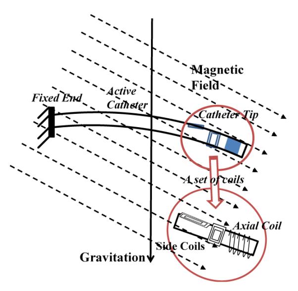
Illustration of a catheter prototype in a magnetic field, including a set of embedded current-carrying coils.
Several assumptions will be used: 1) Catheter is made of a linear material, that is homogeneous and isotropic.1 2) The shear stresses are negligible.2 3) Catheter is nonextensible and the strains remain small. 4) The Bernoulli-Euler hypothesis is valid.3 5) The bending motion and torsion motion are linearly independent.
B. Modeling of Catheter Deflection Mechanism in Free Space
The catheter is a long and tiny tubing. As the deflection angle is sometimes large, this long tubing could not be analyzed as a whole beam by beam theory. Therefore, finite difference approach is applied to analyze the deflection of the catheter by dividing it into N tiny segments (shown in Fig. 3). Each segment has two coordinate frames attached to its two ends. Observed from left to right, the frames are specified as frame 1, frame 2, ⋯, frame N, and frame N + 1. The coordinate frame 1 is catheter’s base frame. Here, the rotation matrix R and the rigid body homogeneous transformation g are used to represent the transformation relationship between any two frames. The vector represents the magnetic field relative to the base frame, [Bx, By, Bz]T. , and represents the magnetization vectors of coil 1, coil 2 and coil 3 relative to frame N + 1, respectively, where , and . Hence, the total magnetization vector relative to frame N + 1 is as follows:
| (1) |
where Nj represents the number of turns in the coil j, Aj is the area enclosed by each turn of the coil j, and ij is the current through the coil j.
Fig. 3.
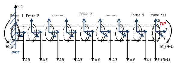
Diagram of a catheter divided into N finite segments.
The catheter is also under the load of the gravitational forces and the lifting forces from the blood fluid. In Fig. 3, the total weight F of coils, assumed as a lumped-force, is located at the tip of catheter. The weight of each segment, assumed to be a lumped-force rather than a distributed force, is located in the middle of the segment. The lifting force from the fluid has an opposite direction against gravitational force. So the combined force at each segment is given by
| (2) |
where V represents the volume of the segment, h is the gravity constant, and ρcath and ρfluid represent the density of the catheter and the fluid, respectively.
1) Equilibrium Configurations of the Individual Segments
Fig. 4 shows the free-body diagram of the Nth segment, the two ends specified by frame N and frame N+1. At the right end, it only has the weight of active coils FN+1 relative to the frame N + 1, and the magnetic torque MN+1. The force FN+1 and the torque MN+1 can be represented relative to the frame N + 1,
| (3) |
| (4) |
where RN+1, 1 represents the rotation matrix between the frame N +1 and the base frame. The equilibrium conditions of the lumped-force ΔW, the torque MN, and force FN are
| (5) |
| (6) |
where PN, N+1 represents the vector between the frame N and the frame N + 1, and QN, N+1 represents the vector between the frame N and the center of this segment.
Fig. 4.
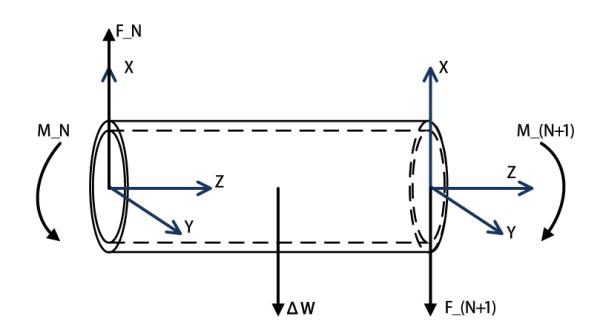
Equilibrium configurations of the last segment.
The free-body diagrams of the (N – 1)th and Nth segments are shown in Fig. 5. The equilibrium conditions of the (N – 1)th segment are,
| (7) |
| (8) |
Fig. 5.

Equilibrium configurations of two neighbor segments.
Similarly, for the rest of the segments, the force and torque equilibrium equations can be written for the Kth segment, K ∈ {N – 2, ⋯, 1}, as
| (9) |
| (10) |
2) Deflection Modeling of the Individual Segments
The deflection of each segment is caused by bending in its X and Y axes, and the torsion around its Z axis.4 The YZ plane in Fig. 6 (a) shows that this segment is bended by the torque Mx around the positive X axis. The two line segments AB and CD represent the intersection of the YZ plane with the two planes perpendicular to the neutral axis of the segment. The extensions of AB and CD intersect at point O2, the center of the circularly deformed segment covering an arc of θx radians. The radius from the center O2 to the neutral axis is represented by R. The curve ‘ab’ is at a distance y from the neutral axis on the positive Y axis. The arc length of the neutral axis is represented by Δs’.
Fig. 6.
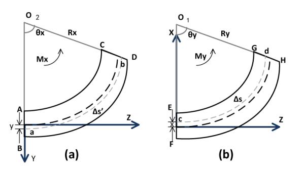
Diagrams of the deformations of one segment by bending in YZ and XZ planes. (a) Bending in YZ plane. (b) Bending in XZ plane.
By the geometry of the sector,
| (11) |
As the segment has a small deflection, we can approximate
| (12) |
where Δz is the length of each segment. So the Eq. 11 is changed to
| (13) |
The geometry of the sector provides the arc length of ab,
| (14) |
The strain of this segment equals
| (15) |
using Eqs. 13 and 14. Then Eqs. 13 and 15 yield
| (16) |
As Hooke’s law provides the stress-strain relation,
| (17) |
we obtain
| (18) |
Applying a similar derivation, the deflection in the XZ plane shown in Fig. 6 (b), can be calculated as
| (19) |
Therefore, the normal stress can be calculated as
| (20) |
following an analysis similar to [15], where Ix and Iy are the area moments of inertia of the segment cross section with respect to the X and Y axes, respectively, and Ixy is the area product of inertia of the segment cross section.
Eqs. 18, 19, and 20 with x = 0 and y = 0, respectively, yield
| (21) |
which gives the bending angles θx and θy as a function of moments applied Mx and My.
The torsion motion of the catheter is shown in Fig. 7. The moment vector Mz is along the Z axis and the torsional angle is denoted by θz. The torsion equation as explained in [15], is
| (22) |
where G is the shear modulus and J is the polar moment of inertia.
Fig. 7.
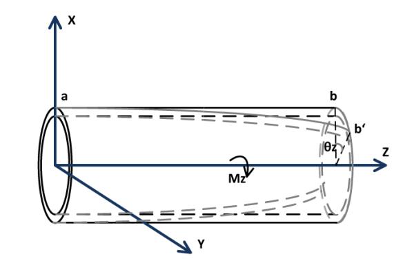
Diagram of the deformation of one segment by a torsion.
Algebraically, Eqs. 21 and 22 can be arranged into a matrix form as
| (23) |
where
and
Simultaneous solutions of Eq. 23 for all of the segments would yield the deflection and torsion angles for all segments. Once the deflection angles are calculated, the coordinate of the end point on each segment can be calculated as
| (24) |
in its own frame.
IV. Estimation of Catheter Prototype’s Mechanical Parameters
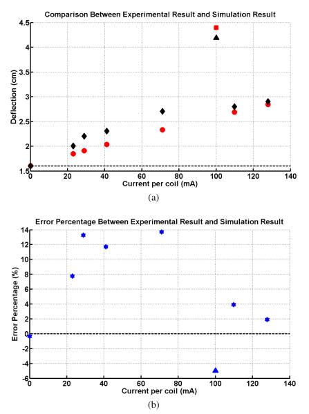
The quantitative comparisons between the simulation results of the proposed model and the experimental results of the catheter prototype presented in [2] under the same experimental environment validates the proposed model of the catheter system. Fig. 8 shows this proof-of-concept prototype built by Gudino [2], which is made by a 2.5 Fr (0.83mm) fiber braided microcatheter (Renegade, Boston Scientific). An array of current-carrying coils made of 42 gauge wire is mounted at the tip of the catheter, coil 1 with a 15-turn square side coil, coil 2 with a 70-turn axial coil and coil 3 with a 70-turn axial coil. It is immersed in a water phantom containing 1% Gd-DTPA, which is placed in MRI scanner. The experimental setup is shown in Fig. 9. The magnetic field with an amplitude of B1 = 1.5 T, is pointing horizontally right and perpendicular to the catheter shape in zero configuration. The direction of gravity points vertically down. The experimental result of the total deflection of the catheter is shown with black markers in Fig. 10(a). They measure 8 quantitative deflections with 8 different currents by exciting coils.
Fig. 8.
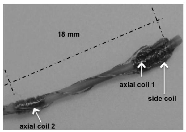
Diagram of the proof-of-concept catheter prototype [2].
Fig. 9.
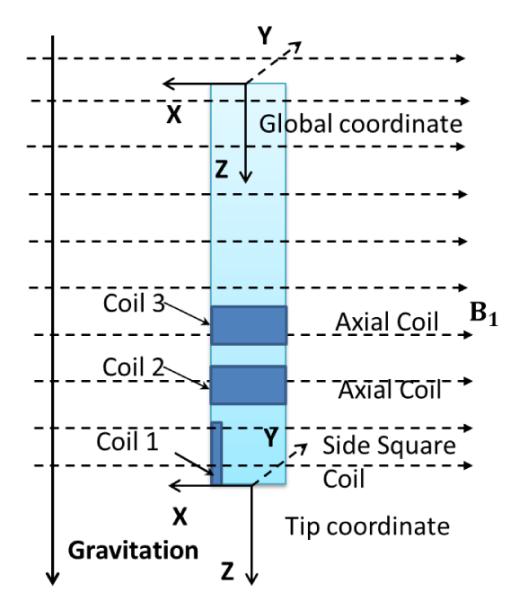
Simplified diagram of the catheter in a magnetic field. Coil 1 is the square side coil. Coil 2 and 3 are the axial coils. B1 = 1.5 T. The direction of the magnetic field points right, while the direction of the gravity points down.
Fig. 10.
The simulation result of the deflection of the catheter by sequentially exciting active coils. (a) The black diamonds represent the experimental deflections by exciting only the distal axial coil and the black triangle represents the largest deflection in the experiment. The red circles represent the simulation deflections by exciting the same axial coil and the red square represents the largest deflection in the simulation. (b) The percentage error between the simulation results and experimental results.
However, the actual material of this microcatheter is unknown, as it is the proprietary information of the catheter manufacturer. We need to estimate the mechanical parameters of this catheter material, i.e., its density, young’s modulus, poisson’s ratio and shear’s modulus, prior to the validation of the proposed models. Additionally, the experimental data indicates that there is an initial catheter tip deflection, 1.5991 cm as shown in Fig. 10(a), when no current input to the catheter, due to the natural bent of the catheter. In this study, this rest bending of the catheter is approximately modeled by an external force acting on the catheter tip, which also needs to be estimated.
These parameters are estimated from 3 data points, corresponding to the rest deflection of the catheter (no current applied), largest deflection obtained by exciting all three coils at 100 mA, and the deflection obtained by exciting only the distant axial coil at 130 mA. The parameters are then estimated by finding the set of parameters that minimizes the error between the actual deflection measurements and the deflections estimated by the model.
The computation of this minimization problem provides us a set of appropriate parameters as: young’s modulus 350MP a, poisson’s ratio 0.3, density 900kg/m3, and the external force 2.00 × 1.0e−4N.
V. Simulation Results
Equipped with the appropriately estimated mechanical parameters obtained in Section IV, the proposed model is used to estimate the total deflection of the catheter by sequentially exciting the active coils, as shown in Fig. 10. The experimental results obtained by exciting only the distal axial coil at the tip from 0 mA to 130 mA, are marked with black diamonds in Fig 10(a). Under the same excitation, the simulation deflections computed by the proposed model are marked with the red circles. The black triangle represents the largest experimental deflection by exciting all active coils, while the red square represents the corresponding largest deflection in the simulation. Fig. 10(b) shows the percentage error between the corresponding experimental and simulation deflections. It is confirmed that the percentage errors of the three characteristic deflections are small, as minimizing them gets the estimation parameters. The largest percentage error is less than 14%. These comparisons demonstrate that the model matches with the experimental results.
VI. Discussion and Conclusion
In this paper, a 3D model of a steerable catheter using an array of active steering coils in a magnetic field in free space is presented. In the proposed method, the catheter is modeled as a series of finite segments. The deflection displacement and torsion angle for each segment at the quasi-static equilibrium condition were calculated using beam theory. The catheter’s deflections estimated by the proposed model matches with the experimental results collected by Gudino et al. [2] under the same experimental conditions.
The computation time of the proposed model for computing the tip location is important concerns for clinical applicability of the methods. The numerical computation of the direct kinematic model given the current inputs takes approximately 4 seconds on a computer equipped with Intel® core i7-960 CPU @ 3.20 GHz and 12.0 GB memory, running 64-bit Microsoft Windows 7 operating system. The calculation is implemented in Matlab→ 7.11.0 (R2010b).
In the future, this proposed catheter model will be used to optimize the catheter prototype design according to the clinical ablation application. The design issues include the selection of the material and the dimension of the catheter, the type and the number of coils, the number of winding per each coil, the placement of the coils and so on.
Acknowledgments
*This work was supported in part by NSF under grants IIS-0905344 and CNS-1035602, and National Institutes of Health under grants R21 HL096941 and R01 EB018108.
Footnotes
Hooke’s law is applicable.
The length L of the catheter is much larger than the maximum cross-section diameter D, which indicates the maximum shear stress is small compared to the maximum normal stress. More details are specified in [15].
I.e., plane cross-sections, which are normal to the neutral surface, remain normal during the deformation.
These motions obey the assumptions given in Section III-A.
References
- [1].What Is Catheter Ablation? National Heart Lung and Blood Institute; http://www.nhlbi.nih.gov/health/health-topics/topics/ablation/ [Google Scholar]
- [2].Gudino N, Heilman JA, Derakhshan JJ, Sunshine JL, Duerk JL, Griswold MA. Control of intravascular catheters using an array of active steering coils. Medical physics. 2011 Jul;38(no. 7):4215–4224. doi: 10.1118/1.3600693. [DOI] [PMC free article] [PubMed] [Google Scholar]
- [3].Niobe® ES Magnetic Navigation System. Stereotaxis; http://www.stereotaxis.com/niobe.html. [Google Scholar]
- [4].Tunay I. Position control of catheters using magnetic fields. Mechatronics, 2004. ICM ’04. Proceedings of the IEEE International Conference; June 2004.pp. 392–397. [Google Scholar]
- [5]. — Modeling magnetic catheters in external fields. Proceedings of the 26th Annual International Conference of the IEEE EMBS; San Francisco, CA, USA. September 1-5, 2004; pp. 2006–2009. [DOI] [PubMed] [Google Scholar]
- [6].Lalande V, Gosselin FP, Martel S. Catheter Steering Using a Magnetic Resonance Imaging System. 32nd Annual International Conference of the IEEE EMBS; August 31 - September 4 2010; [DOI] [PubMed] [Google Scholar]
- [7].Roberts TPL, Hassenzahl WV, Hetts SW, Arenson RL. Remote control of catheter tip deflection: An opportunity for interventional mri. Magnetic Resonance in Medicine. 2002 Dec;48(no. 6):1091–1095. doi: 10.1002/mrm.10325. [DOI] [PubMed] [Google Scholar]
- [8].Settecase F, Sussman MS, Wilson MW, Hetts S, Arenson RL, Malba V, Bernhardt AF, Kucharczyk W, Roberts TPL. Magnetically-assisted remote control (marc) steering of endovascular catheters for interventional mri: A model for deflection and design implications. Medical physics. 2007 Aug;34(no. 8):3135–3142. doi: 10.1118/1.2750963. [DOI] [PMC free article] [PubMed] [Google Scholar]
- [9].Chen L. An integral approach for large deflection cantilever beams. International Journal of Non-Linear Mechanics. 2010;45(no. 3):301–305. [Google Scholar]
- [10].Lee K. Large deflections of cantilever beams of non-linear elastic material under a combined loading. International Journal of Non-Linear Mechanics. 2002;37(no. 3):439–443. [Google Scholar]
- [11].Belendez T, Neipp C, Belendez A. Large and small deflections of a cantilever beam. European Journal of Physics. 2002;23(no. 3):371. [Google Scholar]
- [12].Khoshnam M, Azizian M, Patel RV. Modeling of a steerable catheter based on beam theory. IEEE International Conference on Robotics and Automation; RiverCenter, Saint Paul, Minnesota, USA. May 14-18 2012. [Google Scholar]
- [13].Cotin S, Duriez C, Lenoir J, Neumann P, Dawson S. New approaches to catheter navigation for interventional radiology simulation. Proceedings of medical image computing and computer assisted intervention (MICCAI); Palm. 2005; pp. 300–308. [DOI] [PubMed] [Google Scholar]
- [14].Lawton W, Raghavan R, Ranjan SR, Viswanathan R. Ribbons and groups: a thin rod theory for catheters and filaments. Journal of Physics A: Mathematical and General. 1999;32(no. 9):1709. [Google Scholar]
- [15].Boresi AP, Schmidt RJ. Advanced Mechanics of Materials. 4th ed John Wiley and Sons, Inc; 1985. [Google Scholar]


