Abstract
Functional Magnetic Resonance Imaging (fMRI) has established itself as the main research tool in neuroscience and brain cognitive research. The common marmoset (Callithrix jacchus) is a non-human primate model of increasing interest in biomedical research. However, commercial MRI coils for marmosets are not generally available. The present work describes the design and construction of a 4-channel receive-only surface RF coil array with excellent signal-to-noise ratio (SNR) specifically optimized for fMRI experiments in awake marmosets in response to somatosensory stimulation. The array was designed as part of a helmet-based head restraint system used to prevent motion during the scans. High SNR was obtained by building the coil array using a thin and flexible substrate glued to the inner surface of the restraint helmet, so as to minimize the distance between the array elements and the somatosensory cortex. Decoupling between coil elements was achieved by partial geometrical overlapping and by connecting them to home-built low input impedance preamplifiers. In vivo images show excellent coverage of the brain cortical surface with high sensitivity near the somatosensory cortex. Embedding the coil elements within the restraint helmet allowed fMRI data in response to somatosensory stimulation to be collected with high sensitivity and reproducibility in conscious, awake marmosets.
Keywords: animal models, marmosets, magnetic resonance imaging, phased arrays, receive-only RF coils
Introduction
Functional Magnetic Resonance Imaging (fMRI) has become an essential and powerful tool in neuroscience and brain cognitive research, both in translational and clinical studies (1,2). The use of animal models plays a fundamental role in basic science research. Due to their close similarity with humans, nonhuman primate (NHP) species constitute excellent models to study the causes and potential treatments for many human disorders (3). Among the NHP species used in neuroscience research, the common marmoset (Callithrix jacchus) has distinct advantages when compared to Old World primates (4), such as prolific reproduction in captivity, early sexual maturity reached by 18 months of age and enhanced biosafety. One challenge of using marmosets for MRI and fMRI experiments is that, at this time, there are no RF coils commercially available which satisfy the anatomical constraints imposed by these animals. Currently, the most common commercially available RF coils manufactured for animal models are offered for rodents (rats and mice), or for rhesus monkeys. However, the development of specific RF coil designs for marmosets is not widely available.
As any animal model, marmosets are naturally non-compliant subjects in the MRI scanner. While the use of anesthesia is a safe and effective way to ensure compliance, minimize movements and alleviate stress during experiments, anesthesia brings in the disadvantages of interfering with both neural activity and neurovascular coupling, thus compromising the interpretability of results (5-7). In addition, anesthesia prevents study of the conscious brain, hindering a number of applications of fMRI to study behavioral and cognitive processes. A frequently employed solution to avoid the physiological drawbacks of anesthesia is to physically restrain the animals by specially designed chairs, and to immobilize their heads by surgically implanted head posts (8-17). These posts are very effective in providing maximum motion restraint, but have a few disadvantages. First, they are invasive and thus detract from the main advantage of MRI as a non-invasive technique. Second, they require constant aseptic cleaning to prevent infections. Third, the use of implant materials restrict free placement of RF coils on the surface of the head. In addition, because implant materials are typically lossy, they deteriorate the Q factor of the coils and may introduce susceptibility artifacts at high field strengths. Nevertheless, minimization of the distance between the coil and the monkey’s brain is crucial to maximize the signal-to-noise ratio (SNR) of the MR images. For example, an SNR gain in excess of 5 fold was achieved by implanting an 8-channel receive-only coil array on the skull of rhesus macaques when compared to coils placed externally around the animal’s head (18).
To overcome the above-mentioned problems of using implanted head posts as head restraints, a completely non-invasive individualized helmet system was devised to allow comfortable restraint of awake marmosets in the MRI scanner (19,20). When combined with acclimatization procedures to condition the animals to tolerate physical restraint and exposure to MRI sounds, these restraining helmets have proven to be an effective method to accomplish fMRI experiments with conscious, awake marmosets. The purpose of the present work was to develop a 4-channel receive-only array embedded in the restraining helmets to maximize the SNR for fMRI experiments of the marmoset’s somatosensory cortex at 7 T. Each element of the array was made using a flexible substrate with single sided copper and was embedded in the inner surface of the helmets, minimizing the distance between the array and the cortical brain surface while still providing comfort to the animal. Decoupling between coil elements was achieved by partial geometrical overlap of the nearest neighbors and by connecting each element to home-built low input impedance preamplifiers (21,22).
Theory
Geometrical Considerations
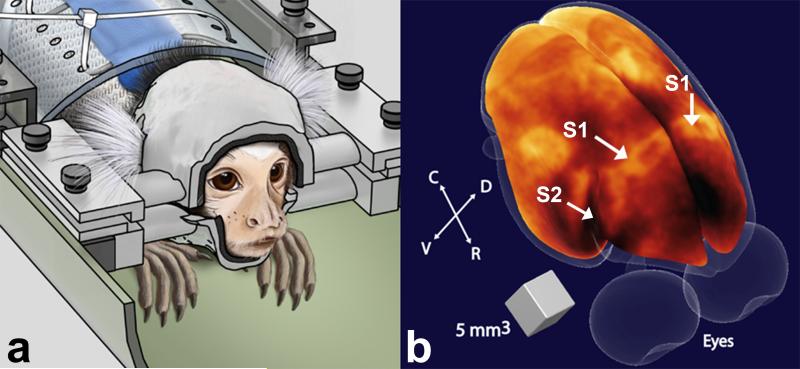
Like humans, each marmoset has a different skull size and shape, requiring the development of individual custom-built non-invasive restraint helmets during MRI/fMRI experiments (19). In order to take full advantage of these individualized helmets to maximize the SNR in the region of interest, the head size and shape, and the location of the marmoset primary (S1) and secondary somatosensory cortex (S2) (23), as depicted in Figure 1, were used as geometrical constraints for the design of a 4-element phased array coil (24,25). In the marmoset, S1 spans about 5 mm in the rostrocaudal direction, and about 8 mm in the mediolateral direction (23). S2 sits immediately lateral to S1 in the inner bank of the lateral sulcus, and spans about 4 mm both in the rostrocaudal as well as in the mediolateral direction (23) (Figure 1). Therefore, we determined that the array would need to have high sensitivity to a depth of about 15 mm below the skull, and each element was chosen as a loop with 15 mm inner diameter. To maximize the sensitivity without compromising the animal’s comfort, flat, flexible and thin conductors were used instead of round wires and laid out on the inner surface of the helmets.
Figure 1.
(a) Illustration of a marmoset in the sphinx position restrained by the custom-fit helmet (left). (b) Volumetric rendering of the brain surface of a marmoset obtained from a 3D T1-weighted image (43). Regions of high myelination appear bright in the image. Arrows indicate the locations of primary (S1) and secondary (S2) somatosensory cortex. R = rostral; C = caudal; D = dorsal; V = ventral.
Signal-to-Noise Considerations
Next, the sources of loss to be minimized during coil development were determined. For the majority of applications involving small animal models, resistive losses introduced by the sample, the coil’s discrete elements and the transmission line have to be taken into account (26,27). Doty et al. defined small animal coils as mid-range coils, where the product of the frequency f and the coil diameter d are within the range 2 – 30 MHz·m (26,28). For these coils, assuming that all resistive losses are at the same temperature Tn, Equation [1] can be used to estimate the SNR following a single 90° pulse:
| [1] |
where VS is the sample volume, PT is the total transmitter power required to generate B1, when applied at the coil port with the preamp disconnected. While the above expression has been derived for transmitter coils, it can also be used for receive-only coils and coil arrays via the principle of reciprocity (29-31). Optimization of mid-range coils consists of maximizing the coil efficiency by enlarging B1 via placement of the coil conductors as close as possible to the sample, and by minimizing PT with the use of low-loss components, such as capacitors, inductors, diodes, etc. However, for typical RF coil dimensions commonly used in small animal applications, there is a compromise between maximizing the efficiency of the array elements and simultaneously achieving good preamp decoupling by attaching them to low input impedance preamplifiers.
Due to space limitations in coils designed for small animal applications and in order to avoid image artifacts caused by the proximity of the preamplifiers, it is common to insert a length of RF cable in between the coil and the low input impedance preamplifiers, as illustrated by the electric scheme shown in Figure 2 (24,32-35). To make use of the low input impedance of the preamplifiers to minimize the effects of inductive coupling between array elements it is necessary to choose the electrical length of the cable be equivalent to a λ/2 cable, providing 180° phase at the input of the preamplifier. In this case, the circuit comprised by the inductor LD, the capacitor CM and the preamplifier shown in Figure 2 will form a parallel resonant circuit that blocks the current flowing in the coil, while still receiving and transferring the NMR signal to the preamplifier. The magnitude of the impedance produced by this resonant block circuit as viewed by the coil perspective (Za in Figure 2) can be expressed as (32):
| [2] |
where Rp is the input impedance of the preamplifier considering the additional λ/2 RF cable. Equation [2] shows that the effectiveness of the preamplifier decoupling is proportional to the inductance LD and inversely proportional to the preamplifier input impedance. So, if on the one hand CM and LD should satisfy the 50 Ω matching condition (24,32), on the other hand it is necessary to keep LD high enough to provide a good isolation through preamp decoupling. For coils with very small dimensions that have small values for the loaded coil resistance, the value of the inductor LD may be too low and thus difficult to realize in practice. A good rule of thumb is to find values for CM and LD that provide a return loss of typically 20 dB. At the same time, it is recommended to achieve at least 15 dB of isolation due to preamp decoupling (33-35).
Figure 2.
Circuit diagram of one coil element used in the 4-channel embedded array. The electrical length of the RF cable + phase shifter was adjusted to provide 180° phase at the input of the preamplifier. The detuning circuit consisting of CM and LD is activated by providing DC current to the PIN diode via a bias T located before the low input impedance preamplifier.
Materials and Methods
Helmet manufacturing process
The manufacturing procedure of the individualized helmets started with the acquisition of a 3D gradient echo image of the anesthetized marmoset’s head and torso (Figure 3a) using the transmit body coil in transceiver mode. An actively detunable 16-rung linear birdcage coil with inner diameter of 108mm was used as the transmit coil. The 3D images were acquired with FOV=7.68 × 7.68 × 7.68 cm3, matrix size=160 × 160 × 160, TE=1.7 ms, TR=15 ms, 4 averages, resulting in a total acquisition time of 25.6 min. The next step was to do a semi-automatic segmentation process using the software ITK-SNAP (University of Pennsylvania, Philadelphia, PA) to obtain a 3D head mesh profile. The mesh was then imported into a 3D modeling program, Rhinoceros 3d (McNeel North America, Seattle, WA) to obtain the 3D contour surface of the head (Figure 3b). A matching 3D surface was created and enlarged by 2 mm in all directions to create space for the compressible foam that lines up the inner surface of the helmet to provide a comfortable restraint of the head. This 3D surface was then used to create a solid helmet and separated into top (head) and bottom (chin) pieces, to which lateral bars were added for support. The pieces were printed in a 3D printer (1200es Series 3D Printer, Stratasys, Inc., Eden Prairie, MN), out of ABS plastic material, as depicted in Figure 3c. Finally, the array elements were fixed to the inner surface of the top (head) piece, as shown in Figure 3d and detailed in the following paragraphs.
Figure 3.
Schematics of the manufacturing process of the movement restraint helmets. (a) 3D gradient echo images from head and torso are acquired with the body coil in transceiver mode. (b) Surface rendered model obtained from the gradient echo images. (c) From the surface rendered model, the helmets are designed using Rhinoceros 3d and printed in ABS plastic by a 3D printer. (d) 4 overlapped array elements are attached to the inner surface of the helmets, with the matching networks placed on the external side.
4-channel coil array construction
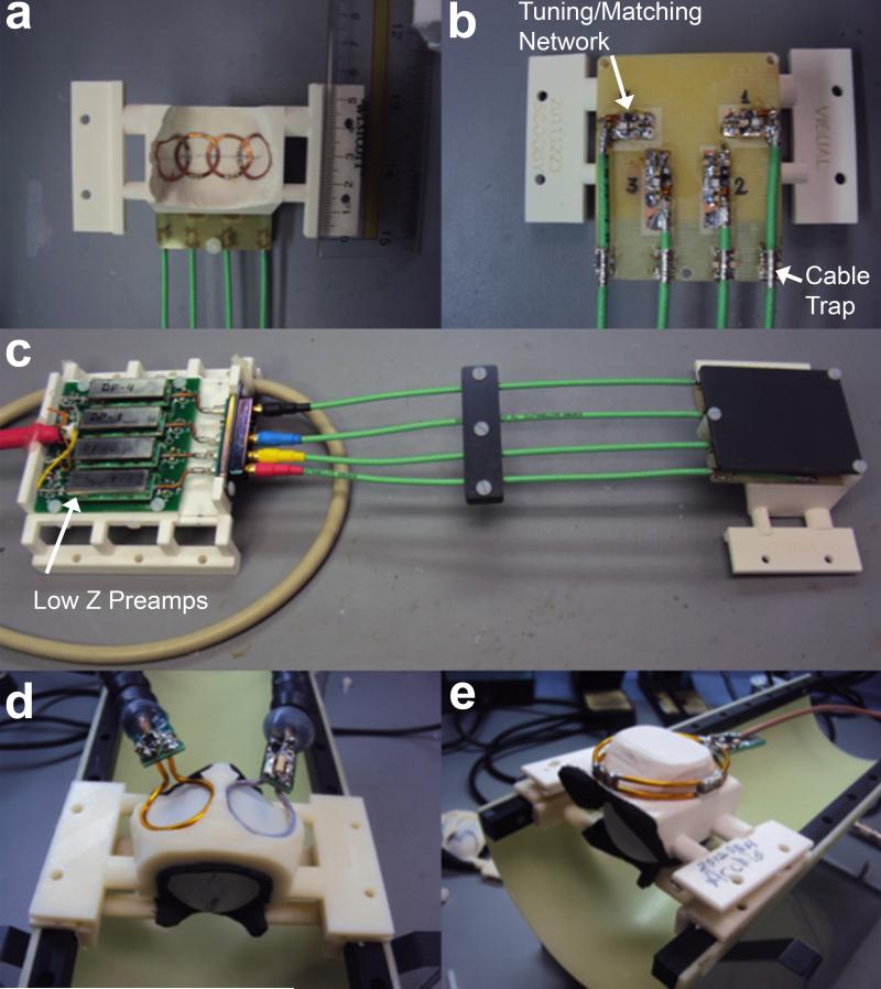
In order to attach the array elements on the inner surface of the helmets without compromising comfort to the animals, each element of the array was made using CuFlon (Polyflon Inc., Norwalk, CT, USA) with 2 oz/ft2 of copper deposited in a 0.25 mm thick PTFE dielectric. This flexible and thin material allowed the coils to be glued tight onto the inner surface of the helmet and to adopt its 3D contour, as shown in Figure 4a. The inner diameter of each 1.5 mm wide circular loop was 15 mm, and the connection between the coil elements and the matching networks, placed on the outer surface of the headpiece, were made by soldering copper wire 0.025” diameter (AWG 22) with length of approximately 3-4 mm through the helmet’s plastic wall. This separation from the array elements to the matching network board was verified to be sufficient to avoid any interference effects between the board and the coil elements. The layout of all four matching networks was milled in the same FR4 substrate (Figure 4b) using a 2-D milling machine (Modela MDX-20, Roland DGA Corp., Irvine, CA). Decoupling between coil elements was minimized by partial overlapping of each pair of nearest neighbor coils by direct S21 measurements that were carried out with the other two coils not under test detuned. These measurements had to be performed with the coils unloaded due to the need to position the elements on the inner surface of the restraint helmet. After the optimal position for each element was found, the coils were glued in place and the inner surface of the helmet was covered by polyurethane foam (3 mm thickness) to provide additional comfort to the animals during the MRI and fMRI experiments. Additionally, all four elements were connected to homebuilt low input impedance preamplifiers through a π-network phase shifter combined with 22 cm of RF cables (RG 316/U-12, Huber+Suhner AG, Herisau, Switzerland). The electrical length of the RF cable + phase shifter was adjusted to provide an equivalent λ/2 cable at the input of the preamplifier as shown in the electric scheme of Figure 2. The components used for the tuning/matching network consist of non-magnetic chip capacitors (A series, American Technical Ceramics, Huntington Station, NY), air core inductors for the detuning and phase shifter (micro spring air core inductors, Coilcraft Inc., Cary, IL) and PIN diodes (Temex Ceramics, Pessac, France) for the active detuning. To simulate the equivalent loading conditions of the marmoset head on the array, a spherical phantom of 35 mm in diameter was filled with a solution of 9 g/L sodium chloride, and each array element was tuned and matched using this phantom. To detune the coil during the transmit period, a blocking circuit consisting of CM and LD is activated by providing DC current to the PIN diode via a bias T located before the low input impedance preamplifiers. To avoid cross-talking interactions between the RF coaxial cables, cable traps tuned to 300.4 MHz were inserted after the matching network and before the input of the preamplifiers. The homebuilt preamplifiers (21,22) were designed typically with input impedance of 1.5 Ω, gain of 33 dB, output impedance of 50 Ω and noise figure of 0.8 dB. All coaxial cables attached to the coils were connected to the input impedance preamplifiers using hook up connectors (types FMX012S128, FCT GmbH, Munich, Germany), as shown in Figure 4c.
Figure 4.
(a) Inner surface of helmet showing each element of the embedded 4-channel array. (b) External part of the coil containing the printed circuit board with the matching networks. (c) 4-channel embedded array connected to the low input impedance preamplifiers. For performance evaluation, the embedded 4-channel array was compared to two circular surface coils externally positioned in circular grooves at the helmet top (d), and to a single elliptical surface coil covering the whole marmoset head (e).
Characterization on the bench and SNR maps
Each channel was characterized on the workbench by evaluating the isolation due to preamp decoupling and active detuning when compared to the power-matching situation. The transmission coefficient S21 was measured using a pair of decoupled pick up loops and comparing the S21 response in the network analyzer when the coil was power matched, noise matched and actively detuned by the PIN diodes. The unloaded/loaded quality factor ratio QU/QL and the frequency shift caused by loading the coil with the spherical phantom were measured for each channel of the array, with the other coil elements not under test actively detuned by the PIN diodes. To evaluate the performance of the active detuning circuit, the transmit B1+ field map was measured experimentally using the Double Angle Method (36) comparing two different situations: placing the spherical phantom without (a) or with (b) the actively detuned receive array in the volume transmit RF coil. SNR maps (37) were acquired using the spherical phantom and compared to those obtained from two different coil setups previously employed for fMRI experiments in awake marmosets in our lab. The first setup consisted of two 17 mm single loop surface coils externally placed on the top part of the helmets, as shown in Figure 4d. The second setup consisted of a single elliptical surface coil with 48 mm major axis and 38 mm minor axes covering the whole marmoset brain, and also placed outside the helmet, as shown in Figure 4e. A noise correlation matrix was also measured for the 4-channel array using the spherical phantom.
Phantom images were acquired using a Rapid Acquisition with Relaxation Enhancement (RARE) sequence with 8 echoes set for the following parameters: TR=1000 ms, TEeff=56 ms, FOV=5.12 × 5.12 cm2, slice thickness = 2 mm, matrix = 256 × 256 and 1 average. In vivo SNR maps were acquired from a conscious awake marmoset using a FLASH sequence with TR=100 ms, TE=7 ms, FOV=3.84 × 3.84 cm2, slice thickness = 2 mm, matrix =256 × 256 and 8 averages, resulting in total scan time of 25 min 36 s. All imaging experiments were performed in a 7T/30 cm USR magnet (Bruker-Biospin, Inc. Ettingen, Germany) connected to an AVIII console running ParaVision 5.1.
Conscious awake MRI/fMRI experiments
FMRI experiments were performed in an adult male marmoset acclimated to the restraint helmet and MRI sounds (19). During the experiments, the animal was continuously monitored by an MR-compatible camera (model 12M, MRC Systems GmbH, Heidelberg, Germany). Blood oxygenation level dependent (BOLD) fMRI was obtained using a 2D gradient-recalled echo planar imaging (EPI) sequence from 8 coronal slices with TR=1000 ms, TE=25 ms, thickness=1 mm, FOV=3.2 × 2 cm2, matrix 128 × 80 and zero-filled to 256 × 160. Bilateral electrical stimulation of the forearm nerves was delivered by pairs of electrode pads placed across each wrist. An off-on-off block design paradigm was applied to the animal with the following stimulus parameters: current intensity 2 mA, pulse duration 0.4 ms, stimulation frequency 50 Hz. Each epoch consisted of a stimulus period of 20 s interleaved between pre- and post-stimulus resting periods of 20 s each. Eight epochs were run for a total fMRI experiment duration of 8 min. Coplanar anatomical T2-weighted images were obtained using a RARE sequence with TR=6000 ms, TEeff=72 ms, matrix = 256 × 160 and 12 averages. Imaging processing and statistical analysis was performed using the software for analysis of functional neuroimages AFNI (38). Slice timing and the rigid-body movement were corrected in the first stage of the process. Epochs with maximum displacement larger than half of the pixel were excluded from averaging. Activation maps were generated by least squares estimation of the linear regression coefficients with a gamma variant hemodynamic response function. Finally, the map was overlaid on the anatomical T2 images after affine transformation.
Results
Characterization on the bench
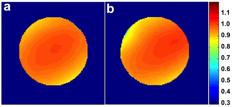
S21 measurements of the decoupling between nearest neighbors performed on the bench resulted in typical values of ~ 17 dB. The isolation due to preamplifier decoupling was measured to be 18 dB on average. For active detuning measurements performed, the isolation obtained from the S21 response was > 38 dB for all channels. Figure 5 shows the transmit B1+ field map normalized by the field at the center of the coil obtained from a spherical phantom without the coil array in the transmit field (Figure 5a) and with the coil array present but actively detuned (Figure 5b. The B1+ field deviated less than 5% at the border of the phantom when the coil array is present, confirming the effectiveness of the active detuning circuit. The average of the QU/QL ratios measured, considering the 3 mm foam between the coil and the phantom, was 120/103 = 1.17. The average frequency shift due to loading effects was −0.25 MHz.
Figure 5.
Normalized transmit B1+ field maps obtained from a spherical phantom using the linearly driven volume birdcage coil in transceiver mode under two different conditions: (a) In absence of the 4-channel coil array. (b) With the coil array present but with all receive elements actively detuned. The two maps differ from each other by no more than 5%.
SNR maps and Noise correlation matrix
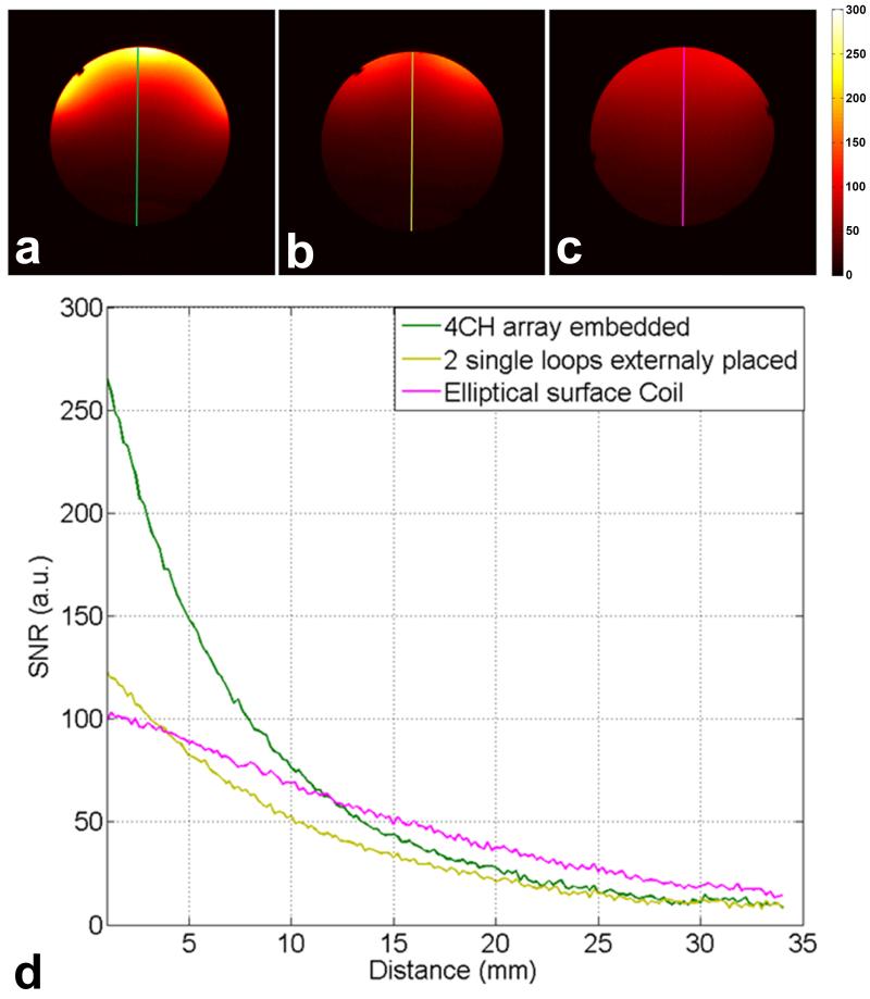
Figure 6 shows phantom SNR maps calculated from sum-of-squares images obtained using the 4-channel embedded array (Figure 6a), the two single loop surface coils placed externally to helmet (Figure 6b) and the single elliptical surface coil (Figure 6c). The SNR profiles comparing the coil performance along the center axis are shown in Figure 6d. At the surface of the phantom, the SNR from the embedded array is 2.1 times higher than that from the two external surface coils and 2.7 times higher than the SNR from the large elliptical surface coil. At 4 mm depth, the two single loop surface coils and the large elliptical surface have similar SNR, while the embedded array is still 1.8 times superior in SNR. After 12 mm the single elliptical surface coil shows higher SNR than the embedded array and the two surface coils.
Figure 6.
Phantom SNR maps calculated from the sum-of-squares images obtained with: (a) the 4-channel embedded array; (b) two single loops externally placed in the helmets; and (c) Elliptical surface coil. (d) Plot of the SNR profiles along the central axis comparing the coils performance.
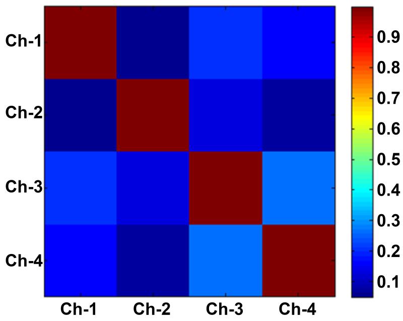
Coupling between all channels was evaluated by acquiring the noise correlation matrix shown in Figure 7. The highest off-diagonal correlation coefficient, which occurred between channel 3 and channel 4, was 0.27, suggesting a small residual coupling between these two channels.
Figure 7.
Noise correlation matrix acquired with the 4-element coil array. The highest off-diagonal correlation coefficient is 0.27, which indicates a small residual coupling between channel 3 and channel 4.
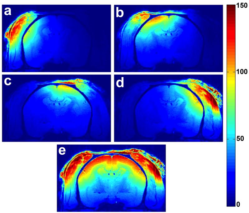
In vivo SNR maps obtained from conscious awake marmosets using the 4-channel embedded array are displayed in Figure 8. The individual element images (Figure 8a-d) show high sensitivity of each coil element to the corresponding portion of the parietal cortex right below. The sum-of-squares resulting image (Figure 8e) shows high sensitivity covering the entire primary somatosensory cortex.
Figure 8.
(a-d) In vivo SNR maps obtained for each individual coil element from an awake marmoset. (e) Sum-of-squares image reconstruction showing excellent coil sensitivity in the cortex.
FMRI experiments
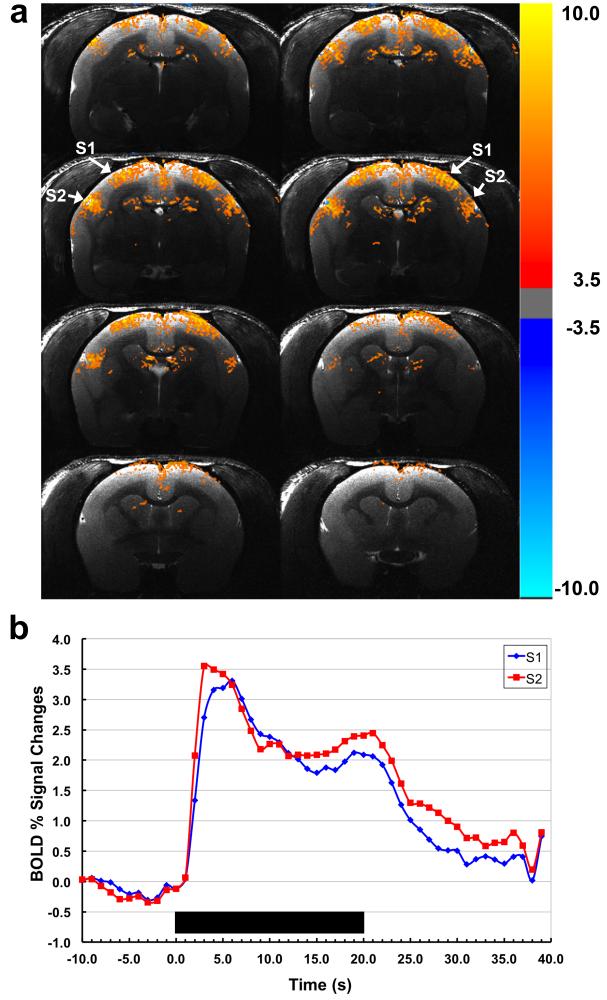
High-resolution BOLD fMRI activation maps obtained from conscious awake marmosets in response to somatosensory stimulation are displayed in Figure 9a, showing robust, bilateral BOLD activation in primary (S1) and secondary (S2) somatosensory cortices. Note that robust activation is detected in S2, which is located further from the reach of the coil array than S1. Figure 9b shows the corresponding BOLD fMRI time courses averaged across the several runs.
Figure 9.
(a) BOLD activation maps obtained from a conscious awake marmoset in response to somatosensory stimulation using the embedded 4-channel array coil. The arrows show the two main regions of activation in the somatosensory cortex, S1 and S2. (b) Normalized averaged time courses showing BOLD signal changes in S1 and S2 (blue and red, respectively). Duration of the stimulation period is indicated by the black bar.
Discussion
We have demonstrated here the development of a 4-channel receive-only RF coil array for fMRI experiments of the somatosensory pathway in conscious, awake marmosets. The array was embedded in individualized movement-restraining helmets, that were previously shown to provide an effective and non-invasive way to restrain head motion during the MRI scans (19). The main advantage of the present design is the placement of the coil elements on the inner surface of the helmets, which increases the sensitivity of detection over the parietal cortex by up to 2.1 times when compared to surface coils placed externally over the helmet.
A major point of difficulty in building the 4-channel array is to achieve satisfactory coil-to-coil isolation across the different channels. The small geometry of each coil loop and their layout in the somewhat irregular inner surface of individualized helmets make it difficult to obtain perfect isolation across the different channels. The additional constraint imposed by the fact that the elements are embedded in the helmet and the matching network are located externally make the initial placement of the elements critical, as once they are glued to the helmet they can no longer be relocated to further improve the isolation. The good coil-to-coil isolation obtained here was due to the combination of partial overlapping of neighboring elements and preamplifier decoupling. Because the coils are laid on a somewhat irregular curved surface, it is difficult to achieve sufficient coil-to-coil isolation based solely on their geometrical arrangement. Due to the low availability of commercial low input preamplifiers, as well as to the tight space in the bore of small animal MRI machines, we have developed our own low-noise, low input-impedance preamp for operation at 7 T and 11.7 T (21,22) with very competitive specifications. The use of low input impedance preamplifiers significantly improved the isolation achieved by geometrical decoupling (33). Measurements of the noise correlation matrix obtained using a loaded phantom confirmed that the coil-to-coil isolation was satisfactory across all four elements of the array.
A main motivation for the present work was the development of dedicated receive-only RF coil arrays for marmosets. To the best of our knowledge, there are currently no commercially available receive RF coil arrays for marmosets. Previous MRI and fMRI studies in marmosets have been conducted using generic RF coils (14,39-42). The use of a design built specifically to take into account the unique shape and size of individual subjects optimizes the sensitivity of the array and provides maximum comfort to the animals. As mentioned above, the main advantage of the embedded array design is placement of the coil elements on the inner surface of the helmets, as close as possible to the cortical area of interest in the brain. The close proximity of the coil elements to the brain boosted the SNR in the parietal cortex by a factor of two. However, the presence of coil wires so close to the surface of the brain can cause susceptibility artifacts and their tight arrangement can reduce the coil-to-coil isolation. We were able to mitigate susceptibility artifacts with the use of a flat and flexible Teflon-based substrate, which prevented us from having to carve grooves on the inner surface of the helmet to accommodate regular wires. The use of a flat substrate provided more comfort to the animals, as it did not change the conforming inner surface of the helmets. However, the use of individualized helmets requires building individualized arrays. We consider this additional workload to be a minor disadvantage compared to the huge payoff obtained from acquiring fMRI data from conscious, awake animals with improved comfort and effective motion restraint.
Acknowledgements
The authors are grateful to Xianfeng (Lisa) Zhang for her excellent technical skills, and to Dr. Stephen Dodd for his help with assembly of the preamplifiers. This research was supported by the Intramural Research Program of the NIH, NINDS and partially supported by the National Council for Scientific and Technological development (CNPq) through the Science without Borders program (process # 207982/2012-0).
Glossary
- ABS
Acrylonitrile butadiene styrene
- AFNI
analysis of functional neuroimages
- BOLD
blood oxygenation level-dependent
- fMRI
functional magnetic resonance imaging
- FOV
field-of-view
- NHP
non-human primate
- RARE
Rapid Acquisition with Relaxation Enhancement
- RF
radio frequency
- S1
primary somatosensory cortex
- S2
secondary somatosensory cortex
- SNR
signal-to-noise ratio
References
- 1.Poldrack RA. The role of fMRI in cognitive neuroscience: where do we stand? Curr Opin Neurobiol. 2008;18(2):223–227. doi: 10.1016/j.conb.2008.07.006. [DOI] [PubMed] [Google Scholar]
- 2.Dolan RJ. Neuroimaging of cognition: past, present, and future. Neuron. 2008;60(3):496–502. doi: 10.1016/j.neuron.2008.10.038. [DOI] [PMC free article] [PubMed] [Google Scholar]
- 3.Capitanio JP, Emborg ME. Contributions of non-human primates to neuroscience research. Lancet. 2008;371(9618):1126–1135. doi: 10.1016/S0140-6736(08)60489-4. [DOI] [PubMed] [Google Scholar]
- 4.Mansfield K. Marmoset models commonly used in biomedical research. Comparative Med. 2003;53(4):383–392. [PubMed] [Google Scholar]
- 5.Masamoto K, Kim T, Fukuda M, Wang P, Kim SG. Relationship between neural, vascular, and BOLD signals in isoflurane-anesthetized rat somatosensory cortex. Cereb Cortex. 2007;17(4):942–950. doi: 10.1093/cercor/bhl005. [DOI] [PubMed] [Google Scholar]
- 6.Masamoto K, Fukuda M, Vazquez A, Kim SG. Dose-dependent effect of isoflurane on neurovascular coupling in rat cerebral cortex. Eur J Neurosci. 2009;30(2):242–250. doi: 10.1111/j.1460-9568.2009.06812.x. [DOI] [PMC free article] [PubMed] [Google Scholar]
- 7.Wegener S, Wong EC. Longitudinal MRI studies in the isoflurane-anesthetized rat: long-term effects of a short hypoxic episode on regulation of cerebral blood flow as assessed by pulsed arterial spin labelling. Nmr Biomed. 2008;21(7):696–703. doi: 10.1002/nbm.1243. [DOI] [PubMed] [Google Scholar]
- 8.Andersen AH, Zhang ZM, Barber T, Rayens WS, Zhang JL, Grondin R, Hardy P, Gerhardt GA, Gash DM. Functional MRI studies in awake rhesus monkeys: methodological and analytical strategies. J Neurosci Meth. 2002;118(2):141–152. doi: 10.1016/s0165-0270(02)00123-1. [DOI] [PubMed] [Google Scholar]
- 9.Dubowitz DJ, Chen DY, Atkinson DJ, Grieve KL, Gillikin B, Bradley WG, Andersen RA. Functional magnetic resonance imaging in macaque cortex. Neuroreport. 1998;9(10):2213–2218. doi: 10.1097/00001756-199807130-00012. [DOI] [PubMed] [Google Scholar]
- 10.Febo M, Shields J, Ferris CF, King JA. Oxytocin modulates unconditioned fear response in lactating dams: An fMRI study. Brain Res. 2009;1302:183–193. doi: 10.1016/j.brainres.2009.09.043. [DOI] [PMC free article] [PubMed] [Google Scholar]
- 11.Khachaturian MH. A 4-channel 3 Tesla phased array receive coil for awake rhesus monkey fMRI and diffusion MRI experiments. J Biomed Sci Eng. 2010;3(11):1085–1092. doi: 10.4236/jbise.2010.311141. [DOI] [PMC free article] [PubMed] [Google Scholar]
- 12.Zhang ZM, Andersen AH, Avison MJ, Gerhardt GA, Gash DM. Functional MRI of apomorphine activation of the basal ganglia in awake rhesus monkeys. Brain Res. 2000;852(2):290–296. doi: 10.1016/s0006-8993(99)02243-x. [DOI] [PubMed] [Google Scholar]
- 13.Dubowitz DJ, Bernheim KA, Chen DY, Bradley WG, Andersen RA. Enhancing fMRI contrast in awake-behaving primates using intravascular magnetite dextran nanopartieles. Neuroreport. 2001;12(11):2335–2340. doi: 10.1097/00001756-200108080-00011. [DOI] [PubMed] [Google Scholar]
- 14.Ferris CF, Snowdon CT, King JA, Duong TQ, Ziegler TE, Ugurbil K, Ludwig R, Schultz-Darken NJ, Wu ZJ, Olson DP, Sullivan JM, Tannenbaum PL, Vaughan JT. Functional imaging of brain activity in conscious monkeys responding to sexually arousing cues. Neuroreport. 2001;12(10):2231–2236. doi: 10.1097/00001756-200107200-00037. [DOI] [PubMed] [Google Scholar]
- 15.Vanduffel W, Fize D, Mandeville JB, Nelissen K, Van Hecke P, Rosen BR, Tootell RBH, Orban GA. Visual motion processing investigated using contrast agent-enhanced fMRI in awake behaving monkeys. Neuron. 2001;32(4):565–577. doi: 10.1016/s0896-6273(01)00502-5. [DOI] [PubMed] [Google Scholar]
- 16.Orban G. Functional MRI in the awake monkey: The missing link. J Cognitive Neurosci. 2002;14(6):965–969. doi: 10.1162/089892902760191171. [DOI] [PubMed] [Google Scholar]
- 17.Leite FP, Tsao D, Vanduffel W, Fize D, Sasaki Y, Wald LL, Dale AM, Kwong KK, Orban GA, Rosen BR, Tootell RBH, Mandeville JB. Repeated fMRI using iron oxide contrast agent in awake, behaving macaques at 3 Tesla. Neuroimage. 2002;16(2):283–294. doi: 10.1006/nimg.2002.1110. [DOI] [PubMed] [Google Scholar]
- 18.Janssens T, Keil B, Farivar R, Mcnab JA, Polimeni JR, Gerits A, Arsenault JT, Wald LL, Vanduffel W. An implanted 8-channel array coil for high-resolution macaque MRI at 3 T. Neuroimage. 2012;62(3):1529–1536. doi: 10.1016/j.neuroimage.2012.05.028. [DOI] [PMC free article] [PubMed] [Google Scholar]
- 19.Silva AC, Liu JV, Hirano Y, Leoni RF, Merkle H, Mackel JB, Zhang XF, Nascimento GC, Stefanovic B. Longitudinal functional magnetic resonance imaging in animal models. Methods Mol Biol. 2011;711:281–302. doi: 10.1007/978-1-61737-992-5_14. [DOI] [PMC free article] [PubMed] [Google Scholar]
- 20.Merkle HM, Liu JV, Hirano Y, Silva AC. A multi-element receive coil array for MRI/fMRI of awake behaving marmosets. Proceedings of the Joint Annual Meeting ISMRM-ESMRMB; Stockholm, Sweden. 2010. p. 3852. J.B. [Google Scholar]
- 21.Dodd SJ, Nascimento GC, Hsieh M-C, Merkle H, Murphy-Boesch J, Chen J-H, Koretsky AP, Silva AC. Modular Preamplifier Design and Application to Animal Imaging at 7 and 11.7T. Proceedings of the ISMRM 17th Scientific Meeting and Exhibition; Honolulu. 2009. p. 2985. [Google Scholar]
- 22.Nascimento GC, Paiva FF, Silva AC. An inductive decoupled coil array for parallel imaging of small animals at 7T. Proceedings of the ISMRM 16th Scientific Meeting and Exhibition; Toronto, Canada. 2008. p. 1099. [Google Scholar]
- 23.Krubitzer LA, Kaas JH. The organization and connections of somatosensory cortex in marmosets. The Journal of neuroscience : the official journal of the Society for Neuroscience. 1990;10(3):952–974. doi: 10.1523/JNEUROSCI.10-03-00952.1990. [DOI] [PMC free article] [PubMed] [Google Scholar]
- 24.Roemer PB, Edelstein WA, Hayes CE, Souza SP, Mueller OM. The Nmr Phased-Array. Magn Reson Med. 1990;16(2):192–225. doi: 10.1002/mrm.1910160203. [DOI] [PubMed] [Google Scholar]
- 25.Wright SM, Magin RL, Kelton JR. Arrays of Mutually Coupled Receiver Coils - Theory and Application. Magn Reson Med. 1991;17(1):252–268. doi: 10.1002/mrm.1910170128. [DOI] [PubMed] [Google Scholar]
- 26.Doty FD, Entzminger G, Kulkarni J, Pamarthy K, Staab JP. Radio frequency coil technology for small-animal MRI. Nmr Biomed. 2006;20:304–325. doi: 10.1002/nbm.1149. [DOI] [PubMed] [Google Scholar]
- 27.Haase A, Odoj F, Von Kienlin M, Warnking J, Fidler F, Weisser A, Nittka M, Rommel E, Lanz T, Kalusche B, Griswold M. NMR probeheads for in vivo applications. Concept Magnetic Res. 2000;12(6):361–388. [Google Scholar]
- 28.Doty FD. Encyclopedia of NMR. Vol. 6. Wiley; Chichester: 1996. Probe Design and Construction; pp. 3753–3762. [Google Scholar]
- 29.Hoult DI, Lauterbur PC. Sensitivity of the Zeugmatographic Experiment Involving Human Samples. J Magn Reson. 1979;34(2):425–433. [Google Scholar]
- 30.Wright SM, Wald LL. Theory and application of array coils in MR spectroscopy. Nmr Biomed. 1997;10(8):394–410. doi: 10.1002/(sici)1099-1492(199712)10:8<394::aid-nbm494>3.0.co;2-0. [DOI] [PubMed] [Google Scholar]
- 31.Stutzman WL, Thiele GA. Antenna theory and design. Wiley; New York ; Chichester: 1981. [Google Scholar]
- 32.Reykowski A, Wright SM, Porter JR. Design of Matching Networks for Low-Noise Preamplifiers. Magn Reson Med. 1995;33(6):848–852. doi: 10.1002/mrm.1910330617. [DOI] [PubMed] [Google Scholar]
- 33.Griswold MA. Encyclopedia of Magnetic Resonance. John Wiley & Sons; 2012. Characterization of Multichannel Coil Arrays on the Benchtop. [Google Scholar]
- 34.Fujita H, Zheng T. Let's build an RF human coil. Weekend Educational Syllabus of the ISMRM 19th Annual Meeting and Exhibition; Montreal, Canada. 2011. pp. 1–13. [Google Scholar]
- 35.Wiggins GC, Wald LL. Cook up your own array. Weekend Educational Syllabus of the Joint Annual Meeting ISMRM-ESMRMB; Stockholm, Sweden. 2010. pp. 1–4. [Google Scholar]
- 36.Stollberger R, Wach P. Imaging of the active B1 field in vivo. Magn Reson Med. 1996;35(2):246–251. doi: 10.1002/mrm.1910350217. [DOI] [PubMed] [Google Scholar]
- 37.Kellman P, McVeigh ER. Image reconstruction in SNR units: a general method for SNR measurement. Magn Reson Med. 2005;54(6):1439–1447. doi: 10.1002/mrm.20713. [DOI] [PMC free article] [PubMed] [Google Scholar]
- 38.Cox RW. AFNI: software for analysis and visualization of functional magnetic resonance neuroimages. Computers and biomedical research, an international journal. 1996;29(3):162–173. doi: 10.1006/cbmr.1996.0014. [DOI] [PubMed] [Google Scholar]
- 39.Brevard ME, Meyer JS, Harder JA, Ferris CF. Imaging brain activity in conscious monkeys following oral MDMA ("ecstasy") Magn Reson Imaging. 2006;24(6):707–714. doi: 10.1016/j.mri.2006.03.010. [DOI] [PubMed] [Google Scholar]
- 40.Tenney JR, Marshall PC, King JA, Ferris CF. fMRI of generalized absence status epilepticus in conscious marmoset monkeys reveals corticothalamic activation. Epilepsia. 2004;45(10):1240–1247. doi: 10.1111/j.0013-9580.2004.21504.x. [DOI] [PubMed] [Google Scholar]
- 41.Hikishima K, Quallo MM, Komaki Y, Yamada M, Kawai K, Momoshima S, Okano HJ, Sasaki E, Tamaoki N, Lemon RN, Iriki A, Okano H. Population-averaged standard template brain atlas for the common marmoset (Callithrix jacchus) Neuroimage. 2011;54(4):2741–2749. doi: 10.1016/j.neuroimage.2010.10.061. [DOI] [PubMed] [Google Scholar]
- 42.t Hart BA, Smith P, Amor S, Strijkers GJ, Blezer EL. MRI-guided immunotherapy development for multiple sclerosis in a primate. Drug discovery today. 2006;11(1-2):58–66. doi: 10.1016/S1359-6446(05)03673-1. [DOI] [PubMed] [Google Scholar]
- 43.Bock NA, Kocharyan A, Liu JV, Silva AC. Visualizing the entire cortical myelination pattern in marmosets with magnetic resonance imaging. J Neurosci Methods. 2009;185(1):15–22. doi: 10.1016/j.jneumeth.2009.08.022. [DOI] [PMC free article] [PubMed] [Google Scholar]


