Abstract
The purpose of this study was to develop a leaf-setting algorithm for Dynamic Multileaf Collimator–Intensity-Modulated Radiation Therapy (DMLC–IMRT) for optimal marker visibility. Here, a leaf-setting algorithm (called a Delta algorithm) was developed with the objective of maximizing marker visibility so as to improve the tracking effectiveness of fiducial markers during treatment delivery. The initial leaf trajectories were generated using a typical leaf-setting algorithm, then the leaf trajectories were adjusted by Delta algorithm operations (analytical computations and a series of matrix calculations) to achieve the optimal solution. The performance of the Delta algorithm was evaluated with six test fields (with randomly generated intensity profiles) and 15 clinical fields from IMRT plans of three prostate cancer patients. Compared with the initial solution, the Delta algorithm kept the total delivered intensities (TDIs) constant (without increasing the beam delivery time), but improved marker visibility (the percentage ratio of marker visibility time to beam delivery time). For the artificial fields (with three markers), marker visibility increased from 68.00–72.00% for a small field (5 × 5), from 38.46–43.59% for a medium field (10 × 10), and from 28.57–37.14% for a large field (20 × 20). For the 15 clinical fields, marker visibility increased 6–30% for eight fields and > 50% for two fields but did not change for five fields. A Delta algorithm was proposed to maximize marker visibility for DMLC–IMRT without increasing beam delivery time, and this will provide theoretical fundamentals for future studies of 4D DMLC tracking radiotherapy.
Keywords: algorithm, DMLC–IMRT, sliding window, leaf trajectory, marker visibility
INTRODUCTION
Tumor positions are affected by respiratory motion and gastrointestinal peristalsis during radiotherapy (RT) treatment delivery (such as for lung cancer and prostate cancer) [1–3]. This presents a considerable challenge for delivering precise doses to a tumor via intensity-modulated radiation therapy (IMRT) [4–6]. Recently, a number of methods have been developed to take account of the intrafraction tumor motion problem, such as internal target volume (ITV) margins, respiration-gated radiotherapy, 4D radiotherapy (4D RT) and real-time tracking [7–9].
These studies have indicated that 4D RT and real-time tracking have significant potential for handling the issue of a moving target. The principles of 4D RT have been previously described in other publications [10], and real-time tracking methods have been investigated in phantom studies for the linear accelerator (LINAC), including dynamic multileaf collimator (DMLC) tracking and treatment-couch tracking [11–17]. However, 4D RT only considers the target motion before treatment delivery (during CT simulation and treatment planning), while real-time tracking only considers target motion during treatment delivery. As a consequence of these limitations, the characteristics of the target motion (periodic motion and aperiodic motion) cannot be considered solely by either 4D RT or by real-time tracking during radiotherapy treatment.
In order to make full use of the target motion information obtained before and during treatment delivery, a technique called 4D DMLC tracking radiotherapy (which combines 4D RT with real-time tracking) has been proposed by our research group. Here, we have focused on determining leaf trajectories for DMLCs, including determination of marker visibility, in order to make a theoretical study for the future development of this technique. DMLC–IMRT delivers leaf trajectories to generate desired beam intensity profiles by using a leaf-setting algorithm. A number of leaf-setting algorithms for DMLC–IMRT have been published [18–20]. These algorithms are used to optimize beam delivery time and total monitor units (MUs), and to eliminate tongue-and-groove (TG) effects, but not to account for target motion [18–20]. For the clinical use of 4D DMLC tracking radiotherapy, fiducial markers need to be implanted into or near to the patient's target, so the target can be monitored using imaging systems mounted on the LINAC, such as an electronic portal imaging device (EPID) [21–23]. Since fiducial markers may be blocked by a multileaf collimator (MLC) during DMLC–IMRT treatment delivery, the tracking effectiveness can be reduced. As a result, a new leaf-setting algorithm needs to be developed in order to increase the marker's visibility time to the EPID [24, 25]. So as to quantify the tracking effectiveness, the concept of marker visibility was proposed, that is, the percentage ratio of the marker visibility time to the beam delivery time. Based on this concept, the greater the marker visibility, the more the marker will be detected by the EPID. So, the marker visibility needs to be increased as much as possible in order to improve the tracking effectiveness. In this study, we developed a leaf-setting algorithm (called a Delta algorithm) with the objective of maximizing marker visibility, which discourages the blockage of fiducial markers in the optimized leaf trajectories without increasing beam delivery time.
This paper reports on the algorithm study, including the illustrations of the Delta algorithm, the mathematical proofs of its optimality and the evaluation of its performance with artificial and clinical fields.
MATERIALS AND METHODS
Basic idea of the proposed Delta algorithm
This study investigates a Delta algorithm that optimizes the MLC leaf trajectories of a given sliding window IMRT field by maximizing the time during which at least one fiducial marker is visible in portal images (i.e. located inside the MLC aperture). The delta algorithm takes the planned leaf trajectories from a leaf-setting algorithm as input and investigates the onset time for each individual leaf pair as the only degree of freedom for the optimization. Each marker has the same visibility duration for the non-optimized and optimized leaf trajectories, but in the latter the overlap of the marker visibility periods is minimized (i.e. the total period in which at least one marker is visible is maximized). Generally, the Delta algorithm gives a moderate improvement in marker visibility duration compared with the initially planned leaf trajectories.
Leaf trajectory
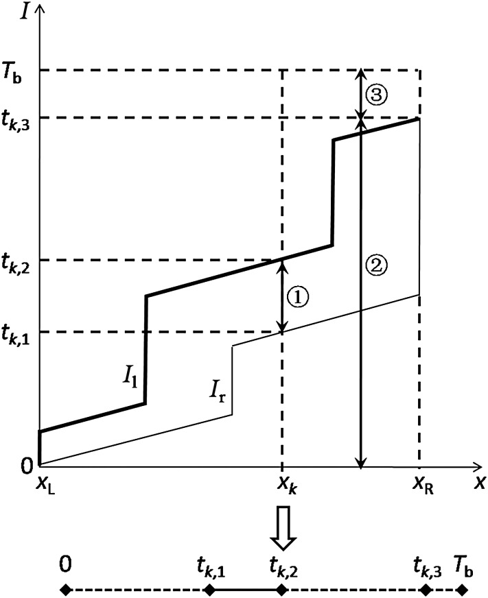
In general, the leaf trajectory is the description of the leaf positions that are correlative with the accumulated intensities (see Fig. 1). When the dose rate keeps constant during the beam delivery, the intensities can be represented in terms of time, i.e. the leaf position is correlated with time. In Fig. 1, the x-axis represents leaf position from the leaf motion starting position (xL) to the leaf motion ending position (xR), and the y-axis represents the intensity (or the time) delivered by the radiation beam. Theoretically, x and I were digitized into discrete leaf positions and intensities, respectively [18]. Then, a leaf-setting algorithm with a sliding-window approach was developed to find the intensities delivered when the left leaf and the right leaf pass the leaf position, x, such that the desired I(x) is identical to Il(x) − Ir(x).
Fig. 1.
The leaf trajectory and the corresponding vector T diagram (x-axis represents the leaf position and y-axis represents the delivered intensities). When the dose rate keeps constant during the beam delivery, the intensities can be represented in terms of time. For the leaf trajectory, Il represents the left leaf trajectory and Ir represents the right leaf trajectory.
The leaf trajectory indicated that the open aperture formed by an MLC leaf pair kept changing during DMLC–IMRT delivery. As a result, the implanted fiducial marker could not always be visible during beam delivery. Here, the concept of marker visibility V was proposed, that is, the percentage ratio of the marker visibility time (Tm) and the beam delivery time (Tb).
| (1) |
For instance, the kth marker was located at xk position (see Fig. 1). A vertical dashed line at xk was intersected by the leaf trajectory at two points that denoted the starting point (tk,1) and the ending point (tk,2) of the marker visibility interval, i.e. the kth marker could be visible from tk,1 to tk,2, and the marker visibility time was tk,2–tk,1. Additionally, the ending point of the leaf travel interval (tk,3) and the beam delivery time (Tb) could be determined directly from the leaf trajectory. Therefore, the marker visibility of the kth marker was (tk,2–tk,1)/Tb.
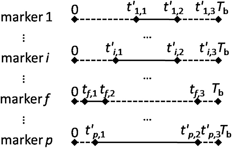
Based on the above illustrations, there were three intervals of note in Fig. 1:  was the marker visibility interval (tk,1–tk,2);
  was the leaf travel interval (0–tk,3);
  and was the interval between the endpoint of the leaf travel and the endpoint of the beam delivery (tk,3–Tb), denoted as δmax,k. The variable δ will be described in more detail later in the text.
As indicated in Fig. 1, the leaf trajectory of the kth marker can be transformed into a simplified diagram. This diagram is composed of four line segments. The solid line segment (tk,1–tk,2) represents the marker visibility interval, while the dotted line segments (0–tk,1, tk,2–tk,3 and tk,3–Tb) represent the intervals in which the marker was invisible. The length of each line segment indicates the duration from 0–tk,1, tk,1–tk,2, tk,2–tk,3, or tk,3–Tb. In particular, the length of the line segment tk,1–tk,2 is equivalent to the marker visibility time (tk,2–tk,1). Rather than the leaf trajectory, this simplified diagram will be used to illustrate the algorithm for the remainder of this paper.
Vector T
Mathematically, the diagram can be defined as vector T, where:
| (2) |
where p is the number of fiducial markers; the first and second elements, tk,1 and tk,2, are the starting and ending points of the kth marker visibility interval, respectively; and the third element, tk,3, indicates that the kth MLC leaf pair will finish its delivery at tk,3.
The whole vectors compose a matrix T (p rows by three columns), generally:
| (3) |
where each row of the matrix T is a vector T, describing the time information of the leaf trajectory marker visibility.
Visible set
Marker visibility, according to our definition, may depend on the prescribed fluence map, the implanted marker position, the beam delivery time and the leaf trajectory. In this study, the prescribed fluence map and the implanted marker position were known conditions, and a new leaf-setting algorithm (called a Delta algorithm) was proposed under the premise of maintaining the total delivered intensities (TDIs) as the initial leaf trajectory, that is, the beam delivery time was required to remain constant. Therefore, the only parameter that can be adjusted is the leaf trajectory of each active MLC leaf pair containing the implanted fiducial marker.
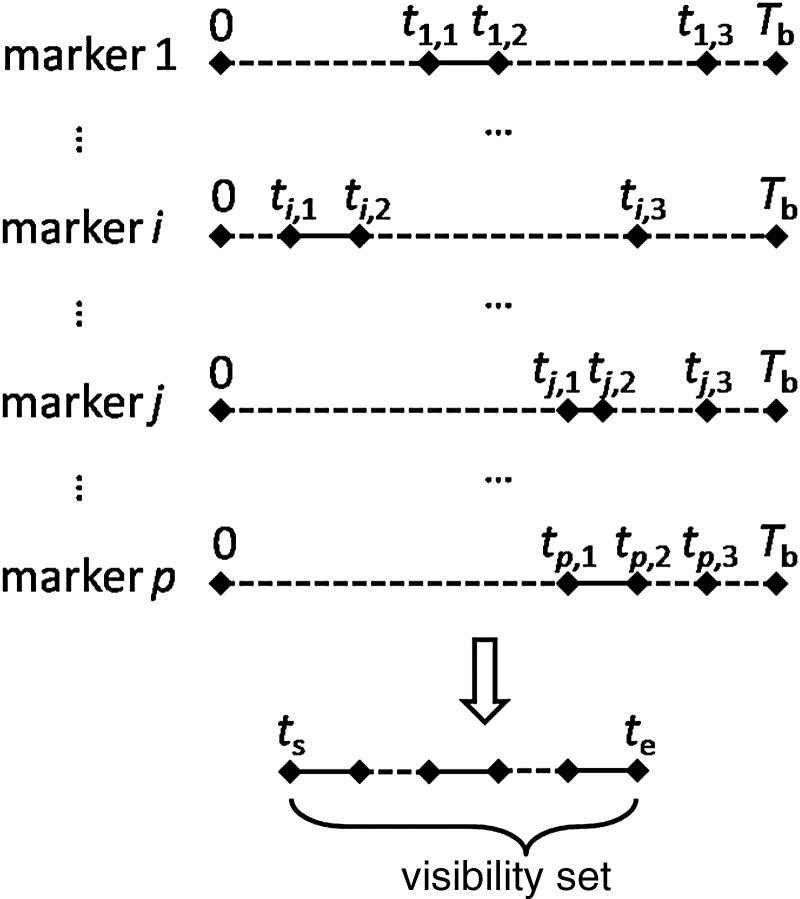
As can be seen in Fig. 2, we superposed all the vector T diagrams to form a visibility set composed of all the marker visibility intervals. The starting and ending points of the visibility set were denoted as ts and te, respectively. The total length of all solid line segments within the visibility set was the marker visibility time for these p markers. Apparently, variation in the vector T diagrams could lead to changes in the visibility set and the marker visibility time. By determining the variation in each vector T, the Delta algorithm will achieve the optimal marker visibility time as well as the optimal marker visibility.
Fig. 2.
The visible set with p markers.
Rearward movement duration
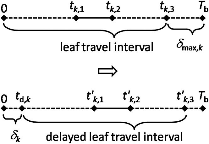
Figure 3 shows the Delta algorithm operation for a vector T. Since the interval δmax,k between the endpoint of the leaf travel and the endpoint of the beam delivery (tk,3–Tb) exists, the leaf travel interval can be rearward moved as long as δk (0 ≤ δ k ≤ δmax,k) to produce a delayed leaf travel interval (td,k–t′k,3), where td,k = δk and t′k,3 = tk,3+ δk. The notation, δ, is called the rearward movement duration in this paper, thus δmax,k is the maximal rearward movement duration of the kth marker (see Equation 4). As a result, the marker visibility interval becomes t′k,1–t′k,2, where t′k,1 = tk,1 + δk and t′k,2 = tk,2 + δk.
| (4) |
Fig. 3.
The rearward movement duration (δ) and the delayed leaf travel interval.
Optimization problem
From the above illustration, the optimization problem is equivalent to finding the optimal value of variable δ for each vector T. It is given by the following:
| (5) |
where Tm is the optimization objective. This is a constrained optimization problem (with a function of p variables) that can be written in vector form (see Equation 6). The constraint, 0 ≤ δk ≤ δmax,k, sought to ensure that the beam delivery time was kept constant. The challenge was to find an optimal vector Delta that satisfies this condition, and can be solved using our developed Delta algorithm with an analytic method.
| (6) |
Illustration of Delta algorithm
As can be seen from Fig. 2 and Fig. 3, determining the value of δk depends on the previous k − 1 values of δ that have been fixed already. So, the order of determination is important in finding the optimal value of δ. For p active MLC leaf pairs containing the fiducial marker, there are factorial p (p!) possible permutations. Each permutation determines an order of setting values for δ. For instance, the ith permutation is denoted as Pi (see Equation 7), and the corresponding δ values defined by the Delta algorithm are given by Equation 8.
| (7) |
| (8) |
From Equations 5 and 8, we know that the permutation and the marker visibility time have a ‘one-to-one’ relationship. Therefore, the Delta algorithm iterates all possible permutations so as to find the optimal corresponding marker visibility time. This is the analytical method of the Delta algorithm.
In order to illustrate this method mathematically, we defined a matrix Delta of p-rows by p!-columns. Generally,
| (9) |
| (10) |
where Δi is the ith vector Delta, and δk,i is the rearward movement duration of the kth marker for the ith permutation which can be obtained from T and Tb (see Equation 8). The marker visibility time corresponding to the permutation (each column of the matrix Delta) composes the vector Tm (see Equation 11), and then the optimal marker visibility time can be obtained (see Equation 12) so as to derive the optimal marker visibility (see Equation 13). Finally, the optimal vector Delta is obtained, including the optimal values of δ for these p leaf trajectories (see Equation 14).
| (11) |
| (12) |
| (13) |
| (14) |
Moreover, we have the optimal matrix T, which is given by:
| (15) |
or
| (16) |
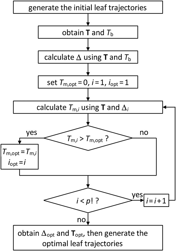
In summary, the Delta algorithm is implemented as follows. (i) Using a typical leaf-setting algorithm, generate the initial leaf trajectories [18]. (This step requires the intensity matrix.) (ii) Acquire matrix T and Tb from the initial leaf trajectories and the marker positions (see Equation 3). (This step requires the 3D coordinates of the implanted marker and the gantry angle.) (iii) Calculate matrix Delta using matrix T and Tb (see Equation 8 and 9). (iv) Find the optimal vector Delta using an iteration method, and then derive the maximal marker visibility (see Equation 11–13). (v) Generate the optimal leaf trajectories from the optimal vector Delta (see Equation 14–16). The flowchart of the Delta algorithm is given in Fig. 4 (programmed in MATLAB language).
Fig. 5.
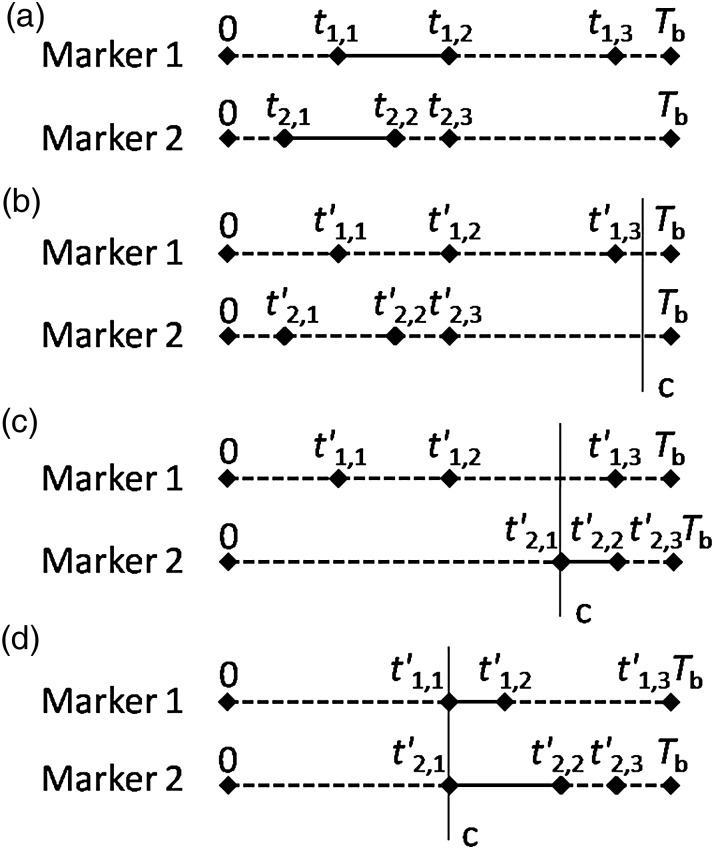
The c posterior-marker visible time: (a) the original vector T diagrams; (b) neither of the two markers was visible behind c; (c) only one of the markers was visible behind c; (d) both of the two markers were visible behind c.
Fig. 6.
The front-most marker (the marker f).
Fig. 4.
The flowchart of the Delta algorithm for a given field.
RESULTS
An example
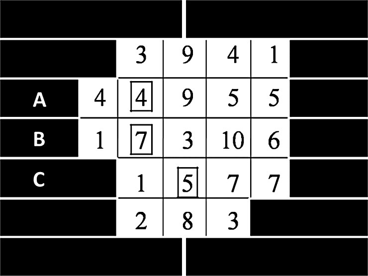
To explain how the Delta algorithm works, we took the following simple intensity matrix as an example (see Fig. 7). Five active MLC leaf pairs were used to deliver a 2D intensity profile with a maximal intensity level of 10. Here, the three markers, denoted mA, mB and mC, were located in the leaf pairs A, B and C, respectively (the markers were represented as squares in Fig. 7). We assumed that the leaf step was 0.5 cm, the dose rate was 1 intensity/s and the leaf speed was 0.5 cm/s. The implementation of Delta algorithm for this example is as follows.
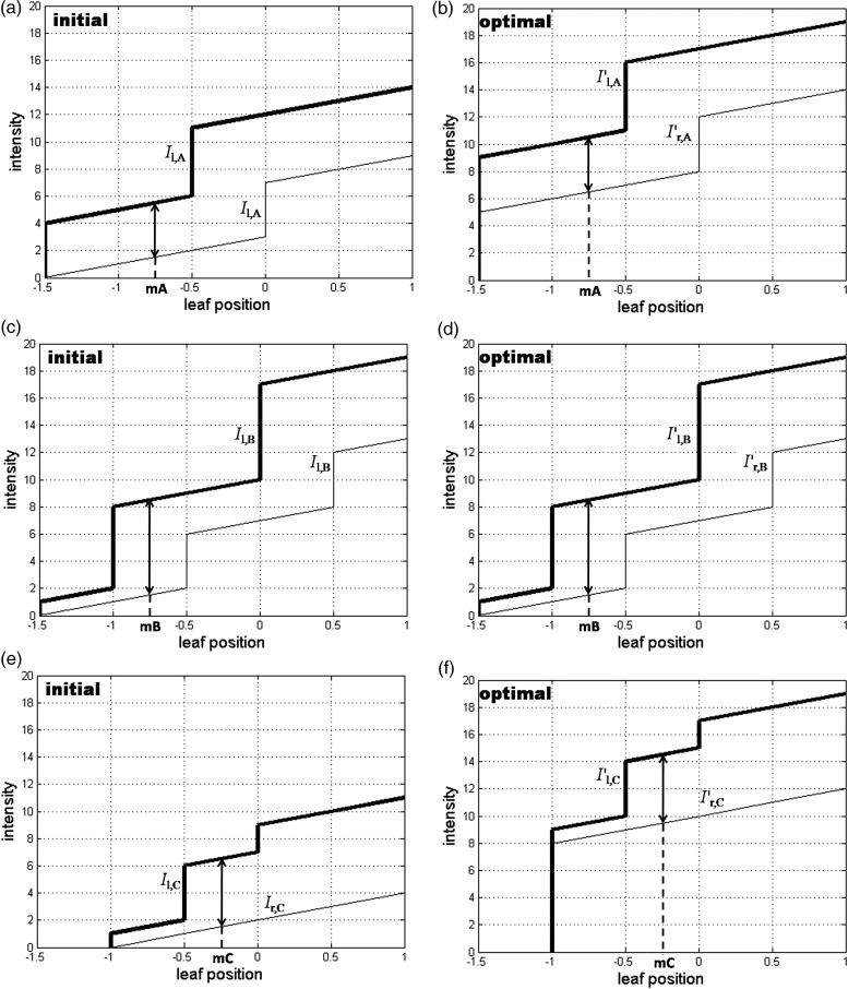
The initial leaf trajectories were generated for the leaf pairs A, B and C (see Fig. 8a, c and e).
- The matrix T was obtained from the initial leaf trajectories and the marker positions (see Equation 3). From matrix T, we knew that the marker visibility intervals were 1.5–5.5, 1.5–8.5 and 1.5–6.5 (with marker visibility times 4, 7 and 5, respectively), and the leaf travel intervals were 0–14, 0–19 and 0–11 (δmax was 5, 0 and 8) for mA, mB and mC, respectively. We also knew that the beam delivery time Tb = 19.
(17) - Based on the above T and Tb, we could derive Δ (see Equations 8 and 9):
(18) - By finding Tm,opt, the optimal Δi and T could be obtained (see also Equations 14–16):
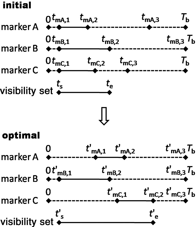
(20) (21) Optimal leaf trajectories were generated for leaf pairs A, B and C (see Fig. 8b, d and f). Compared with the initial leaf trajectories, the marker visibility time increased from 7 to 13, so the marker visibility increased from 36.84 to 68.42% (as indicated by the vector T diagrams in Fig. 9).
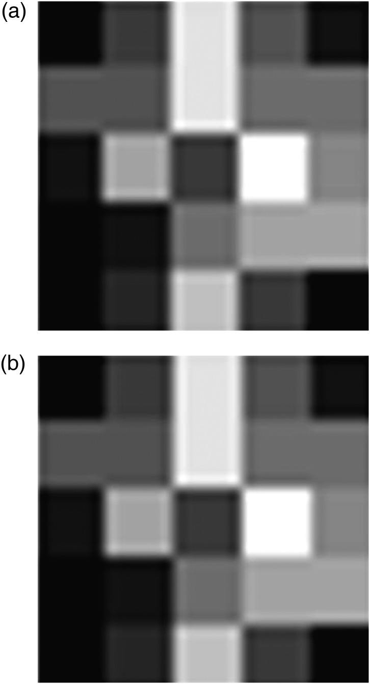
To verify the correctness of the leaf trajectories generated here, the fluence maps were recomputed for the initial and the optimal leaf trajectories (see Fig. 10). We found that the fluence map delivered by the optimal leaf trajectories was the same as the initial one, and they were identical to the desired intensity matrix. This confirmed the new leaf-setting algorithm was correct.
Fig. 7.
The desired intensity matrix was taken as an example. The three markers (mA, mB and mC) were represented as squares located in the MLC leaf pairs A, B and C, respectively.
Fig. 8.
The initial leaf trajectories generated by a typical leaf-setting algorithm for the MLC leaf pairs A, B and C ((a), (c) and (e)), and the optimal leaf trajectories generated by the Delta algorithm for the leaf pairs A, B and C ((b), (d) and (f)). The thick lines represent the left leaf pairs, and the thin lines represent the right leaf pairs (the unit for leaf position is cm).
Fig. 9.
The corresponding vector T diagrams for both initial and optimal leaf trajectories and a comparison between the two visibility sets.
Fig. 10.
The fluence map recomputed for (a) the initial and (b) the optimal leaf trajectories. Different gray scales represent the corresponding intensity levels.
Artificial fields
We evaluated the Delta algorithm performance using six randomly generated artificial fields. The intensity levels within the fields were randomly set to an integer values between 0 and 10. The characteristics of these fields were as follows: (a) small field (5 × 5) with single marker; (b) small field (the same as case (a)) with three markers; (c) medium field (10 × 10) with single marker; (d) medium field (the same as case (c)) with three markers; (e) large field (20 × 20) with single marker; (f) large field (the same as case (e)) with three markers. The marker positions within the intensity fields were randomly generated.
Table 1 shows a comparison of the results from the initial and the optimal DMLC leaf trajectories, and the optimal SMLC leaf sequences in terms of total delivered intensities (TDIs) and marker visibility. The table indicates that: (i) compared with initial results, TDIs were kept constant; (ii) compared with initial results, for the fields with a single marker, the marker visibility was unchanged for case (a), (c) and (e); for the fields with three markers, the marker visibility improved from 68.00 to 72.00%, from 38.46 to 43.59% and from 28.57 to 37.14% for case (b), (d) and (f), respectively; (iii) compared with SMLC mode, TDIs with DMLC mode increase 25.00% for the small field, 34.48% for the medium field and 40.00% for the large field; (iv) compared with SMLC mode, marker visibility decreased 20.00%, 28.00%, 25.66%, 47.33%, 28.58% and 33.68 for cases (a–f), respectively.
Table 1.
Evaluation of Delta algorithm performance for artificial fields
| Case | Field size | Number of markers | Total delivered intensities |
Marker visibility (%) |
||||
|---|---|---|---|---|---|---|---|---|
| Initial | Optimal | Optimal (SMLC) | Initial | Optimal | Optimal (SMLC) | |||
| a | 5 × 5 | 1 | 25 | 25 | 20 | 32.00 | 32.00 | 40.00 |
| b | 5 × 5 | 3 | 25 | 25 | 20 | 68.00 | 72.00 | 100 |
| c | 10 × 10 | 1 | 39 | 39 | 29 | 20.51 | 20.51 | 27.59 |
| d | 10 × 10 | 3 | 39 | 39 | 29 | 38.46 | 43.59 | 82.76 |
| e | 20 × 20 | 1 | 70 | 70 | 50 | 8.57 | 8.57 | 12.00 |
| f | 20 × 20 | 3 | 70 | 70 | 50 | 28.57 | 37.14 | 56.00 |
Clinical fields
We also evaluated the Delta algorithm performance using 15 clinical fields from 5-field IMRT plans (at angles of 225o, 285o, 0o, 75o and 135o) for three prostate cancer patients with three implanted fiducial markers. The fluence maps of these fields were exported from the Philips Pinnacle3 treatment-planning system with a beamlet size of 0.5 × 0.5 cm2. The marker positions were determined from the CT images obtained from Memorial Sloan Kettering Cancer Center (MSKCC, New York, USA).
Table 2 shows a comparison of the results from the initial and the optimal DMLC leaf trajectories with the optimal SMLC leaf sequences, in terms of TDIs and marker visibility. This table indicates that: (i) compared with initial results, TDIs were kept constant; (ii) compared with initial results, marker visibility improved for 10 fields (increased 6–10% for three fields, 10–20% for four fields, 20–30% for one field and > 50% for two fields), but was unchanged for the other five fields; (iii) compared with SMLC mode, TDIs with DMLC mode increases 123.08–218.18% for the 15 fields; (iv) compared with SMLC mode, marker visibility with DMLC mode decreased 18.93–89.95% for the 15 fields.
Table 2.
Evaluation of Delta algorithm performance for clinical fields
| Case | Field size | Total delivered intensities |
Marker visibility (%) |
|||||
|---|---|---|---|---|---|---|---|---|
| Initial | Optimal | Optimal (SMLC) | Initial | Optimal | Optimal (SMLC) | |||
| Patient 1 | Beam 1 | 22 × 19 | 28 | 28 | 10 | 39.29 | 39.29 | 100 |
| Beam 2 | 22 × 19 | 30 | 30 | 11 | 31.33 | 33.33 | 100 | |
| Beam 3 | 22 × 22 | 39 | 39 | 17 | 28.21 | 33.33 | 70.59 | |
| Beam 4 | 22 × 18 | 30 | 30 | 12 | 28.67 | 28.67 | 100 | |
| Beam 5 | 22 × 20 | 29 | 29 | 10 | 42.07 | 45.52 | 90.00 | |
| Patient 2 | Beam 1 | 20 × 19 | 29 | 29 | 10 | 28.97 | 31.72 | 60.00 |
| Beam 2 | 20 × 16 | 29 | 29 | 13 | 26.90 | 31.72 | 92.31 | |
| Beam 3 | 20 × 22 | 38 | 38 | 17 | 26.32 | 31.58 | 76.47 | |
| Beam 4 | 20 × 16 | 26 | 26 | 10 | 27.69 | 35.38 | 100 | |
| Beam 5 | 20 × 17 | 26 | 26 | 10 | 49.23 | 49.23 | 100 | |
| Patient 3 | Beam 1 | 22 × 25 | 35 | 35 | 11 | 22.29 | 36.57 | 63.64 |
| Beam 2 | 21 × 24 | 37 | 37 | 13 | 5.41 | 5.41 | 53.85 | |
| Beam 3 | 23 × 23 | 38 | 38 | 15 | 25.26 | 25.26 | 80.00 | |
| Beam 4 | 22 × 24 | 38 | 38 | 14 | 11.58 | 28.95 | 35.71 | |
| Beam 5 | 23 × 24 | 43 | 43 | 19 | 25.58 | 29.77 | 100 | |
DISCUSSION
A number of leaf-setting algorithms have been developed to deliver arbitrary beam intensity profiles for 3D IMRT. For future 4D RT planning, the additional dimension ‘time’ has been considered in several approaches, such as ITV margins, deformable registration and probability distributions, but these approaches require knowledge of the target motion in advance. Although 4D CT is an acceptable solution, real-time tracking with implanted fiducial markers is preferable because of discrepancies in the target motion pattern between CT simulation and treatment delivery. For real-time tracking radiotherapy, the primary requirement is that the fiducial markers are visible as long as possible on EPID so as to ensure the tracking effectiveness. In this study, we have proposed a new leaf-setting algorithm (a Delta algorithm) that determines marker visibility in order to minimize blocking of the fiducial markers by the MLC leaf pairs. This is unique compared with other leaf-setting algorithms.
By adjusting the initial leaf trajectories, the Delta algorithm can generate the optimal leaf trajectories with maximal marker visibility while keeping the beam delivery time constant. Its correctness has been verified by an intensity matrix example. To evaluate the feasibility of the Delta algorithm, six randomly generated artificial fields and 15 clinical fields were used. For the artificial fields, marker visibility increased for cases b, d and f (fields with three markers), while keeping the TDIs constant. But for fields with a single marker, marker visibility was unchanged because the marker visibility time could not be prolonged for a single leaf pair (the intensity level of the beamlet where the marker location was fixed). For the clinical fields, marker visibility increased for 10 fields, but was unchanged for the other five fields. It should be stressed that the optimization objective of the Delta algorithm is to maximize marker visibility, but not to improve it. If the marker visibility of the initial solution has the same value as the theoretical maximum, the optimal solution cannot increase the marker visibility.
Based on the definition of marker visibility and the performance evaluation results, the value of marker visibility appears to depend on the number of fiducial markers, the field size and the TDIs. Tables 1 and 2 indicate that, generally: (i) the greater the number of markers, the larger the marker visibility; (ii) the bigger the field size and the greater the TDIs, the lower the marker visibility; (iii) DMLC–IMRT needs to deliver much greater intensities than SMLC–IMRT to obtain the same fluence map. Consequently, marker visibility would be decreased with DMLC mode. It has been suggested that implanting more fiducial markers might be favorable for tracking, but in practice this would increase the discomfort and side-effects for patients. It has also been suggested that increasing the complexity of the field might lower the tracking effectiveness.
The computational efficiency was also evaluated by our study. Obviously, the CPU time depends on the scale of the optimization problem. For a given field from the artificial and clinical fields in this paper, it took < 0.1 s for Delta algorithm optimization (Intel 2.83 GHz Quad CPU, 4 GB memory). Consequently, the computational efficiency was sufficient to integrate the Delta algorithm into a 4D treatment-planning system as a functional module in the future.
Furthermore, in this work, we proposed several concepts to illustrate the algorithm, such as marker visibility, marker visibility interval, leaf travel interval and rearward movement duration (δ). These concepts are theoretical fundamentals on which to base future studies of 4D DMLC tracking radiotherapy.
However, the proposed algorithm also has scope for improvement. The first issue to consider is marker movement during irradiation. A feasible solution would be to combine this study with the published DMLC tracking technique [13, 14]. By using the DMLC tracking, the implanted marker is ‘static’ relative to the radiation field. From there, we could achieve improved marker visibility using the Delta algorithm. The second issue is to determine the marker visibility contribution for the preset optimization parameters, such as intensity level, leaf gap, EPID image sets (frame speed) and so on. Because this paper was a theoretical study, the Delta algorithm could improve on the ‘theoretical’ marker visibility using the computer. Research into improving ‘practical’ marker visibility now needs to be carried out.
A new leaf-setting algorithm has been developed to generate leaf trajectories for DMLCs with maximal marker visibility. In this work, we have described several concepts to illustrate the algorithm, and these concepts are theoretical fundamentals on which to base future studies of 4D DMLC tracking radiotherapy. By determining the value of δ for each MLC leaf pair, the Delta algorithm can yield optimal leaf trajectories with maximal marker visibility while still keeping the beam delivery time constant. The implementation of the Delta algorithm has been achieved using analytical methods, and the optimality has been proven mathematically. The correctness of the Delta algorithm has been verified using an example of a 2D intensity profile, and its feasibility has been evaluated using six randomly generated artificial fields and 15 clinical fields. Evaluation of the results has indicated that the Delta algorithm can improve marker visibility without increasing TDIs. Furthermore, the computational efficiency is sufficient for integrating the Delta algorithm into a 4D treatment planning system as a functional module in the future.
FUNDING
Funding to pay the Open Access publication charges for this article was provided by National Natural Science Foundation of China [Grant No. 10975187].
ACKNOWLEDGEMENTS
We gratefully thank C. Clifton Ling (Memorial Sloan Kettering Cancer Center, New York, USA) for the prostate CT images.
APPENDIX
Mathematical proofs of optimality
Firstly, we introduced some concepts for the following proofs: 1) feasible vector Delta; 2) eigenvector Delta; 3) c posterior-marker visible time; 4) front-most marker.
Feasible vector Delta: the fact that Δ = (δ1, …, δp)T is feasible requires: δi ≥ 0 and δi ≤ Tb-ti,3, i = 1, …, p.
Eigenvector Delta: the eigenvector ΔE = (δE1, …, δEp)T satisfies that there exists δEi = 0, i = 1, …, p.
c posterior-marker visible time: for an arbitrary constant c > 0, it is supposed that the marker is not visible when it appears ahead of c, then the marker visible time is called c posterior-marker visible time. If c posterior-marker visible time is taken as the optimization objective, Delta algorithm only considers the markers that could be c posterior-visible (see Fig. 5). For instance, the vector T diagrams of two markers are shown in Fig. 5(a), there are three cases when introducing c posterior-marker visible time: 1) neither of the two markers could be visible behind c (see Fig. 5(b)), that is, t1,2 + (Tb-t1,3) ≤ c and t2,2 + (Tb-t2,3) ≤ c; 2) only one of the markers could be visible behind c (see Fig. 5(c)), that is, t2,2 + (Tb-t2,3) > c but t1,2 + (Tb-t1,3) ≤ c (or t1,2 + (Tb-t1,3) > c but t2,2 + (Tb-t2,3) ≤ c). In this case, the Marker 2 could be regarded as a new marker with t'2,1 = c and t'2,2 = min(t2,2 + (Tb-t2,3), t2,2 + c-t2,1) for Delta algorithm optimization; 3) both of the two markers could be visible behind c (see Fig. 5(d)), that is, t1,2 + (Tb-t1,3) > c and t2,2 + (Tb-t2,3) > c. In this case, both of the markers could be regarded as new markers with t'1,1 = c, t'1,2 = min(t1,2 + (Tb-t1,3), t1,2 + c-t1,1), t'2,1 = c and t'2,2 = min(t2,2 + (Tb-t2,3), t2,2 + c-t2,1) for Delta algorithm optimization.
Front-most marker: the marker satisfies ti,1 + (Tb-ti,3) ≥ tf,1 for all i ≠ f, when δf = 0. The example of a front-most marker, the fth marker, is shown in Fig. 6.
Next, we established theorems to demonstrate the optimality of Delta algorithm.
Lemma 1: for Δ = (δ1, …, δp)T, the marker visible time is Tm. For an arbitrary constant c > 0, if Δ' = Δ ± c = (δ1 ± c, …, δp ± c)T is feasible, then Tm' = Tm.
Proofs.
For Δ = (δ1, …, δp)T, supposed that the visible set is from ts to te. For Δ' = Δ ± c = (δ1 ± c, …, δp ± c)T, the positions of ts and te are changed, ts' = ts ± c, te' = te ± c, but the durations and the relative positions of all visible intervals within the visible set are not changed. So, we have Tm' = Tm.
Therefore, for an arbitrary constant c > 0, if Δ' = Δ ± c = (δ1 ± c, …, δp ± c)T is feasible, then Tm' = Tm.
Theorem 1: for Δ = (δ1, …, δp)T, the marker visible time is Tm. Then there exists an eigenvector ΔE, satisfies Tm,E = Tm.
Proofs.
For Δ = (δ1, …, δp)T, if there exists δi = 0, this theorem is proved. If there does not exist δi = 0, then we have δ1, …, δp > 0, and δmin = min(δ1, …, δp). Let ΔE = (δE,1, …, δE,p)T = Δ-δmin = (δ1-δmin, …, δp-δmin)T, then we have δE,min = 0. According to lemma 1, we have Tm,E = Tm, so the theorem is proved.
Therefore, there exists an eigenvector ΔE, satisfies Tm,E = Tm.
Theorem 2: for two markers, Delta algorithm is optimal in terms of marker visible time.
Proofs.
According to Delta algorithm, Δ1 = (δ1,1, δ2,1)T when the permutation P1 = (1, 2), where δ1,1 = 0 and δ2,1 = min{|min[(t2,1-t1,2), 0]|, Tb-t2,3}, the marker visible time is Tm,1; when P2 = (2, 1), Δ2 = (δ1,2, δ2,2)T, where δ1,2 = min{|min[(t1,1-t2,2), 0]|, Tb-t1,3} and δ2,2 = 0, the marker visible time is Tm,2. Then, for this two markers, the marker visible time obtained by Delta algorithm is Tm,Delta = max(Tm,1, Tm,2).
There have 3 cases:
t1,2 ≤ t2,1 (or t2,2 ≤ t1,1)
Obviously, the optimal marker visible time is Tm,opt = (t1,2-t1,1) + (t2,2-t2,1). Since t1,2 ≤ t2,1, we have δ1,1 = δ2,1 = 0. So, Tm,1 = (t1,2-t1,1) + (t2,2-t2,1). We also have δ1,2 ≥ 0 and δ2,2 = 0. So, Tm,2 ≤ (t1,2-t1,1) + (t2,2-t2,1). Consequently, Tm,Delta = max(Tm,1, Tm,2) = (t1,2-t1,1) + (t2,2-t2,1) = Tm,opt. Therefore, Delta algorithm is optimal in this case.
t1,1 < t2,1 < t1,2 < t2,2 (or t2,1 < t1,1 < t2,2 < t1,2)
Since t1,1 < t2,1 < t1,2 < t2,2, we have δ1,1 = 0 and δ2,1 = min(t1,2-t2,1, Tb-t2,3). So, Tm,1 = (t2,2-t1,1) + δ2,1. We also have δ2,2 = 0 and δ1,2 = min(t2,2-t1,1, Tb-t1,3). So, Tm,2 = (t2,2-t2,1) + max(t2,1-t1,1-δ1,2, 0) + max(t1,2 + δ1,2-t2,2, 0).
If Tm,1 ≥ Tm,2, then Tm,Delta = (t2,2-t1,1) + δ2,1.
Reduction to absurdity:
Supposed that there exists Δ = (δ1, δ2)T, satisfies Tm,Δ > Tm,Delta. Let ΔE = (δE1, δE2)T be its eigenvector. According to theorem 1, we have Tm,ΔE = Tm,Δ > Tm,Delta. There are 2 cases here:
δE1 = 0
Here, Tm,ΔE = (t2,2-t1,1) + δE2-max(t2,1 + δE2-t1,2, 0). Since Tm,ΔE > Tm,Delta, so we have (t2,2-t1,1) + δE2-max(t2,1 + δE2-t1,2, 0) > (t2,2-t1,1) + δ2,1, that is, δE2 > min(t1,2-t2,1, Tb-t2,3) + max(δE2-(t1,2-t2,1), 0). If δE2 > t1,2-t2,1, we have δ2,1 < 0, false! If δE2 ≤ t1,2-t2,1, we have δE2 > min(t1,2-t2,1, Tb-t2,3) and Tb-t2,3 ≥ δE2, false! Consequently, there does not exist Δ satisfies Tm,Δ > Tm,Delta, that is, Delta algorithm is optimal in this case.
δE2 = 0, the theorem can be proved similarly.
If Tm,1 < Tm,2, the theorem can be proved similarly.
t1,1 ≤ t2,1 and t2,2 ≤ t1,2 (or t2,1 ≤ t1,1 and t1,2 ≤ t2,2)
Since t1,1 ≤ t2,1 and t2,2 ≤ t1,2, we have δ1,1 = 0 and δ2,1 = min(t1,2-t2,1, Tb-t2,3). So, Tm,1 = (t1,2-t1,1) + max(t2,2 + δ2,1-t1,2, 0). We also have δ2,2 = 0 and δ1,2 = min(t2,2-t1,1, Tb-t1,3). So, Tm,2 = (t1,2-t1,1) + max(t1,1 + δ1,2-t2,1, 0).
If Tm,1 ≥ Tm,2, then Tm,Delta = (t1,2-t1,1) + max(t2,2 + δ2,1-t1,2, 0).
Reduction to absurdity:
Supposed that there exists Δ = (δ1, δ2)T, satisfies Tm,Δ > Tm,Delta. Let ΔE = (δE1, δE2)T be its eigenvector. According to theorem 1, we have Tm,ΔE = Tm,Δ > Tm,Delta. There are 2 cases here:
δE1 = 0
Here, Tm,ΔE = (t1,2-t1,1) + max(t2,2 + δE2-t1,2, 0)-max(t2,1 + δE2-t1,2, 0). Since Tm,ΔE > Tm,Delta, so we have (t1,2-t1,1) + max(t2,2 + δE2-t1,2, 0)-max(t2,1 + δE2-t1,2, 0) > (t1,2-t1,1) + max(t2,2 + δ2,1-t1,2, 0), that is, δE2 > max(δE2-(t1,2-t2,1), 0) + max(min(t1,2-t2,1, Tb-t2,3), (t1,2-t2,2)). If t1,2-t2,1 > Tb-t2,3, then δE2 > Tb-t2,3, false! If t1,2-t2,1 ≤ Tb-t2,3, then δE2 > max(δE2, t1,2-t2,1), false! Consequently, there does not exist Δ satisfies Tm,Δ > Tm,Delta, that is, Delta algorithm is optimal in this case.
δE2 = 0, the theorem can be proved similarly.
If Tm,1 < Tm,2, the theorem can be proved similarly.
So, Delta algorithm is optimal in this case.
Therefore, for two markers, Delta algorithm is optimal in terms of marker visible time.
Corollary 1: for two markers, Delta algorithm is optimal in terms of c posterior-marker visible time. According to theorem 2 and the concept of c posterior-marker visible time, obviously, the corollary 1 is established.
Theorem 3: for p markers, Delta algorithm is optimal in terms of marker visible time. Proofs.
Mathematical induction:
When p = 1, theorem 3 is proved.
When p = 2, according to theorem 2, theorem 3 is proved.
Supposed that theorem 3 is proved when p = 3, …, k. According to corollary 1 and its proofs, we know that, for k markers, Delta algorithm is optimal in terms of c posterior-marker visible time. The following is the proofs of theorem 3 when p = k + 1.
For an arbitrary ΔE = (δE1, …, δEk+1)T, the marker visible time is Tm,ΔE. Let t'f,1 = min(t'1,1, …, t'k+1,1), t'f,1= tf,1 + δEf. Then the fth marker is a front-most marker. Let c = t'f,2, then, for the other k markers (not including the fth marker), Delta algorithm is optimal in terms of c posterior-marker visible time, that is, Tm,Delta,c post ≥ Tm,ΔE,c post. Let δf = 0, we have Tm,Delta,δf = 0 ≥ Tm,ΔE for these k + 1 markers, that is, we can find a front-most marker satisfies Tm,Delta,δf = 0 ≥ Tm,ΔE for an arbitrary ΔE. Supposed that there are q front-most markers among these k + 1 markers. According to the concept of front-most marker and the above proofs, we have q ≥ 1 and Tm,opt = max(Tm,Delta,δf1=0, …, Tm,Delta,δfq = 0), that is, Delta algorithm is optimal when p = k + 1. Consequently, theorem 3 is proved when p = k + 1.
Therefore, for p markers, Delta algorithm is optimal in terms of marker visible time.
REFERENCES
- 1.Seppenwoolde Y, Shirato H, Kitamura K, et al. Precise and real-time measurement of 3D tumor motion in lung due to breathing and heartbeat, measured during radiotherapy. Int J Radiat Oncol. 2002;53:822–34. doi: 10.1016/s0360-3016(02)02803-1. [DOI] [PubMed] [Google Scholar]
- 2.Jensen HR, Hansen O, Hjelm-Hansen M, et al. Inter- and intrafractional movement of the tumour in extracranial stereotactic radiotherapy of NSCLC. Acta Oncol. 2008;47:1432–37. doi: 10.1080/02841860802251567. [DOI] [PubMed] [Google Scholar]
- 3.Kupelian P, Willoughby T, Mahadevan A, et al. Multi-institutional clinical experience with the Calypso system in localization and continuous, real-time monitoring of the prostate gland during external radiotherapy. Int J Radiat Oncol. 2007;67:1088–98. doi: 10.1016/j.ijrobp.2006.10.026. [DOI] [PubMed] [Google Scholar]
- 4.Gottlieb KL, Hansen CR, Hansen O, et al. Investigation of respiration induced intra- and inter-fractional tumor motion using a standard Cone Beam CT. Acta Oncol. 2010;49:1192–8. doi: 10.3109/0284186X.2010.498834. [DOI] [PubMed] [Google Scholar]
- 5.Månsson Haskå T, Honore H, Muren LP, et al. Intrafraction changes of prostate position and geometrical errors studied by continuous electronic portal imaging. Acta Oncol. 2008;47:1351–7. doi: 10.1080/02841860802256509. [DOI] [PubMed] [Google Scholar]
- 6.Berbeco RI, Pope CJ, Jiang SB. Measurement of the interplay effect in lung IMRT treatment using EDR2 films. J Appl Clin Med Phys. 2006;7:1–10. doi: 10.1120/jacmp.v7i4.2222. [DOI] [PMC free article] [PubMed] [Google Scholar]
- 7.Liu HH, Balter P, Tutt T, et al. Assessing respiration-induced tumor motion and internal target volume using four-dimensional computed tomography for radiotherapy of lung cancer. Int J Radiat Oncol. 2007;68:531–40. doi: 10.1016/j.ijrobp.2006.12.066. [DOI] [PubMed] [Google Scholar]
- 8.Korreman SS, Juhler-Nøttrup T, Persson GF, et al. The role of image guidance in respiratory gated radiotherapy. Acta Oncol. 2008;47:1390–6. doi: 10.1080/02841860802282786. [DOI] [PubMed] [Google Scholar]
- 9.Wink NM, Chao M, Antony J, et al. Individualized gating windows based on four-dimensional CT information for respiration-gated radiotherapy. Phys Med Biol. 2008;53:165–74. doi: 10.1088/0031-9155/53/1/011. [DOI] [PubMed] [Google Scholar]
- 10.Lee L, Ma YZ, Ye YY, et al. Conceptual formulation on four-dimensional inverse planning for intensity modulated radiation therapy. Phys Med Biol. 2009;54:N255–66. doi: 10.1088/0031-9155/54/13/N01. [DOI] [PMC free article] [PubMed] [Google Scholar]
- 11.Buzurovic I, Huang K, Yu Y, et al. A robotic approach to 4D real-time tumor tracking for radiotherapy. Phys Med Biol. 2011;56:1299–318. doi: 10.1088/0031-9155/56/5/005. [DOI] [PubMed] [Google Scholar]
- 12.Tacke M, Nill S, Oelfke U. Real-time tracking of tumor motions and deformations along the leaf travel direction with the aid of a synchronized dynamic MLC leaf sequencer. Phys Med Biol. 2007;52:505–12. doi: 10.1088/0031-9155/52/22/N01. [DOI] [PubMed] [Google Scholar]
- 13.Papiez L. DMLC leaf-pair optimal control of IMRT delivery for a moving rigid target. Med Phys. 2004;31:2742–54. doi: 10.1118/1.1779358. [DOI] [PubMed] [Google Scholar]
- 14.McQuaid D, Webb S. IMRT delivery to a moving target by dynamic MLC tracking: delivery for targets moving in two dimensions in the beam's eye view. Phys Med Biol. 2006;51:4819–39. doi: 10.1088/0031-9155/51/19/007. [DOI] [PubMed] [Google Scholar]
- 15.Poulsen PR, Cho B, Sawant A, et al. Dynamic MLC tracking of moving targets with a single kV imager for 3D conformal and IMRT treatments. Acta Oncol. 2010;49:1092–100. doi: 10.3109/0284186X.2010.498438. [DOI] [PubMed] [Google Scholar]
- 16.Zimmerman J, Korreman S, Persson G, et al. DMLC motion tracking of moving targets for intensity modulated arc therapy treatment: a feasibility study. Acta Oncol. 2009;48:245–50. doi: 10.1080/02841860802266722. [DOI] [PubMed] [Google Scholar]
- 17.D'Souza WD, Malinowski KT, Van Liew S, et al. Investigation of motion sickness and inertial stability on a moving couch for intra-fraction motion compensation. Acta Oncol. 2009;48:1198–203. doi: 10.3109/02841860903188668. [DOI] [PMC free article] [PubMed] [Google Scholar]
- 18.Kamath S, Sahni S, Palta J, et al. Algorithms for optimal sequencing of dynamic multileaf collimators. Phys Med Biol. 2004;49:33–54. doi: 10.1088/0031-9155/49/1/003. [DOI] [PubMed] [Google Scholar]
- 19.Ma LJ, Boyer AL, Xing L, et al. An optimized leaf-setting algorithm for beam intensity modulation using dynamic multileaf collimators. Phys Med Biol. 1998;43:1629–43. doi: 10.1088/0031-9155/43/6/019. [DOI] [PubMed] [Google Scholar]
- 20.Ma LJ, Boyer AL, Ma CM, et al. Synchronizing dynamic multileaf collimators for producing two-dimensional intensity-modulated fields with minimum beam delivery time. Int J Radiat Oncol. 1999;44:1147–54. doi: 10.1016/s0360-3016(99)00121-2. [DOI] [PubMed] [Google Scholar]
- 21.Wiersma RD, Mao W, Xing L. Combined kV and MV imaging for real-time tracking of implanted fiducial markers. Med Phys. 2008;35:1191–8. doi: 10.1118/1.2842072. [DOI] [PMC free article] [PubMed] [Google Scholar]
- 22.Mao WH, Riaz N, Lee L, et al. A fiducial detection algorithm for real-time image guided IMRT based on simultaneous MV and kV imaging. Med Phys. 2008;35:3554–64. doi: 10.1118/1.2953563. [DOI] [PMC free article] [PubMed] [Google Scholar]
- 23.Park SJ, Ionascu D, Hacker F, et al. Automatic marker detection and 3D position reconstruction using cine EPID images for SBRT verification. Med Phys. 2009;36:4536–46. doi: 10.1118/1.3218845. [DOI] [PubMed] [Google Scholar]
- 24.Zhao B, Dai JR, Ling CC. Considering marker visibility during leaf sequencing for segmental intensity-modulated radiation therapy. Med Phys. 2009;36:3906–16. doi: 10.1118/1.3177313. [DOI] [PubMed] [Google Scholar]
- 25.Ma YZ, Lee L, Keshet O, et al. Four-dimensional inverse treatment planning with inclusion of implanted fiducials in IMRT segmented fields. Med Phys. 2009;36:2215–21. doi: 10.1118/1.3121425. [DOI] [PMC free article] [PubMed] [Google Scholar]


