

Introduction
Knee imaging at 3T offers advantages over 1.5T in that the greater spatial resolution and higher SNR enhance the ability to make diagnoses of critical knee structures, such as menisci, the cruciate ligaments, and articular cartilage [1]. However, current commercial knee coils are susceptible to pulsation/flow artifacts since the blood flows primarily in the S-I direction. Therefore, multiple rows of elements in the S-I direction are preferred, to allow for phase encoding in the S-I direction [2]. Furthermore, by using a local transmit coil, it requires a less transmit power compared with a case where a whole body transmit coil is employed. This approach enables more advanced, rigorous and fast imaging applications (e.g., collecting more slices within a short acquisition time) that would have been limited or disabled by SAR limit if the whole body transmit coil were used. In addition, the local transmit coil avoids wraparound artifacts often present in the whole body transmit coil case. In earlier work, increasing the number of channels while providing two rows of elements in the S-I direction showed a clear improvement in the artifact with a parallel-imaging acceleration factor of two [1]. However, SNR at the center was significantly lower than a commercially available knee coil [1]. Now, a 15-channel knee coil has been developed that utilizes three rows of elements in the S-I direction, which allows for 3D parallel imaging while providing high SNR and good uniformity with a larger coil inner diameter.
Methods
The transmit and 15-channel receive knee array coil consists of anterior and posterior halves. The posterior consists of five complete rectangular elements, the anterior consists of four complete elements, and the remaining six elements span both halves. All of the elements are overlapped in a continuous array and overlaps are optimized to minimize coupling between neighboring elements. The element layout is given in the schematic representation (Fig. 2), and consists of three rows in the S-I direction such that the knee anatomy is centered on the middle row. This configuration provides improved SNR at the center by moving the element overlap area away from the center. Limited available space presents technical challenges in engineering a knee coil with a local 12-rung birdcage transmitter and a high number of receive channels. The inner diameter of the 15-channel coil is larger than that of the commercial 8-channel coil by a few cm at the center. Within a limited space constrained by the patient table and the requirement to provide patient comfort, the coil wall thickness to house all the necessary electronics and components is constrained to be 5cm. To overcome these constraints, several techniques are applied, including using miniature low noise pre-amplifiers (approximately 1cm3) [3] and maximizing the use of PCBs to eliminate the cables. The Siemens Trio TIM 3T MRI system was used for testing. SNR and uniformity were evaluated using a healthy volunteer. A commercially available 8-channel hybrid knee coil was evaluated in the same manner for comparison.
Figure 2.
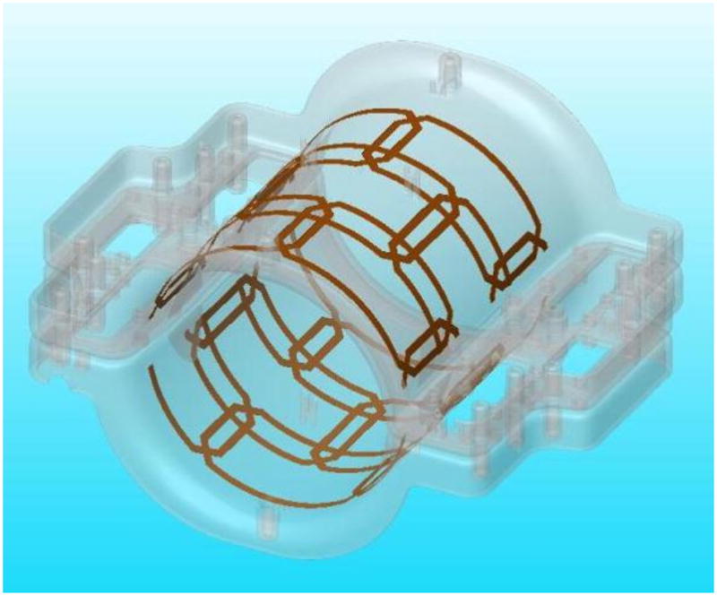
Receive element arrangement with 3 rows in the S-I direction.
Results
The 15-channel coil provides larger FOV coverage in the S-I direction, and despite of the fact that the 15-channel coil has a larger inner diameter, the high clinical image quality obtained is comparable with that of the commercial 8-channel array coil (Fig. 3). The 15-channel also provides parallel-imaging capability in the S-I direction, which is not available with the commercial coil, with no noticeable flow artifact (Fig. 4).
Fig 3.
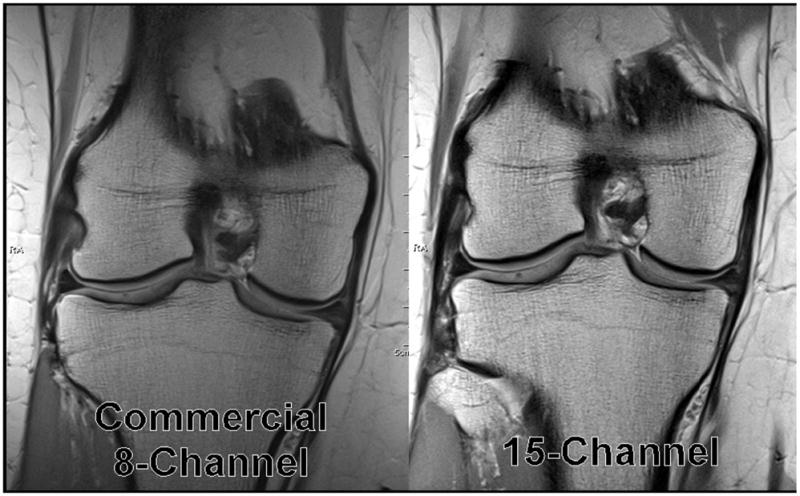
MR images from volunteer with the 15-channel coil and the commercially available 8-channel coil.
Figure 4.
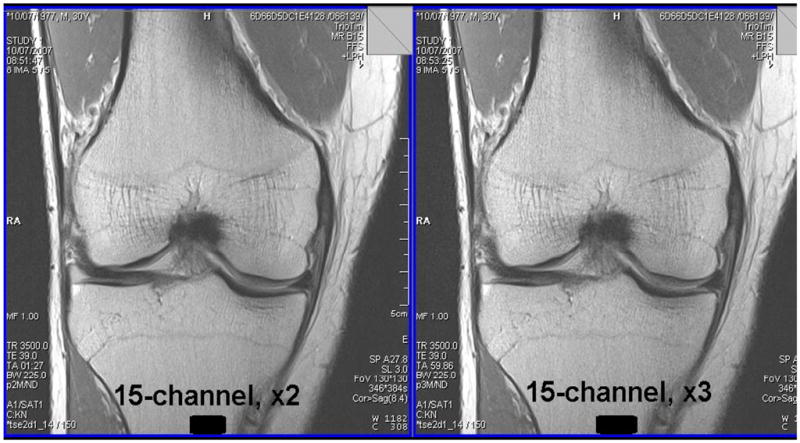
15-channel knee coil with parallel imaging in S-I direction, acceleration factor of 2 (left) and 3 (right).
Conclusion
A 15-channel knee coil has been developed for knee imaging at 3T that uses three rows of elements in the S-I direction to allow for parallel imaging in all directions with high SNR and good uniformity. The addition of parallel-imaging capability in the S-I direction allows for faster scan times, which is advantageous for patient comfort and in suppressing motion artifacts. It also reduces the flow artifact along the leg by allowing the phase encoding to be in the S-I direction.
Figure 1.
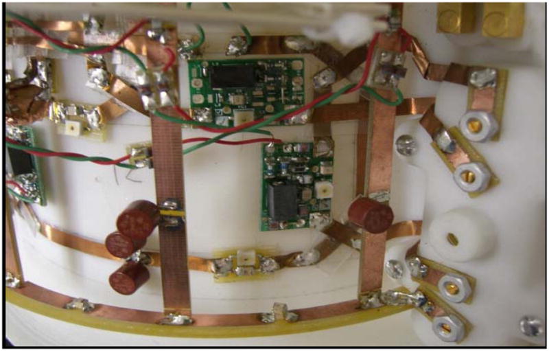
Photograph of a section of the coil.
Acknowledgments
The authors thank Dr. Hubertus Fischer, Wolfgang Risse and Wolfgang Goetz at Siemens Medical Solutions (Erlangen, Germany) for their invaluable support and discussions. The authors would also like to thank Drs. Mark Griswold, Mark Robbin, Jeff Sunshine, and Jeff Duerk at University Hospitals of Cleveland for their invaluable support and discussions. This work was also supported in part by the National Institutes of Health (grant 1 R43 EB007094-01A2).
References
- 1.Ramnath R. 3T MR Imaging of the Musculoskeletal System (Part II): Clinical Applications. Magnetic Resonance Imaging Clinics of North America: 3T MR Imaging. 2006;14(1):41–45. doi: 10.1016/j.mric.2006.01.003. [DOI] [PubMed] [Google Scholar]
- 2.Yang X, et al. A 3D Parallel Imaging Capable Transmit and 16-Channel Receive Array Knee Coil at 3T. Proc Intl Soc Mag Reson Med. 2007;15:1038. [PMC free article] [PubMed] [Google Scholar]
- 3.Fujita H, et al. A 3T Head Transmitter Integrated with 3D Parallel Imaging Capable 16-Channel Receive Array Coil. Proc Intl Soc Mag Reson Med. 2007;15:3254. [Google Scholar]