Abstract
An Optical Projection Tomography (OPT) system was developed and optimized to image 3D tissue engineered products based in hydrogels. We develop pre-reconstruction algorithms to get the best result from the reconstruction procedure, which include correction of the illumination and determination of sample center of rotation (CoR). Existing methods for CoR determination based on the detection of the maximum variance of reconstructed slices failed, so we develop a new CoR search method based in the detection of the variance sharpest local maximum. We show the capabilities of the system to give quantitative information of different types of hydrogels that may be useful in its characterization.
OCIS codes: (100.6890) Three-dimensional image processing, (100.6950) Tomographic image processing, (160.1435) Biomaterials, (170.3010) Image reconstruction techniques
1. Introduction
Optical Projection Tomography (OPT) is a non-destructive 3D imaging technique developed to analyze, non-invasively, small specimens in the mesoscopic range [1, 2]. In OPT a suspended specimen, in an index-matching liquid, is rotated through a series of angular positions, and an image (projection) is captured at each orientation with a camera sensor. Projections collected in each orientation can be used to reconstruct the 3D volume of the sample by employing, e.g., filtered back-projection (FBP) algorithms [2].
Tissue engineering (TE) constructs made of cells and supportive structures such as hydrogels provide new techniques for the regeneration, replacement and repair of lost or damaged tissues, giving new hope for patients with, e.g., cartilage, neuron or cardiac dysfunctions [3, 4]. These constructs are also used as in vitro pre-clinical models for drug screening, gene therapies and device testing [5]. Although there are many imaging techniques, they do not provide the specific information required in TE research [3]. Specifically, for imaging hydrogels as well as TE constructs based on hydrogels, OPT technique can be used because these transparent biomaterials with a refractive index similar to the water, make possible OPT imaging without using optical clearing treatments. An optical tomographic system for imaging TE products was already presented by Haidekker (2005), with the aim to imaging tissue-engineered blood vessels [6].
Filtered back projection algorithm is the most used reconstruction method for OPT data and it provides good results [1, 2]. However, pre-reconstruction algorithms need to be developed in order to get the best result from the reconstruction procedure. Pre-reconstruction algorithms include correcting artefacts as heterogeneous illumination, ring and edge artefacts, as well as detecting the correct center of rotation [7]. The correct detection of the center of rotation (CoR) is an important step in order to get high quality 3D reconstructions [8]. Several studies have already discussed methods to calculate the displacement of the CoR from the center of the image without using prior calibration scans during the OPT acquisition. Walls et al. [7], proposed a method which consists of reconstruct the same slice several times with different offset values. The optimum offset value is then chosen either visually or using the total variance of the reconstructed slice. Another similar method proposed a combination of different techniques such as center of mass and the maximum of the variance [8]. However, in real data the variance technique does not always find the correct position of CoR, as it will be shown, and the center of mass has out-of-focus problems that makes it an unfeasible method for OPT [9]. Another proposed solution is to use edge features of the sample, however they are often not available in OPT samples [10].
This work presents the OPT system developed and optimized to image hydrogels and TE products based in transparent hydrogels. The OPT system and pre-reconstruction algorithms are described and evaluated using different types of hydrogels, and also, phantoms composed of hydrogels and particles/fibers. Pre-reconstruction algorithms implemented include correcting the heterogeneous illumination and the detection of the center of rotation.
2. Materials and methods
2.1 OPT setup
The OPT system is outlined in Fig. 1. The sample (S) is fixed inside fluorinated ethylene propylene (FEP) tubes with 2 mm inside diameter (Adtech Polymer Engineering, England) and immersed in a transparent cuvette (Hellma Analytics, Germany) filled with water. The sample is attached to a metal holder that is fixed in the sample positioning module. This module consists of a motorized rotation stage attached to an x-y-z motorized linear stage (Standa, Lithuania) and it is responsible for sample alignment and rotation. For each sample 400 projection images are acquired over 360° with rotational step size of 0.9°. The system has bright-field and fluorescence illumination modules, but only bright-field illumination was used in this work. Bright-field illumination consists of white LED (LED 1) and a telecentric backlight illuminator (L, Edmund, USA). The detection module consists of a 5x infinity-corrected long working distance objective (Ob, Edmund, USA) with a numerical aperture (NA) of 0.14, an iris diaphragm (Thorlabs, USA) to adjust the NA and a tube lens (Mitutoyo, USA). The images are collected with a sCMOS camera (ORCA-Flash 4.0, Hamamatsu, Japan). Alternately, fluorescence emission illumination can be used. Collimated LEDs (LED 2) with different wavelengths are available as well as different detection filters (Thorlabs, USA) that can be easily interchangeable in accordance with the fluorophores characteristics. The system is controlled using LabView (National Instruments, USA).
Fig. 1.
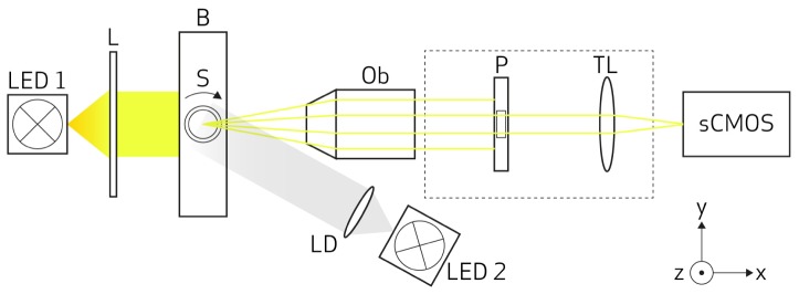
Schematic of the OPT setup: the samples are placed and rotated in the rotation stage (S) which is placed in refractive index matching bath (B). Bright-field illumination is done with a white light (LED1) and telecentric lens (L). Fluorescence illumination is done with a specific wavelength (LED2) collimated with a lens with diffuser (LD). The light detection system consists of an objective lens (Ob), a pinhole (P), a tube lens (TL) and a sCMOS camera.
2.2 Samples used
Three different types of gellan gum (GG) hydrogels and GG combined with black polystyrene particles, and polyethylene terephthalate (PET) fibers were used. The three types of hydrogels differ in the physical crosslinking and different crosslinker quantities: 1. GG with 2% of ionic crosslinker (GG 2% IO), 2. GG with 1.1% of spermine (SPM) ionic crosslinker (GG 1.1% SPM), and 3. GG with 0.6% of spermine (SPM) ionic crosslinker (GG 0.6% SPM). Also, hydrogels phantoms were imaged. GG 0.6% SPM and GG 1.1% SPM was combined with 1% v/v black polystyrene particles (Polysciences, USA) with 10 µm diameter (GG particles), with PET filaments with 16 um of diameter (GG fibers). The gels were prepared inside the FEP tubes. Kurtosis (a measure of the shape of the probability distribution of the image histogram) and entropy (a measure of the randomness of the pixels intensities) were calculated from the projections and reconstructed slices in four samples of each hydrogel type. This quantitative information may possibly be used to characterize different types of GG.
2.3 Pre-reconstruction algorithms
Pre-reconstruction algorithms include correcting illumination heterogeneous and determining the correct center of rotation of the sample. Illumination heterogeneities can be eliminated by subtracting to the projections a flat-field image taken without the sample, as already suggested [7]. However when the specimen is fixed in a capillary, the capillary itself contributes to non-uniform illumination due to the refraction in its walls. To reduce these non-uniformities, the flat-field image should be taken with the empty capillary exactly in the same position as for the images taken with the sample [2]. As this is practically an impossible task, we used a homomorphic filter [12] to normalize the brightness across an image. In this filter, illumination and reflectance components of the image are separated and filtered separately in the frequency domain with a high pass filter [12]. The filter frequency is tested in each image being between 30 and 70 cycles for our samples. Sample vertical movements were quantified with findshift function (DIPimage Toolbox). Only static samples (findshift = 0) were used.
The correct center of rotation is computed by considering the variances between adjacent offset pixels. We defined the rotational center position for each slice, CoRn, as the variance sharpest peak, and it can be found as follows:
| (1) |
where n is the sample slice, N is the pixel number of the line detector and V(c) is the image variance of the reconstructed slice for different assumed offset positions c. The search region between N/4 and 3N/4 was shown large enough to cover the true center of rotation. A decimal search is then performed (dCoRn) by finding the maximum of the fitted curve around the detected CoRn. The image variance can be obtained as:
| (2) |
where and are the pixel value and the average pixel value of the reconstructed slice, respectively.
A deviation smaller than 1% in the alignment between the sample center of rotation and the camera sensor results in a different CoR for each slice of the sample. This must be taken into account in the reconstruction process, in order to obtain high resolution reconstructions. In order to reduce the computing time, the rotational center position is computed for the first and last slice, dCoRi and dCoRf, respectively, and the dCoRn (dCoR for all slices) is computed using the center of rotation function, fCoR, defined by us as follows (n is the number of slice between the initial (i) and the final slice (f)):
| (3) |
Although our samples are almost phase objects, they have microstructures that absorb light. These structures increase with the percentage of crosslinker and can be recovered with FBP algorithms. The reconstruction is computed using the inverse radon transform function iradon from Matlab. The iradon function was modified in order to accept fCoR as the center of rotation, instead of the assumed CoR in the center of the image of the original function. The performance of the algorithm was compared with the traditional variance method. The algorithm is applied to reduced images with 512 x 512 pixels.
To evaluate the algorithm, four samples of the 5 types of samples (GG 2% IO, GG 1.1% SPM, GG 0.6% SPM, GG particles, GG fibers) were used. For each sample, 32 CoRn were calculated using Eq. (1), and the obtained center of rotation were compared with the fCoR values (Eq. (3) using the normalized mean square error (NMSE).
3. Results and discussion
Projection images of GG 1.1% SPM with polystyrene particles before and after filtering can be seen in Fig. 2(a) and 2(b). The filter eliminates the illumination non-uniformities. Projection of GG 2% IO after filtering can be seen in Fig. 2(c). Differences in the microstructure can be seen, GG 2% IO has a denser structure, whereas GG 1.1% SPM is more transparent.
Fig. 2.
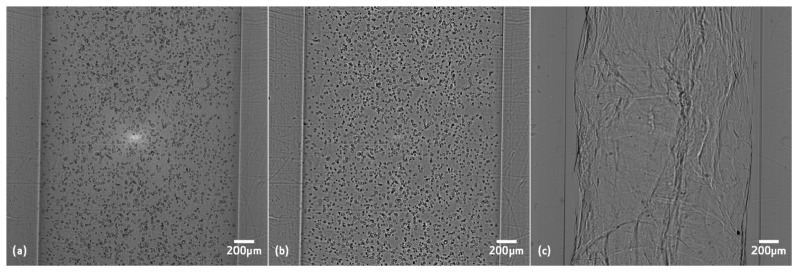
OPT projections of (a) GG with 1.1% of spermine (SPM) ionic crosslinker with polystyrene particles before filtering, (b) same image after homomorphic filtering, and (c) GG with 2% of ionic crosslinker after filtering.
In Fig. 3 it is presented the normalized variance for GG 1.1% SPM [Fig. 3(a)], and GG particles [Fig. 3(b)], as defined in Eq. (2), for different offset values c. The correct CoRi and CoRf are identified as described in Eq. (1), by the black exe and point, respectively. The 32 dCoRn values and the fCoR for two different samples can be seen in Fig. 4. A NMSE higher than 0.91 was obtained for the 5 types of samples evaluated as it can be seen on Table 1.
Fig. 3.
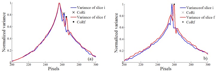
Normalized variance for different offset values for the first and last slice (slice i and slice f, respectively) of (a) GG with 1.1% of spermine (SPM) ionic crosslinker, (b) GG 1.1% ionic was combined with 1% v/v black polystyrene particles. CoRi and CoRf are identified by the black exe and point, respectively.
Fig. 4.
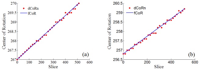
Offset for 32 dCoRn (red dots) and fCoR values (blue line) for (a) GG with 1.1% of spermine (SPM) ionic crosslinker, (b) GG 1.1% ionic was combined with 1% v/v black polystyrene particles.
Table 1. Normalized mean square error (NMSE) of the fit between dCoRn and fCoR values.
| Hydrogel | NMSE ( ± standard deviation) |
|---|---|
| GG 2% IO | 0.9497 ± 0.0039 |
| GG 1.1% SPM | 0.9912 ± 0.0048 |
| GG 0.6% SPM | 0.9935 ± 0.0059 |
| GG particles | 0.9635 ± 0.0506 |
| GG fibers | 0.9181 ± 0.0423 |
Two different reconstructions of the first slice of the GG 1.1% SPM can be seen in Fig. 5. In Fig. 5(a) the dCoR was calculated as the maximum value of the variance, given by the slice i curve peak in Fig. 3(a), as it is done in literature [4, 6]; and in Fig. 5(b) the dCoR is given by the fCoR. It can be seen that the Fig. 5(b) is better reconstructed than Fig. 5(a) because the circle that corresponds to the inner wall is well defined.
Fig. 5.
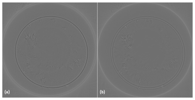
First slice reconstruction of GG with 1.1% of spermine (SPM) ionic crosslinker considering the CoR as (a) the maximum value of variance, and (b) calculated by the center of rotation function fCoR.
The fCoR method presented here has advantages when compared with methods presented in the literature. It is a faster method to calculate the CoR as it calculates the variance of only 2 slices and it gives good results for different hydrogels and phantoms. We have shown that, unlike in earlier studies [3, 4, 6] the correct CoR cannot be found where the variance of the reconstructed images reach their maximum. For the most transparent samples the correct reconstruction does not coincide with the maximum of the variance. However, the best image can be found when the variance reaches a local maximum with a sharp rise and drop. 3D reconstruction of different samples can be seen in Fig. 6. The low intensity voxels were coloured in blue in order to give a clear perception of the microstructures of the hydrogels or to highlight the particles. Table 2 shows kurtosis and entropy mean values, of projections and 3D reconstructions, for each type of hydrogel. For the projections, kurtosis decreases with the increase of microstructures while the opposite happens for entropy. This was expected because high kurtosis is related with a more homogeneous intensities distribution in transparent hydrogels, while high entropy is related with random intensity distribution in high density hydrogels. We examine these parameters in the reconstruction slices in order to see if quantitative information is preserved. The main difference is the kurtosis of GG 2% IO that is not smaller than of the GG 1.1% SPM but we need to take in consideration that the standard deviation (std) of GG 2% IO is very high. This will be studied deeply in a future publication.
Fig. 6.

OPT reconstruction of (a) GG with 2% of ionic crosslinker, (b) GG with 1.1% of spermine (SPM) ionic crosslinker, and (c) GG with 1.1% of spermine (SPM) ionic crosslinker with polystyrene particles.
Table 2. Kurtosis and entropy for the projections and reconstructions of GG with 2% of ionic crosslinker, GG with 1.1% of SPM ionic crosslinker, and GG with 0.6% of SPM ionic crosslinker (mean value ± std).
| Hydrogel | Projections |
Reconstructions |
||
|---|---|---|---|---|
| Kurtosis | Entropy | Kurtosis | Entropy | |
| GG 2% IO | 7.3 ± 1.2 | 5.0 ± 0.33 | 114.7 ± 99.2 | 2.94 ± 0.5 |
| GG 1.1% SPM | 8.7 ± 3.2 | 4.7 ± 0.27 | 43.1 ± 7.9 | 2.52 ± 0.4 |
| GG 0.6% SPM | 35.4 ± 11.8 | 3.7 ± 0.09 | 202.2 ± 65.5 | 1.24 ± 0.3 |
4. Conclusions
In this work we show that we can use OPT to image different types of GG hydrogels.
The fCoR method presented here is a faster method because it avoids the calculation of the center of rotation for all slices. Furthermore the developed specific pre-reconstruction algorithms give an automated method for tomographic images reconstruction suitable for imaging hydrogels and TE constructs based on hydrogels inside FEP tubes.
We have shown that OPT is a suitable tool for imaging hydrogel microstructures and that kurtosis and entropy, could be used to characterize hydrogels according to their optical properties. Further studies include the use of the system to characterize different hydrogels as well as for different evaluation tests used in hydrogels for TE research, as hydrogels stability.
Acknowledgments
The authors thank to Tekes, Finnish Cultural Foundation, CIMO, Jane and Aatos Erkko Foundation and EXTREMA COST Action MP1207 for supporting this work.
References and links
- 1.Sharpe J., Ahlgren U., Perry P., Hill B., Ross A., Hecksher-Sørensen J., Baldock R., Davidson D., “Optical projection tomography as a tool for 3D microscopy and gene expression studies,” Science 296(5567), 541–545 (2002). 10.1126/science.1068206 [DOI] [PubMed] [Google Scholar]
- 2.Birk U. J., Darrell A., Konstantinides N., Sarasa-Renedo A., Ripoll J., “Improved reconstructions and generalized filtered back projection for optical projection tomography,” Appl. Opt. 50(4), 392–398 (2011). 10.1364/AO.50.000392 [DOI] [PubMed] [Google Scholar]
- 3.Appel A. A., Anastasio M. A., Larson J. C., Brey E. M., “Imaging challenges in biomaterials and tissue engineering,” Biomaterials 34(28), 6615–6630 (2013). 10.1016/j.biomaterials.2013.05.033 [DOI] [PMC free article] [PubMed] [Google Scholar]
- 4.Mather M. L., Morgan S. P., Crowe J. A., “Meeting the needs of monitoring in tissue engineering,” Regen. Med. 2(2), 145–160 (2007). 10.2217/17460751.2.2.145 [DOI] [PubMed] [Google Scholar]
- 5.Gibbons M. C., Foley M. A., Cardinal K. O., “Thinking inside the box: keeping tissue-engineered constructs in vitro for use as preclinical models,” Tissue Eng. Part B Rev. 19(1), 14–30 (2013). 10.1089/ten.teb.2012.0305 [DOI] [PubMed] [Google Scholar]
- 6.Haidekker M. A., “Optical transillumination tomography with tolerance against refraction mismatch,” Comput. Methods Programs Biomed. 80(3), 225–235 (2005). 10.1016/j.cmpb.2005.09.002 [DOI] [PubMed] [Google Scholar]
- 7.Walls J. R., Sled J. G., Sharpe J., Henkelman R. M., “Correction of artefacts in optical projection tomography,” Phys. Med. Biol. 50(19), 4645–4665 (2005). 10.1088/0031-9155/50/19/015 [DOI] [PubMed] [Google Scholar]
- 8.Dong D., Zhu S., Qin C., Kumar V., Stein J. V., Oehler S., Savakis C., Tian J., Ripoll J., “Automated recovery of the center of rotation in optical projection tomography in the presence of scattering,” IEEE J. Biomed. Health Inform. 17(1), 198–204 (2013). 10.1109/TITB.2012.2219588 [DOI] [PubMed] [Google Scholar]
- 9.Sharpe J., “Optical projection tomography as a new tool for studying embryo anatomy,” J. Anat. 202(2), 175–181 (2003). 10.1046/j.1469-7580.2003.00155.x [DOI] [PMC free article] [PubMed] [Google Scholar]
- 10.Birk U. J., Rieckher M., Konstantinides N., Darrell A., Sarasa-Renedo A., Meyer H., Tavernarakis N., Ripoll J., “Correction for specimen movement and rotation errors for in-vivo Optical Projection Tomography,” Biomed. Opt. Express 1(1), 87–96 (2010). 10.1364/BOE.1.000087 [DOI] [PMC free article] [PubMed] [Google Scholar]
- 11.Gonzalez R. C., Woods R. E., Digital Image Processing, 3rd ed. (Elsevier, 2007) Chap. 4.9.6 [Google Scholar]


