

Abstract
Brain machine interfaces (BMIs) have the potential to assist in the rehabilitation of millions of patients worldwide. Despite recent advancements in BMI technology for the restoration of lost motor function, a training environment to restore full control of the anatomical segments of an upper limb extremity has not yet been presented. Here, we develop a virtual upper limb prosthesis with 27 independent dimensions, the anatomical dimensions of the human arm and hand, and deploy the virtual prosthesis as an avatar in a virtual reality environment (VRE) that can be controlled in real-time. The prosthesis avatar accepts kinematic control inputs that can be captured from movements of the arm and hand as well as neural control inputs derived from processed neural signals. We characterize the system performance under kinematic control using a commercially available motion capture system. We also present the performance under kinematic control achieved by two non-human primates (Macaca Mulatta) trained to use the prosthetic avatar to perform reaching and grasping tasks. This is the first virtual prosthetic device that is capable of emulating all the anatomical movements of a healthy upper limb in real-time. Since the system accepts both neural and kinematic inputs for a variety of many-dimensional skeletons, we propose it provides a customizable training platform for the acquisition of many-dimensional neural prosthetic control.
Keywords: Brain machine interface, Virtual reality environment
1. Introduction
Millions of people worldwide suffer from intractable medical conditions that result in permanent motor disability (Lebedev et al., 2011). Brain machine interfaces (BMIs) are devices that use recorded neural activity to control external actuators, and have the potential to restore lost function to patients suffering from a variety of motor disorders (Donoghue, 2002; Hatsopoulos and Donoghue, 2009). BMIs that seek to perform arm and hand functions are difficult to design, however, as many dimensions must be under simultaneous control by the patient (Carmena et al., 2003; O'Doherty et al, 2011). Consequently, it is important to develop an environment that can support the training of many-dimensional (many-D) neural prosthetic control.
An exclusive emphasis on robotic devices for many-D BMI control hinders progress for several reasons. Manufacturing many-D prosthetic devices for musculoskeletal rehabilitation is expensive because of the costs associated with fabrication of multiple iterations of these devices (Davoodi and Loeb, 2011). More importantly, current state-of-the-art robotic devices are not yet capable of realtime high dimensional, natural movements that allow users to embody the prosthetic device. Such differences will not allow systematic testing of how these variables may affect neural responses and control of a prosthetic. Virtual devices offer a safe and practical alternative to manufactured robotic devices. Effective control requires many hours of practice in a safe, behaviorally relevant environment which can be achieved through the effective use of virtual reality environments (VREs, Bohil et al, 2011). Major technological developments in recent years have made it possible for VREs to be highly immersive environments, where a multitude of behaviors can be learned and trained (Bohil et al, 2011). Previously, VREs have been shown to be effective rehabilitative tools for retraining motor function following stroke (Jack et al., 2001; Holden et al., 2005; Kuttuva et al., 2005, 2006; Piron et al., 2009; Burdea et al., 2011), treating phantom limb pain conditions in amputees (Murray et al., 2006; Cole et al., 2009; Alphonso et al., 2012) and designing and simulating the use of expensive prosthetic devices prior to fabrication (Soares et al, 2003; Sebelius et al, 2006). This means the development of VRE-based prosthetic training environments offers important new opportunities.
Low-D BMI systems, such as those involving a cursor in Cartesian space (2- or 3-D) and an oriented gripper (4-D to 7-D), have previously been employed in VREs and VREs appear to be a potentially valuable tool (Hauschild et al., 2007; Marathe et al., 2008; Aggarwal et al., 2011; Resnik et al., 2011; Davoodi and Loeb, 2012; Kaliki et al., 2013). However, for a VRE-based BMI training system to be truly effective, it must include a way to make quantitative measures to evaluate user performance in a 3-D environment (Marathe et al., 2008; Resnik et al., 2011), and have real-time capabilities (Schalk et al., 2004; Wilson et al., 2010). Further, for this system to be a viable option for mainstream use, there must be a demonstration of diverse functionality and a software framework that is accessible to as many potential users as possible (Mason and Birch, 2003; Schalk et al., 2004; Brunner et al., 2011).
Despite these advantages, a virtual prosthesis that can emulate all of the dimensions necessary for full control of a human upper limb in real-time is not currently available. Further, upper limb virtual prostheses that currently exist do not have design characteristics that are conducive to a generalized BMI system framework (Bishop et al., 2008), nor do they provide a framework for quantitative assessment of task performance in a 3D environment (Resnik et al., 2011). Here, we discuss a novel method for the development of a virtual, upper limb prosthesis capable of giving the user independent control of 27-D in real-time and then assess the performance metrics of non-human primates using the limb to perform tasks in a 3-D VRE.
2. Methods
2.1. Animal preparation
Two non-human primates (Macaca mulatta) were used for these experiments. All surgical and animal care procedures were approved by the New York University Animal Care and Use Committee and were performed in accordance with National Institutes of Health guidelines for care and use of laboratory animals.
2.2. Motion capture
We used motion capture to allow the virtual prosthesis to be used under kinematic control.
Twenty-four spherical, retro-reflective markers were non-invasively adhered to sites on the upper torso, and multiple bony landmarks on the right upper limb of each subject (Fig. 1A). We used markers whose sizes ranged in diameter from 7 mm (markers on the sternum, shoulders and right elbow; Fig. 1B) to 2 mm (markers on the digits; Fig. 1B). Markers were placed at locations on the upper body to permit the calculation of kinematic information across 27 dimensions, which covers all of the physiological movements of the 19 joints of the upper limb (Table 1). All movements that the animals made inside a rig were captured using 26 infrared (735 nm) and near-infrared (890 nm) cameras capable of motion capture at frame-rates of up to 245 Hz (Osprey Digital Real Time System, Motion Analysis Corp., Santa Rosa, CA). Note that motion capture was needed only when the virtual prosthesis was used under kinematic control. Cameras were placed to permit marker detection by a minimum of three cameras to triangulate a single marker location at any location in a 55 × 45 × 55 cm volume (depth × height × width). System calibration was performed each day prior to data collection sessions, and total localization error on the calibrated system was typically less than 1 mm. In an initial, manual post-processing phase, kinematic data was acquired and markers related to specific upper limb locations were linked to one another such that specific spatial relationships (within a user-defined tolerance) were set to pairs of markers in the set. Through this manual process, specialized upper limb ‘templates’ were generated for each animal, and these templates were trained offline using selected sets of labeled data. In general, templates become more robust to a broader repertoire of actions as more data is used to train them. We found that training a template on five minutes (∼30,000 frames at 100 Hz) of motion capture data was sufficient to accurately track the movements of the upper limb through the task workspace for the specific reaching and grasping behaviors we investigated (power grip and precision grip).
Fig. 1.
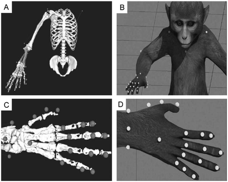
The motion capture system tracks the location of 24 retro-reflective markers that extend from the shoulders to the tips of the fingers. Marker location is determined by proximity to specific bony landmarks (A) that will provide the most accurate information related to joint position, and are then adhered to the skin immediately above these landmarks (B). Successful tracking of this marker-set allows for accurate joint information to be solved across the 20 upper limb joints and 27 specific joint movements (Table 1).
Table 1.
Upper limb joints, their anatomical structure, and the relevant dimensions monitored in this study (kinematic model joint angle constraints for each dimension listed in parentheses).
| Joint(s) | Joint structure | Description of each dimension |
|---|---|---|
| Shoulder | Ball and socket | 1. Flexion (0–180°) |
| 2. Horizontal abduction (−90 to 130°) | ||
| 3. Internal rotation (−120 to 60°) | ||
| Elbow | Hinge | 4. Flexion/extension (−10 to 160°) |
| Radioulnar | Pivot | 5. Pronation/supination (−120 to 120°) |
| Wrist | Condyloid | 6. Flexion/extension (−90 to 90°) |
| 7. Ulnar/radial deviation (−45 to 45°) | ||
| Digit 1 carpometacarpal (CMC) | Saddle | 8. Flexion/extension (−60 to 60°) |
| 9. Abduction/adduction (−60 to 60°) | ||
| Digit 1 metacarpophalangeal (MCP) | Hinge | 10. Flexion/extension (−20 to 120°) |
| Digit 2 metacarpophalangeal (MCP) | Condyloid | 11. Flexion/extension (−75 to 120°) |
| 12. Abduction/adduction (−60 to 60°) | ||
| Digit 3 metacarpophalangeal (MCP) | Condyloid | 13. Flexion/extension (−75 to 120°) |
| 14. Abduction/adduction (−60 to 60°) | ||
| Digit 4 metacarpophalangeal (MCP) | Condyloid | 15. Flexion/extension (−75 to 120°) |
| 16. Abduction/adduction (−60 to 60°) | ||
| Digit 5 metacarpophalangeal (MCP) | Condyloid | 17. Flexion/extension (−75 to 120°) |
| 18. Abduction/adduction (−60 to 60°) | ||
| Digit 1 interphalangeal (IP) | Hinge | 19. Flexion/extension (−20 to 120°) |
| Digit 2 proximal interphalangeal (IP) | Hinge | 20. Flexion/extension (−20 to 120°) |
| Digit 3 proximal interphalangeal (IP) | Hinge | 21. Flexion/extension (−20 to 120°) |
| Digit 4 proximal interphalangeal (IP) | Hinge | 22. Flexion/extension (−20 to 120°) |
| Digit 5 proximal interphalangeal (IP) | Hinge | 23. Flexion/extension (−20 to 120°) |
| Digit 2 distal interphalangeal (IP) | Hinge | 24. Flexion/extension (−20 to 120°) |
| Digit 3 distal interphalangeal (IP) | Hinge | 25. Flexion/extension (−20 to 120°) |
| Digit 4 distal interphalangeal (IP) | Hinge | 26. Flexion/extension (−20 to 120°) |
| Digit 5 distal interphalangeal (IP) | Hinge | 27. Flexion/extension (−20 to 120°) |
2.3. Building a skeletal model
In order to calculate joint angles from marker location, we used a kinematic model to correlate marker position with anatomical movement. We developed a complete upper limb kinematic model for a rhesus macaque in order to drive all of the dimensions in the prosthesis. We first generated an anatomically correct skeletal model of the macaque upper limb. MRI images of the arm, hand and shoulder were collected in a Siemens 3T head-only Allegra scanner (Siemens, Erlangen, Germany) with a volume head coil from Nova Medical (Wilmington, MA) using a 3D Rapid Acquisition with Gradient Echo (RAGE) sequence. The repetition and echo times were 1600 and 4.13 ms respectively, and the flip-angle was 8 degrees with a matrix size of 448 × 144 × 160 at a resolution of 6 mm isotropic. Three runs were collected for the proximal (from the scapula to the proximal portions of the radius and ulna) and the distal (from the distal segment of the humerus to the tips of the fingers) parts of the limb and averaged offline. Scanner gradient non-linearities were corrected using a local implementation of the original tool from the BIRN's Morphometry group (Jovicich et al., 2006). Each set of three MRI scans for each anatomical region was averaged using FSL Tools (Analysis Group, UK). Aligning and averaging multiple scans of the same region yielded an averaged scan with a higher signal-to-noise ratio. The increased signal-to-noise ratio made the process of bone reconstruction easier, principally because the bone-tissue interface is easier to determine. Averaged scans were imported as ‘NIfTI’ (.nii) files into 3D Slicer (Harvard, MA), where three-dimensional renderings of a complete set of upper limb bones (Table 2; 30 bones) were rebuilt from the MRI scans. Once the bones had been rendered, they were imported into SIMM (Musculographics, Inc.), a program that uses kinematic models to calculate joint angles from recorded marker positions.
Table 2.
Bones reconstructed from the MRI, and their associated upper limb joints.
| Reconstructed bone | Associated joint(s) |
|---|---|
| 1. Humerus | Shoulder, elbow |
| 2. Radius | Elbow, radioulnar, wrist |
| 3. Ulna | Elbow, radioulnar, wrist |
| 4. Scaphoid | Wrist |
| 5. Lunate | Wrist |
| 6. Triquetrium | Wrist |
| 7. Pisiform | Wrist |
| 8. Trapezius | Wrist |
| 9. Trapezoid | Wrist |
| 10. Capitate | Wrist |
| 11. Hamate | Wrist |
| 12.1st metacarpal | Wrist, metacarpophalangeal |
| 13. 2nd metacarpal | Wrist, metacarpophalangeal |
| 14. 3rd metacarpal | Wrist, metacarpophalangeal |
| 15. 4th metacarpal | Wrist, metacarpophalangeal |
| 16. 5th metacarpal | Wrist, metacarpophalangeal |
| 17. 1st proximal phalanx | Metacarpophalangeal, interphalangeal |
| 18. 2nd proximal phalanx | Metacarpophalangeal, proximal interphalangeal |
| 19. 3rd proximal phalanx | Metacarpophalangeal, proximal interphalangeal |
| 20. 4th proximal phalanx | Metacarpophalangeal, proximal interphalangeal |
| 21. 5th proximal phalanx | Metacarpophalangeal, proximal interphalangeal |
| 22. 1st distal phalanx | Interphalangeal |
| 23. 2nd middle phalanx | Proximal interphalangeal, distal interphalangeal |
| 24. 3rd middle phalanx | Proximal interphalangeal, distal interphalangeal |
| 25. 4th middle phalanx | Proximal interphalangeal, distal interphalangeal |
| 26. 5th middle phalanx | Proximal interphalangeal, distal interphalangeal |
| 27. 2nd distal phalanx | Distal interphalangeal |
| 28. 3rd distal phalanx | Distal interphalangeal |
| 29. 4th distal phalanx | Distal interphalangeal |
| 30. 5th distal phalanx | Distal interphalangeal |
2.4. Calculating joint angles
To ensure that the virtual prosthesis moves in a realistic manner, the joints are constrained by an anatomically correct kinematic model so that motion of the skeletal model conforms to the anatomical structure of each joint (Table 1). The kinematic model was custom-designed for macaque anatomy, based upon the initial human work of Holzbaur et al. (2005), and allowed the calculation of the motion of all the joints in the upper limb based upon marker position. We generated a kinematic model for each animal in order to adjust for subject-specific anatomy.
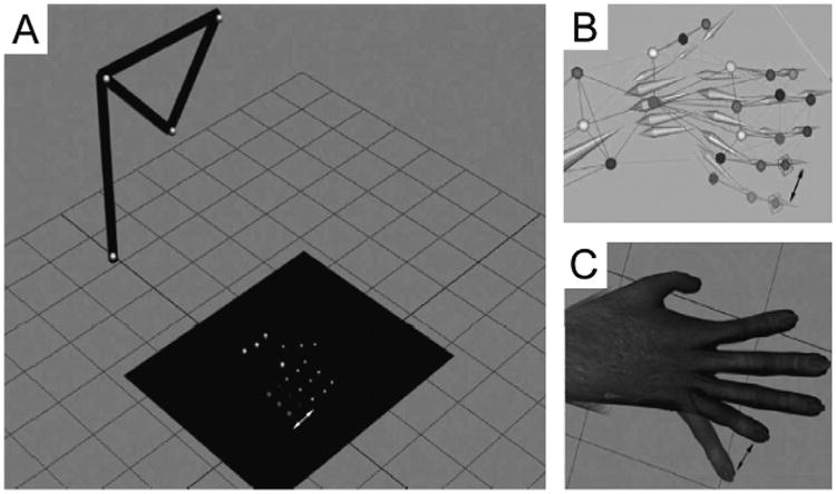
Fig. 2 illustrates the processing pipeline. When motion capture data is input into SIMM (Fig. 2A), marker position is converted to joint angle data using the SIMM kinematic model (Fig. 2B). A ‘segmental model’ is also generated, which generates a skeletal pose for each frame of data based on marker location (Fig. 2C). We also interface the kinematic model with Cortex directly in order to generate a segmental model in real-time, as marker position is being detected by the motion capture system. During online solving sessions, segment position is streamed out of Cortex into the VRE to drive the upper limb avatar (see below).
Fig. 2.
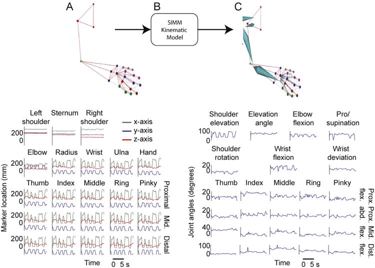
(A) An upper limb marker-set is identified in real-time, and each marker is denoted by a different color, note the linkages (gray lines) between pairs of markers. These links dictate the template logical constraints for spatial relationships between linked markers (top). The x-, y- and z-positions of all markers, measured in millimeters from a pre-calibrated origin (bottom). (B) Marker location data is input into the SIMM kinematic model. (C) The kinematic model outputs a 36-D, HTR segmental model that follows the movements of the upper limb markerset in real-time (top), and joint angles for the 27 upper limb joint movements are output.
2.5. Animating the virtual arm
A Macaca mulatta mesh was designed in 3Ds Max (Autodesk, San Francisco, CA). Avatar meshes that are compatible with 3Ds Max are covered in thousands of vertices that can be programmed to move in synergy with our segmental model in order to give the appearance of natural movement (Fig. 3A). We export a copy of the segmental model to 3Ds Max as a hierarchical translation-rotation (HTR) file. The HTR format ensures that not only is information about segment position maintained in the transfer, but so are the parent–child hierarchies present between individual segments (as specified by the kinematic model) that only allow the arm to adopt anatomically plausible poses. Each segment is aligned to its corresponding anatomical region on the avatar, and the vertices on the mesh are bound to their appropriate segments, such that movements of each segment results in natural movements of the mesh that has been bound to it (Fig. 3B). This same process can be used to create avatars for the objects that the animals are trained to interact with in the VRE. Once the avatar is completed, it is exported from 3Ds Max to Vizard (Worldviz, CA), a commercially available virtual reality engine that can be used to build and render customized virtual environments.
Fig. 3.
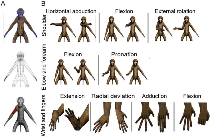
(A) The macaque avatar mesh that was selected to represent rhesus macaque appearance in the VRE (top). The blue dots represent vertices (5248 in total) that segments can be bound to in order to move portions of mesh during segmental motion. A wireframe visualization (middle) of the same mesh, shows how the HTR segmental model is fit to the appropriate anatomical regions. Once correctly placed, each segment is then rigged to the mesh (bottom) such that movement of the segments results in natural movement of the avatar skin. (B) Visualization of the avatar moving through the range of anatomical movements possible at the shoulder (top), elbow and forearm (middle), and wrist and finger (bottom) joints.
2.6. Control of the avatar in real-time
The upper limb avatar renderer in the Vizard VRE receives “movement instructions” via the Motion Analysis “Software Developer Kit 2” (SDK2) interface, and a customized SDK2 client for Vizard. The coordinates of the segmental data information generated in Cortex are sent to Vizard via a User Datagram Protocol (UDP) socket connection. During behavioral experiments, the segment information streamed out of Cortex is used to drive a 36-D macaque avatar and, if necessary, a 6-D (3 orientational dimensions + 3 translational dimensions) wand avatar in real-time. Although a 27-D segmental model can fully characterize all of the anatomical movements of the upper limb, a further 9 dimensions are required to place the entire avatar, trunk and upper limb extremity, in a location and orientation in the VRE. Fig. 4 presents a system diagram of the components required to generate the real-time, interactive VRE.
Fig. 4.
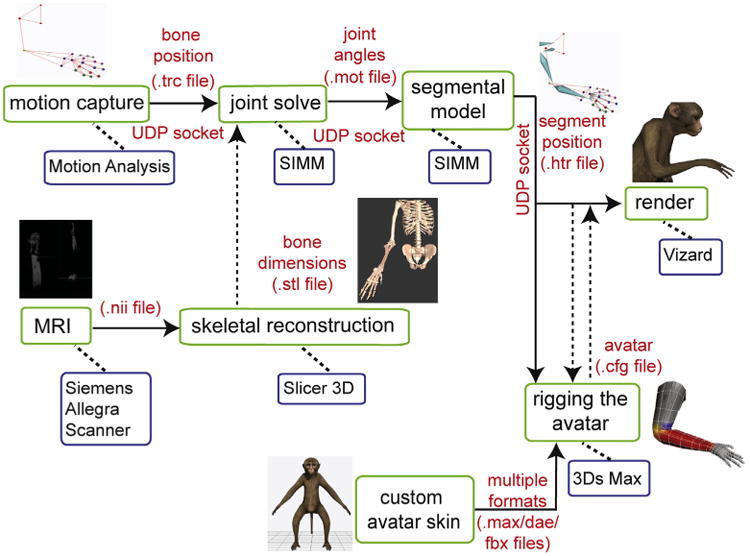
System diagram showing the software and hardware pipelines necessary to produce avatar rendering and motion from kinematic data input in real-time. Solid arrows denote data that is being streamed in real-time, while dashed arrows denote files that are statically loaded into the appropriate programs. Our system is designed such that, offline, the avatar can be rendered and driven by data saved in any of the motion capture data file formats listed in the parts of the system diagram that are connected by solid arrows.
2.7. Designing the VRE workspace
We constructed an immersive, 3-D VRE by erecting a barrier of opaque, light absorbing curtains around the heads of the animals, to completely obscure their view of the regular workspace inside the rig. We mounted a mirror directly in front of the animals, tilted at a 45-degree angle, and projected stereoscopic images of the VRE downward onto the mirror using a 3-D monitor (Dimension Technologies Inc.). This provided the animals with a view of the 3-D VRE when looking into the mirror (Fig. 5A). To ensure that the stereoscopic images were being projected in a trajectory such that the target eye was reached for each image, we calculated the sitting distance from the mirror for each animal based upon inter-ocular distance (Fig. 5B). We first calibrated the correct distance from the mirror by using a human subject, and then adjusted the calculation for each animal using standard trigonometric transforms.
Fig. 5.
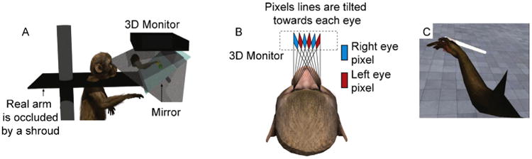
(A) A 3-D monitor projects a stereoscopic image onto a tilted, mirrored surface. From this vantage point, the animal can see the virtual avatar, as well as any task-related objects being rendered in the VRE, but the animal's view of its own limb is completely obscured. (B) A schematic of the display strategy for presenting the animal with 3-D information: based on inter-ocular distance, each animal is placed a specific distance from the mirrored surface so that the stereoscopic images reach their respective eyes accurately. (C) A screenshot of the animal's visual perspective in the VRE as a virtual center-out task is being performed.
2.8. Behavioral tasks
We trained animals to perform virtual versions of a 3-D ‘center-out’ task, and a reaching and grasping task in the VRE. The virtual center-out task required each animal to reach to one of 17 targets in the virtual environment from a central starting position. Each animal started a new trial by moving the proximal phalanx of the avatar's middle finger to a central starting position (cued by presentation of a green sphere), and holding their limb within that location for a minimum of 500 ms. A green, spherical target was then presented at one of 17 locations at random along a 44 × 44 × 10 cm (width × height × depth) rectangular prism in the VRE, immediately following which the animal was required to move the avatar to the cued location and then hold its position for 500 ms. A trial was considered successful if a marker on the hand of the prosthesis was held in a space within 7 cm of the target (Fig. 5C). We measured time to target acquisition from the time of movement onset, to assess task performance and whether the animals were using 3-D information about target location from the VRE. The animal performed blocks of trials of the virtual center-out task with the monitor randomly switching between its 3-D and 2-D mode. Switching monitor modes made accurate task performance more difficult during 2-D trials, by depriving the animal of 3-D information about target location. We hypothesized that if the animal is using 3-D information to locate the targets, task performance should decay during 2-D trials compared with 3-D trials.
2.9. System latency calculation
We define system latency as the period of time between motion capture of a movement in the real world, and actuation of that movement through the avatar in the VRE. To test system latency in a stable environment, we constructed an artificial arm, made of motion capture markers strategically placed to resemble a complete upper limb marker-set. In place of the three markers that are usually on the phalanges of digit 5, we attached six light emitting diodes (LEDs; Fig. 6A), arranged in two rows of three, side-by-side on a circuit-board, such that activation of the switch alternately lights one set of 3 LEDs, simulating finger motion between two distinct positions (Fig. 6B). A photo-diode was attached to the display monitor, on the artificial finger's end position, such that it would discharge a signal pulse every time the avatar's finger moves to the end position on the monitor (Fig. 6C). Signals from the switch responsible for shifting “finger position” on the circuit board, and the photo-diode were recorded with a sampling rate of 30 kHz. System latency was calculated by finding the temporal delay between the switch and photodiode signals across multiple trials. Latency calculations were performed whilst manipulating multiple display parameters in order to assess their contributions to system latency. The parameters that we manipulated during our measurements were: the refresh rate of the display monitor, the frame rate of the motion capture cameras, and synchronization between the CPU and GPU (glFinish on/off).
Fig. 6.
Function of the “artificial arm” apparatus that allowed us to test total system latency. (A) Two sets of LEDs are alternately lit, representing two distinct Digit 5 positions. (B) This “marker movement” is detected by the motion capture system, and the segmental model moves accordingly. (C) The change in segment position causes a reciprocal change in avatar finger location.
3. Results
3.1. Kinematic control – system latency
Altering different aspects of our rendering system proved effective in decreasing system latency. Modulation of monitor refresh rate had a clear effect on system latency – as refresh rate was increased, a significant decrease in latency was seen ((p < 0.001 rank-sum test; Fig. 7A). Similarly, when camera frame-rate was modulated from 50 Hz to 245 Hz in 25 Hz increments, a significant effect was seen between latencies measured at low and high frame-rates (p < 0.001 rank-sum test; Fig. 7B). We also considered how the rendering computer prioritizes the incoming data. Vizard uses openGL (http://www.opengl.org/) as the software interface to the rendering machine's graphic card. OpenGL has a data processing command known as ‘glFinish’, which sets the system to prioritize the rendering of frames by blocking all other operations until OpenGL finishes rendering what is in its buffer (Shreiner and Group, 2009). We ran latency calculations with glFinish toggled on (dashed lines; Fig. 7A and B), and off (solid lines; Fig. 7A and B). Using glFinish did not have consistent effects. The main benefit of using glFinish was that rendering latencies were more predictable across multiple conditions – since glFinish prioritizes rendering, latencies are less likely to spike unexpectedly due to the CPU prioritizing other, external processes over rendering (Fig. 7A and B). Using a camera frame-rate of 245 Hz, glFinish, and a monitor refresh rate of 120 Hz we achieved the lowest rendering latency for the 36-D avatar: 32.51 ± 4.5 ms. We monitored changes in system performance when scenes of varying complexity were being rendered in the VRE. Given the results of our previous measures, these data were collected with glFinish on, a camera frame rate of 245 Hz and a monitor refresh rate of 120 Hz to facilitate the lowest possible latencies for these measures. Total system latency ranged from 26.82 ± 3.02 (1-D) to 35.80 ± 3.69 (48-D) as virtual scene complexity was manipulated (Fig. 7C).
Fig. 7.

(A) Plots showing how total system latency is affected by manipulating camera frame-rate at specific monitor refresh-rates. (B) Plots showing how total system latency is affected by manipulating monitor refresh-rate at specific camera frame-rates. Measurements were made with glFinish on and off for the purpose of comparison. (C) Plot showing SDK and total system latencies as avatar complexity is manipulated.
3.2. Kinematic control – task performance
Performance of the virtual center-out task provided a way for us to ascertain with confidence whether or not the animal successfully utilizes the 3-D information being presented in the VRE. As the animal performed the task, the monitor projecting the VRE was toggled between its 2-D and 3-D settings in a randomized manner between blocks of trials. A comparison of time to target acquisition and accuracy between 2-D and 3-D center-out trials was analyzed using data collected during 6 behavioral sessions, consisting of a total of 4932 reaching trials (2918 3-D and 2014 2-D trials). Time to target acquisition was significantly shorter by 201 ± 43 ms during 3-D trials than 2-D trials (Fig. 8A; p < 0.05, rank-sum test). The percentage of successfully completed trials per session was increased by 4.6 ± 0.9% during 3-D trials, which was also significant (Fig. 8B; p < 0.05, rank-sum test). Finally, during successful task performance, the animal also showed significantly less variance in hand trajectory in the depth-dependent axis during target acquisition during 3-D (12.9 ± 0.1 mm) compared with 2-D trials (16.4 ± 0.2 mm; Fig. 8C; p < 0.001, rank-sum test). Therefore, the animal was capable of using 3-D information presented in the VRE to improve center-out task performance.
Fig. 8.

Differences in task performance between 2-D and 3-D trials. (A) Time to target acquisition from the ‘Go’ cue. (B) Percentage of correct trials per behavioral session. (C) Variability of hand trajectory to the target between the ‘Go’ cue and target acquisition.
3.3. Custom-designed plugin allows avatar control with multiple inputs
In order to provide neural control of the virtual prosthesis, we developed a server to emulate the role of the Cortex software in the system (presented in Fig. 4). The HTR model generator is integrated with the SIMM software in order to allow us to input data of any form, and transform it to movement commands that can be used to control our avatar. To the Vizard software, our HTR model generator appears to send data that is identical to that which it receives from the real Cortex server, in so much as it appears to provide both an HTR skeleton for animation and free angles/parameters of the kinematic model in real time via a network UDP stream. In neural control experiments, this feature allows kinematic control software (Cortex) to be removed from the rendering pipeline. The virtual prosthesis can then be controlled using the output of a decoder that calculates all 27 joint angles of the skeletal model from neural activity in real-time (Fig. 9).
Fig. 9.
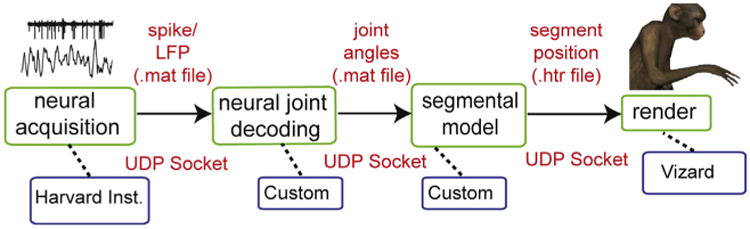
System diagram showing software and hardware pipeline that enables avatar generation and control based on processed neural signals.
4. Discussion
The present study describes the development of a many-D, anthropomorphic virtual prosthetic device capable of allowing independent control of 27 dimensions in a real-time virtual environment. To our knowledge, this is the first report of a virtual prosthesis that is capable of allowing a user to exert independent control of all of the anatomical movements of a real upper limb in real-time.
4.1. Animal performance in the virtual world
In order for our VRE to be an effective training environment for future non-human primate experiments, it was essential that we demonstrate that our animals are capable of correctly interpreting information presented in the VRE, and responding appropriately to virtual cues. Animal performance in the virtual center-out task confirmed that the animals are capable of perceiving the full 3-D effect of the VRE. Further, training of the 3-D center-out task was performed exclusively in the VRE, demonstrating that non-human primates can be successfully trained to perform target-reaching tasks in an immersive VRE.
4.2. Definition of ‘real-time’ control
Real-time control across many degrees of freedom needs to be quantified to ensure that the latencies associated with device control do not lead to aberrant movement patterns due to temporal delays between input signals and visual feedback of actualization. When the virtual prosthesis was driven by kinematic data (as acquired from the motion capture system), we measured total latency from marker position acquisition to visualization of the VRE on the mirror as 32.51 ± 4.5 ms. Many psychophysical experiments have been performed to assess the effect of a visual feedback delay on pointing (target reaching) and grasping strategies (Miall et al., 1985,1986; Vercher and Gauthier, 1992; Foulkes and Miall, 2000; Miall and Jackson, 2006; Sarlegna et al., 2010). These studies suggest that visual feedback delays do not significantly impede task performance unless they are longer than 100 ms (Miall et al., 1985, 1986; Foulkes and Miall, 2000). Thus, the current measured system latency falls well below what is necessary to give the impression of real-time interaction with the VRE. The current study also gives an indication of how lesser system setups that can produce sub-100 ms system latencies using VRE development. Furthermore, as more powerful technologies become available for driving the kinematic and rendering processes, we can expect lower calculation and rendering times for more complex VREs.
4.3. Versatility of the device framework
BMI devices designed to be applied to multiple mainstream applications should adhere to specific guidelines that have been previously determined (Mason and Birch, 2003; Bishop et al., 2008). For the current VRE, we took care to adhere to these guidelines so that the system can receive and interpret multiple inputs from a range of sources: neural, kinematic, or otherwise to drive the prosthesis in real-time at variable dimensions in the VRE (Fig. 9).
4.4. Expanding dimensionality of the prosthesis and enhancing the VRE
The virtual prosthesis detailed in this study fully replicates the anatomical capabilities of a healthy upper limb. However, expanding the scope and dimensionality of the prosthesis may be instrumental in assisting those suffering from more severe impairments, enhancing embodiment of the prosthesis in an immersive VRE, or improving the decoding quality of BMI algorithms. Previous work has suggested that a subject's embodiment of a prosthetic device may result in improved BMI performance, and taking steps to improve the realism and detail of the VRE is an important step in encouraging embodiment of a virtual prosthesis (Riva et al., 2011). In the current study, we used one of multiple head-fixed approaches to create the impression of a 3-D VRE for our subjects. Use of an appropriate head-mounted device would serve to greatly enhance the realism of the VRE, and potentially further encourage embodiment of the prosthesis, but would also require tracking of head and cervical vertebra positions, further increasing the dimensionality of the kinematic model. Effective neural decoding algorithms are essential to reliable control of a high-dimensional prosthetic device, and it remains controversial whether these algorithms are more effective if they are used to drive kinetic features of the upper limb (Cherian et al., 2011; Ouanezar et al., 2011; Ethier et al., 2012). Addition of a complete kinetic model to the existing kinematic framework would provide valuable information as to whether an optimal decoding solution involves the use of a kinetic, kinematic or combined model.
4.5. Alternate applications of this technology
The successful development of the virtual prosthesis described in this study represents a highly versatile tool that can be applied to multiple rehabilitative situations. Observation of a low-quality virtual limb performing basic stretches and navigating/performing functional tasks in simple VREs has been shown to be beneficial in treating chronic pain conditions (Murray et al., 2006; Cole et al., 2009; Alphonso et al., 2012), and improving motor function in chronic stroke patients (Jack et al., 2001; Burdea et al., 2010). Previous work has suggested that the application of higher resolution, better quality VREs, and more realistic virtual limbs to these rehabilitation paradigms would greatly improve the efficacy of these approaches (Bohil et al., 2011).
Highlights.
A virtual upper limb prosthesis with 27 anatomically defined dimensions is deployed as an avatar in virtual reality.
The prosthesis avatar accepts kinematic control inputs and neural control inputs.
Performance under kinematic control is achieved by two non-human primates using the prosthesis avatar to perform reaching and grasping tasks.
This is the first virtual prosthetic device that is capable of emulating all the anatomical movements of a healthy upper limb in real-time.
This is customizable training platform for the acquisition of many-dimensional neural prosthetic control.
Acknowledgments
The authors would like to acknowledge the work of Dustin Hatfield and Phil Hagerman for help with motion capture, Andrew Schwartz for sharing the macaque mesh, and Peter Loan for help with development of the rhesus macaque kinematic model. This work was sponsored by the Defense Advanced Research Projects Agency (DARPA) MTO under the auspices of Dr. Jack Judy through the Space and Naval Warfare Systems Center, Pacific Grant/Contract No. N66001-11-1-4205. BP was supported by a Career Award in the Biomedical Sciences from the Burroughs-Wellcome Fund, a Watson Program Investigator Award from NYSTAR, a Sloan Research Fellowship and a McKnight Scholar Award.
References
- Aggarwal V, Kerr M, Davidson AG, Davoodi R, Loeb GE, Schieber MH, et al. Cortical control of reach and grasp kinematics in a virtual environment using musculoskeletal modeling software. Conf Proc IEEE Eng Med Biol Soc. 2011 Apr; http://dx.doi.org/10.1109/NER.2011.5910568.
- Alphonso AL, Monson BT, Zeher MJ, Armiger RS, Weeks SR, Burck JM, et al. Use of a virtual integrated environment in prosthetic limb development and phantom limb pain. Stud Health Technol Inform. 2012;181:305–9. [PubMed] [Google Scholar]
- Bishop W, Armiger R, Burck J, Bridges M, Hauschild M, Englehart K, et al. A realtime virtual integration environment for the design and development of neural prosthetic systems. Conf Proc IEEE Eng Med Biol Soc. 2008:615–9. doi: 10.1109/IEMBS.2008.4649228. [DOI] [PubMed] [Google Scholar]
- Bohil CJ, Alicea B, Biocca FA. Virtual reality in neuroscience research and therapy. Nat Rev Neurosci. 2011;12:752–62. doi: 10.1038/nrn3122. [DOI] [PubMed] [Google Scholar]
- Brunner P, Bianchi L, Guger C, Cincotti F, Schalk G. Current trends in hardware and software for brain-computer interfaces (BCIs) J Neural Eng. 2011;8:025001. doi: 10.1088/1741-2560/8/2/025001. [DOI] [PubMed] [Google Scholar]
- Burdea G, Cioi D, Martin J, Rabin B, Kale A, Disanto P. Motor retraining in virtual reality: a feasibility study for upper-extremity rehabilitation in individuals with chronic stroke. Phys Ther. 2011;25 [Google Scholar]
- Burdea GC, Cioi D, Martin J, Fensterheim D, Holenski M. The Rutgers Arm II: rehabilitation system – a feasibility study. IEEE Trans Neural Syst Rehabil Eng. 2010;18:505–14. doi: 10.1109/TNSRE.2010.2052128. [DOI] [PubMed] [Google Scholar]
- Carmena JM, Lebedev MA, Crist RE, O'Doherty JE, Santucci DM, Dimitrov DF, et al. Learning to control a brain-machine interface for reaching and grasping by primates. PLoS Biol. 2003;1:E42. doi: 10.1371/journal.pbio.0000042. [DOI] [PMC free article] [PubMed] [Google Scholar]
- Cherian A, Krucoff MO, Miller LE. Motor cortical prediction of EMG: evidence that a kinetic brain–machine interface may be robust across altered movement dynamics. J Neurophysiol. 2011;106:564–75. doi: 10.1152/jn.00553.2010. [DOI] [PMC free article] [PubMed] [Google Scholar]
- Cole J, Crowle S, Austwick G, Slater DH. Exploratory findings with virtual reality for phantom limb pain; from stump motion to agency and analgesia. Disabil Rehabil. 2009;31:846–54. doi: 10.1080/09638280802355197. [DOI] [PubMed] [Google Scholar]
- Davoodi R, Loeb G. Real-time animation software for customized training to use motor prosthetic systems. IEEE Trans Neural Syst Rehabil Eng. 2011 Dec; doi: 10.1109/TNSRE.2011.2178864. http://dx.doi.org/10.1109/TNSRE.2011.2178864. [DOI] [PubMed]
- Davoodi R, Loeb GE. Real-time animation software for customized training to use motor prosthetic systems. IEEE Trans Neural Syst Rehabil Eng. 2012;20:134–42. doi: 10.1109/TNSRE.2011.2178864. [DOI] [PubMed] [Google Scholar]
- Donoghue JP. Connecting cortex to machines: recent advances in brain interfaces. Nat Neurosci. 2002;5(Suppl):1085–8. doi: 10.1038/nn947. [DOI] [PubMed] [Google Scholar]
- Ethier C, Oby ER, Bauman MJ, Miller LE. Restoration of grasp following paralysis through brain-controlled stimulation of muscles. Nature. 2012;485:368–71. doi: 10.1038/nature10987. [DOI] [PMC free article] [PubMed] [Google Scholar]
- Foulkes AJ, Miall RC. Adaptation to visual feedback delays in a human manual tracking task. Exp Brain Res. 2000;131:101–10. doi: 10.1007/s002219900286. [DOI] [PubMed] [Google Scholar]
- Hatsopoulos NG, Donoghue JP. The science of neural interface systems. Annu Rev Neurosci. 2009;32:249–66. doi: 10.1146/annurev.neuro.051508.135241. [DOI] [PMC free article] [PubMed] [Google Scholar]
- Hauschild M, Davoodi R, Loeb GE. A virtual reality environment for designing and fitting neural prosthetic limbs. IEEE Trans Neural Syst Rehabil Eng. 2007;15(9–15) doi: 10.1109/TNSRE.2007.891369. [DOI] [PubMed] [Google Scholar]
- Holden MK, Dyar TA, Schwamm L, Bizzi E. Virtual-environment-based telerehabilitation in patients with stroke. Presence Teleoperators Virtual Environ. 2005;14:214–33. [Google Scholar]
- Holzbaur KRS, Murray WM, Delp SL. A model of the upper extremity for simulating musculoskeletal surgery and analyzing neuromuscular control. Ann Biomed Eng. 2005;33:829–40. doi: 10.1007/s10439-005-3320-7. [DOI] [PubMed] [Google Scholar]
- Jack D, Boian R, Merians AS, Tremaine M, Burdea GC, Adamovich SV, et al. Virtual reality-enhanced stroke rehabilitation. IEEE Trans Neural Syst Rehabil Eng. 2001;9:308–18. doi: 10.1109/7333.948460. [DOI] [PubMed] [Google Scholar]
- Jovicich J, Czanner S, Greve D, Haley E, van der Kouwe A, Gollub R, et al. Reliability in multi-site structural MRI studies: effects of gradient non-linearity correction on phantom and human data. Neuroimage. 2006;30:436–43. doi: 10.1016/j.neuroimage.2005.09.046. [DOI] [PubMed] [Google Scholar]
- Kaliki RR, Davoodi R, Loeb GE. Evaluation of a noninvasive command scheme for upper-limb prostheses in a virtual reality reach and grasp task. IEEE Trans Biomed Eng. 2013;60:792–802. doi: 10.1109/TBME.2012.2185494. [DOI] [PubMed] [Google Scholar]
- Kuttuva M, Boian R, Merians A, Burdea G, Bouzit M, Lewis J, et al. The Rutgers Arm: an upper-extremity rehabilitation system in virtual reality. Rehabilitation (Stuttg) 2005:1–8. doi: 10.1089/cpb.2006.9.148. [DOI] [PubMed] [Google Scholar]
- Kuttuva M, Boian R, Merians A, Burdea G, Bouzit M, Lewis J, et al. The Rutgers Arm: a rehabilitation system in virtual reality: a pilot study. Cyberpsychol Behav. 2006;9:148–51. doi: 10.1089/cpb.2006.9.148. [DOI] [PubMed] [Google Scholar]
- Lebedev MA, Tate AJ, Hanson TL, Li Z, O'Doherty JE, Winans JA, et al. Future developments in brain-machine interface research. Clinics. 2011;66(Suppl. 1):25–32. doi: 10.1590/S1807-59322011001300004. [DOI] [PMC free article] [PubMed] [Google Scholar]
- Marathe AR, Carey HL, Taylor DM. Virtual reality hardware and graphic display options for brain-machine interfaces. J Neurosci Methods. 2008;167:2–14. doi: 10.1016/j.jneumeth.2007.09.025. [DOI] [PMC free article] [PubMed] [Google Scholar]
- Mason SG, Birch GE. A general framework for brain-computer interface design. IEEE Trans Neural Syst Rehabil Eng. 2003;11:70–85. doi: 10.1109/TNSRE.2003.810426. [DOI] [PubMed] [Google Scholar]
- Miall RC, Jackson JK. Adaptation to visual feedback delays in manual tracking: evidence against the Smith predictor model of human visually guided action. Exp Brain Res. 2006;172:77–84. doi: 10.1007/s00221-005-0306-5. [DOI] [PubMed] [Google Scholar]
- Miall RC, Weir DJ, Stein JF. Visuomotor tracking with delayed visual feedback. Neuroscience. 1985;16:511–20. doi: 10.1016/0306-4522(85)90189-7. [DOI] [PubMed] [Google Scholar]
- Miall RC, Weir DJ, Stein JF. Manual tracking of visual targets by trained monkeys. Behav Brain Res. 1986;20:185–201. doi: 10.1016/0166-4328(86)90003-3. [DOI] [PubMed] [Google Scholar]
- Murray CD, Patchick E, Pettifer S, Caillette F, Howard T. Immersive virtual reality as a rehabilitative technology for phantom limb experience: a protocol. Cyberpsychol Behav. 2006;9:167–70. doi: 10.1089/cpb.2006.9.167. [DOI] [PubMed] [Google Scholar]
- O'Doherty JE, Lebedev MA, Ifft PJ, Zhuang KZ, Shokur S, Bleuler H, et al. Active tactile exploration using a brain-machine-brain interface. Nature. 2011;(479):228–31. doi: 10.1038/nature10489. [DOI] [PMC free article] [PubMed] [Google Scholar]
- Ouanezar S, Eskiizmirliler S, Maier MA. Asynchronous decoding of finger position and of EMG during precision grip using CM cell activity: application to robot control. J Integr Neurosci. 2011;10:489–511. doi: 10.1142/S0219635211002853. [DOI] [PubMed] [Google Scholar]
- Piron L, Turolla A, Agostini M, Zucconi C, Cortese F, Zampolini M, et al. Exercises for paretic upper limb after stroke: a combined virtual-reality and telemedicine approach. J Rehabil Med. 2009;41:1016–102. doi: 10.2340/16501977-0459. [DOI] [PubMed] [Google Scholar]
- Resnik L, Etter K, Klinger SL, Kambe C. Using virtual reality environment to facilitate training with advanced upper-limb prosthesis. J Rehabil Res Dev. 2011;48:707–18. doi: 10.1682/jrrd.2010.07.0127. [DOI] [PubMed] [Google Scholar]
- Riva G, Waterworth JA, Waterworth EL, Mantovani F. From intention to action: the role of presence. New Ideas Psychol. 2011;29:24–37. [Google Scholar]
- Sarlegna FR, Baud-Bovy G, Danion F. Delayed visual feedback affects both manual tracking and grip force control when transporting a handheld object. J Neurophysiol. 2010;104:641–53. doi: 10.1152/jn.00174.2010. [DOI] [PubMed] [Google Scholar]
- Schalk G, McFarland DJ, Hinterberger T, Birbaumer N, Wolpaw JR. BCI2000: a general-purpose brain-computer interface (BCI) system. IEEE Trans Biomed Eng. 2004;51:1034–43. doi: 10.1109/TBME.2004.827072. [DOI] [PubMed] [Google Scholar]
- Sebelius F, Eriksson L, Balkenius C, Laurell T. Myoelectric control of a computer animated hand: a new concept based on the combined use of a tree-structured artificial neural network and a data glove. J Med Eng Technol. 2006:2–10. 30. doi: 10.1080/03091900512331332546. [DOI] [PubMed] [Google Scholar]
- Shreiner D Group BTKOAW. OpenGL programming guide: the official guide to learning OpenGL, Versions 3.0 and 3.1. Pearson Education; 2009. Google eBook. [Google Scholar]
- Soares A, Andrade A, Lamounier E, Carrijo R. The development of a virtual myoelectric prosthesis controlled by an EMG pattern recognition system based on neural networks. J Intell Inf Syst. 2003;21:127–41. [Google Scholar]
- Vercher JL, Gauthier GM. Oculo-manual coordination control: ocular and manual tracking of visual targets with delayed visual feedback of the hand motion. Exp Brain Res. 1992;90:599–609. doi: 10.1007/BF00230944. [DOI] [PubMed] [Google Scholar]
- Wilson JA, Mellinger J, Schalk G, Williams J. A procedure for measuring latencies in brain–computer interfaces. IEEE Trans Biomed Eng. 2010;57:1785–97. doi: 10.1109/TBME.2010.2047259. [DOI] [PMC free article] [PubMed] [Google Scholar]