Abstract.
Optical microangiography (OMAG) has been extensively utilized to study three-dimensional tissue vasculature in vivo. However, with the limited image resolution () of the commonly used systems, some concerns were raised: (1) whether OMAG is capable of providing the imaging of capillary vessels that are of an average diameter of ; (2) if yes, whether OMAG can provide meaningful quantification of vascular density within the scanned tissue volume. Multiphoton microscopy (MPM) is capable of depth-resolved high-resolution () imaging of biological tissue structures. With externally labeled plasma, the vascular network including single capillaries can be well visualized. We compare the vascular images of in vivo mouse brain acquired by both OMAG and MPM systems. We found that within the penetration depth range of the MPM system, OMAG is able to accurately visualize blood vessels including capillaries. Although the resolution of OMAG may not be able to 100% resolve two closely packed tiny capillaries in tissue, it is still capable of visualizing most of the capillaries because there are interstitial tissue spaces between them. We believe our validation results reinforce the application of OMAG in microvasculature-related studies.
Keywords: multiphoton microscopy, optical microangiography, microvascular imaging
Vasculature is an integral and essential part of human body and plays a significant role in maintaining the healthy state of living tissue. Blood vessels are also heavily involved in a variety of health-related conditions. For example, angiogenesis is necessary to sustain the newly formed granulation tissue in the wound healing process.1,2 Moreover, cells require oxygen and nutrients for their survival and, therefore, tumors cannot grow or metastasize without the support of a functional vasculature.3,4
The vascular network has been previously studied mainly using traditional histological analysis,5 which is highly invasive and may not well represent the morphology under living environments. Some noninvasive techniques, such as laser Doppler imaging (LDI),6 laser Doppler flowmetry (LDF),7 ultrasound imaging,8 and MRI9 have been used to study changes in blood flow in many physiological states. However, the limited spatial and temporal resolution prevents these techniques from imaging small capillary vessels. Moreover, high-resolution x-ray computed tomography (microCT) systems in combination with various contrast agents (i.e., MICROFIL) have been used to image rodent vasculature,10 and to study the therapeutic effect in diseased blood vasculature. The capability of performing in vivo deep animal vasculature imaging is also advantageous compared to most of the optical imaging techniques. However, the limited image resolution leads to difficulty in imaging capillary vessels.
Optical coherence tomography (OCT), which is a noninvasive imaging technique, can provide cross-sectional morphological visualization of tissue microstructures in vivo with a micron-level image resolution.11 Optical microangiography (OMAG), as one of the most significant extensions of traditional OCT technique, is able to image the volumetric vasculature and blood perfusion map down to capillary level in vivo.12,13 OMAG has been extensively utilized to study three-dimensional (3-D) tissue vasculature in vivo,14–20 for example, cerebrovascular blood perfusion in mice.14–16 Many researchers have also employed OMAG for quantitative analysis of blood flow in vessels down to the capillary level.17–20 In clinical ophthalmology, the acquired OMAG vascular images are usually compared and validated with the gold standard fluorescence angiography (FA). However, FA has very limited imaging resolution and lacks the capability of optical sectioning. Therefore, FA is not able to provide the depth information of the vascular network. Multiphoton microscopy (MPM), which is based on a nonlinear excitation effect, can achieve submicron level image resolution with inherent optical sectioning capability. With externally labeled plasma or red blood cells, a vascular network including single capillaries can be well visualized and resolved. In the present study, we compare the vascular images of in vivo mouse brain acquired from both OMAG and MPM systems. We found that within the penetration depth range of the MPM system, OMAG is able to accurately visualize blood vessels including capillaries. Vessel density has been quantified and compared for both OMAG and MPM images. Great consistency between the two imaging modalities in terms of capillary imaging has been found. The reason why OMAG is able to successfully image small capillaries has also been discussed.
In total, three C57BL/6 mice (22–26 g) (Charles River, Hollister, California) were employed in this study. During imaging, the mice were anesthetized with isoflurane mixed with oxygen and air by a face mask. A specially designed stereotactic stage was used with height and angle adjustable bars to secure the head of the animal. A standard craniotomy procedure was performed before imaging to better image the brain. For MPM vascular imaging, 2.5 mg of fluorescein-dextran (FD2000S, Sigma-Aldrich, St. Louis, Missouri) mixed in saline was injected through the tail vein. Regular white-light microscopy was first utilized to locate the region-of-interest (ROI). OMAG and MPM images were then successively acquired. OMAG images were acquired before injecting the fluorescent dye so that, although not expected, any possible artifacts caused by the dye would be prevented.
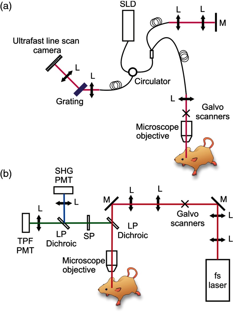
The OMAG imaging system used in this study is similar to the one reported in Ref. 17. A simplified systematic diagram is shown in Fig. 1(a). Briefly, a superluminescent diode (SLD) with a center wavelength of 1340 nm and bandwidth of 110 nm was employed as the light source delivering an axial resolution of in the air. An optical circulator was used to couple the light from the SLD into a fiber-based Michelson interferometer. A microscope objective lens with an 18-mm focal length was used to achieve lateral resolution. A 633-nm laser diode was used as a guiding beam to locate the imaging position. The light output from the interferometer was then directed to a home-made high-speed spectrometer, which employed a high-speed camera with a line scan rate of 92 kHz. The 3-D imaging was achieved using an X–Y galvanometer scanner. The light power exposed at the sample plane was . The system setup of the house-built multiphoton microscopy is schematically shown in Fig. 1(b). The output from a tunable (760–840 nm) 95 MHz femtosecond Ti–sapphire laser (Kapteyn–Murnane Laboratories Inc., Boulder, Colorado) was expanded with a telescope to match the optical aperture of the optical scanners. Two galvanometer scanners (GVS002, Thorlabs, Newton, New Jersey) were utilized to raster scan the laser. Acquired MPM images were of pixels with an acquisition time of 1.6 s per image. The image field-of-view (FOV) was . After the scanners, a scan and tube lens combination was used to further expand the beam to fill the rear aperture of a () long working distance () water immersion objective (LUMPLFLN60X/W, Olympus America Inc., Center Valley, Pennsylvania). A 665-nm excitation long-pass dichroic was equipped immediately after the objective lens to reflect the epi-directed multiphoton signals toward the detection arm. In the detection arm, a 650-nm short-pass emission filter was used to remove residual excitation light. A 405-nm dichroic beam splitter was used to separate and direct the second-harmonic generation and two-photon fluorescence signals to a pair of photomultiplier tube modules (H9433MOD-03, Hamamatsu Corp., Bridgewater, New Jersey). In this study, the wavelength for MPM imaging was 800 nm and the power after the objective was .
Fig. 1.
Systematic diagram of (a) OMAG and (b) MPM imaging systems. L: lens; M: mirror; SLD: superluminescent laser diode; LP Dichroic: long-pass dichroic beamsplitter.
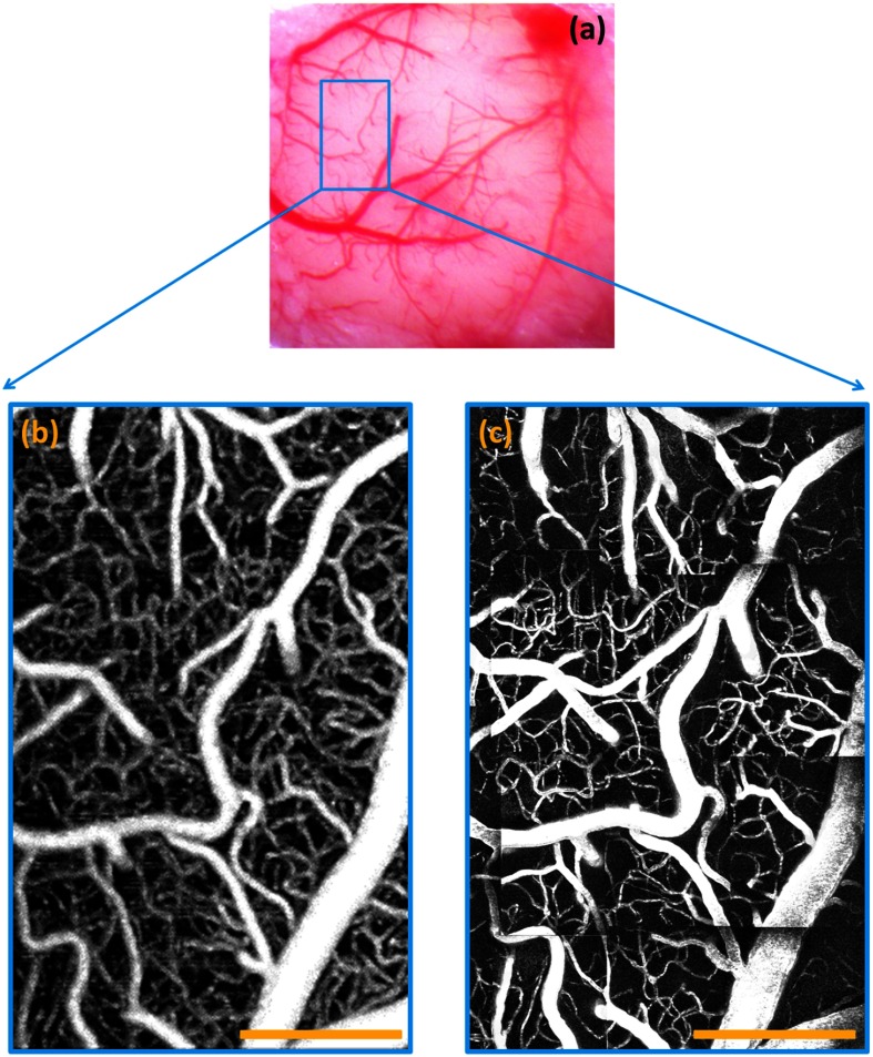
A standard white-light microscopic image of the mouse brain is shown in Fig. 2(a). The OMAG vascular image was taken from the area labeled with a blue rectangle in Fig. 2(a), and is shown in Fig. 2(b). In order to compare with the MPM imaging, which has a penetration limitation , the OMAG image was displayed as a maximal projection view of a depth range from the surface of the cortex to beneath. All the OMAG signals outside this depth range were discarded. A clear vasculature network can be visualized. Since MPM has a much smaller image FOV compared to OMAG, the MPM image shown in Fig. 2(c) is stitched from several small MPM images and covers the same area as the OMAG. The MPM image is displayed as a maximal projection view of the same depth range with a step size of every . We find a close correlation between OMAG and MPM images.
Fig. 2.
Vascular images of mouse brain. (a) White-light microscope image of the mouse brain (); OMAG image of mouse brain from the region labeled by the blue rectangle in (b); (c) MPM image of mouse brain from the same area as OMAG. Scale bar: .
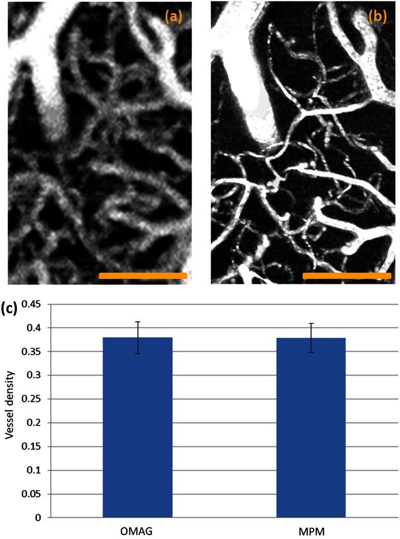
In order to better cross-validate the image results acquired using the two techniques, quantitative analysis was performed. In total, six ROIs that contain rich capillaries were first chosen. Representative zoom-in OMAG and MPM vascular images are shown in Figs. 3(a) and 3(b). Vessel density of the selected ROIs was then calculated for both OMAG and MPM images. To calculate the vessel density for each image, segmentation algorithm is applied.21 Briefly, in this method, images are skeletonized and binarized from which the vessel density is calculated by dividing the number of pixels with a value of one with the total pixel number. The mean and standard deviation were then calculated. As shown in Fig. 3(c), the vessel density calculated using OMAG image shows a very slight difference compared to MPM image, which could be due to the worse image resolution of OMAG. A student -test was then performed with its result of a -value (), indicating a lack of significant difference between the vessel density derived from the two techniques. Based on the statistical analysis, we believe that OMAG is able to accurately visualize most of the capillaries.
Fig. 3.
Quantification of the OMAG and MPM images for mouse brain. (a) Representative zoom-in OMAG image of the selected region-of-interest (ROI); (b) representative zoom-in MPM image of the same ROI; (c) the mean of vessel density calculated from six selected ROIs. Error bar: standard deviation. Scale bar: .
The capability of resolving two capillaries depends on the image resolution. Therefore, when the distance between two capillaries is smaller than (the image resolution of our system), the system will not able to successfully resolve them. We did not test the smallest capillary that the system can resolve, but by comparing with the MPM image, we believe that the size limitation is around . Although the resolution of OMAG may not be able to 100% resolve two closely packed tiny capillaries, it is still capable of visualizing most of the capillaries because there is always interstitial tissue space between any capillary vessels that innervate the living tissue. In addition, because of the limited resolution of OMAG, those tiny capillaries, which have a diameter smaller than the resolution of OMAG, may appear larger than their physical diameters, which may explain the slightly higher vessel density result seen in Fig. 3(c). Therefore, quantification of the diameter of those tiny capillaries may not be accurate enough. However, quantification of most capillaries and bigger vasculature using OMAG is still valid. One significant advantage of OMAG is that vasculature visualization can be achieved without external labeling, attractive for future clinical applications. To better characterize the accuracy of OMAG for quantifying vessel diameters, the physical diameter of the vessels should be measured in future studies.
In conclusion, we have validated the capability of OMAG in visualizing capillaries using MPM. OMAG images showed great consistency with the image results acquired from MPM. The vessel density of the tested area matched well with the MPM results. Therefore, we believe that OMAG can be utilized to visualize and quantify tissue vasculatures.
Acknowledgments
This work was supported by research grants from the National Institutes of Health (Grant Nos. RO1EB009682 and RO1HL093140) and the Canadian Institutes of Health Research (Grant No. MOP130548). The funders had no role in study design, data collection and analysis, decision to publish, or preparation of the manuscript.
Biography
Biographies of the authors are not available.
References
- 1.Hunt Thomas K., Wound Healing and Wound Infection: Theory and Surgical Practice, Appleton-Century-Crofts, New York: (1980). [Google Scholar]
- 2.Clark R. A., The Molecular and Cellular Biology of Wound Repair, Springer, New York: (1996). [Google Scholar]
- 3.Carmeliet P., “Angiogenesis in life, disease and medicine,” Nature 438(7070), 932–936 (2005). 10.1038/nature04478 [DOI] [PubMed] [Google Scholar]
- 4.Helbich T. H., et al. , “Noninvasive assessment of wound-healing angiogenesis with contrast-enhanced MRI,” Acad. Radiol. 9(1), S145–S147 (2002). 10.1016/S1076-6332(03)80423-3 [DOI] [PubMed] [Google Scholar]
- 5.Martin P., “Wound healing--aiming for perfect skin regeneration,” Science 276(5309), 75–81 (1997). 10.1126/science.276.5309.75 [DOI] [PubMed] [Google Scholar]
- 6.Piotto D. G. P., et al. , “Laser Doppler imaging for assessment of microcirculation in juvenile systemic sclerosis,” Rheumatology 53(1), 72–75 (2014). 10.1093/rheumatology/ket288 [DOI] [PubMed] [Google Scholar]
- 7.Debbabi H., et al. , “Noninvasive assessment of endothelial function in the skin microcirculation,” Am. J. Hypertens. 23(5), 541–546 (2010). 10.1038/ajh.2010.10 [DOI] [PubMed] [Google Scholar]
- 8.Lockwood G., et al. , “Beyond 30 MHz [applications of high-frequency ultrasound imaging],” IEEE Eng. Med. Biol. Mag. 15(6), 60–71 (1996). 10.1109/51.544513 [DOI] [Google Scholar]
- 9.Barrett T., et al. , “Macromolecular MRI contrast agents for imaging tumor angiogenesis,” Eur. J. Radiol. 60(3), 353–366 (2006). 10.1016/j.ejrad.2006.06.025 [DOI] [PubMed] [Google Scholar]
- 10.Vasquez S. X., et al. , “Optimization of microCT imaging and blood vessel diameter quantitation of preclinical specimen vasculature with radiopaque polymer injection medium,” PloS One 6(4), e19099 (2011). 10.1371/journal.pone.0019099 [DOI] [PMC free article] [PubMed] [Google Scholar]
- 11.Huang D., et al. , “Optical coherence tomography,” Science 254(5035), 1178–1181 (1991). 10.1126/science.1957169 [DOI] [PMC free article] [PubMed] [Google Scholar]
- 12.Wang R. K., et al. , “Three dimensional optical angiography,” Opt. Express 15(7), 4083–4097 (2007). 10.1364/OE.15.004083 [DOI] [PubMed] [Google Scholar]
- 13.An L., Qin J., Wang R. K., “Ultrahigh sensitive optical microangiography for in vivo imaging of microcirculations within human skin tissue beds,” Opt. Express 18(8), 8220–8228 (2010). 10.1364/OE.18.008220 [DOI] [PMC free article] [PubMed] [Google Scholar]
- 14.Wang R. K., Hurst S., “Mapping of cerebro-vascular blood perfusion in mice with skin and skull intact by optical micro-angiography at wavelength,” Opt. Express 15(18), 11402–11412 (2007). 10.1364/OE.15.011402 [DOI] [PubMed] [Google Scholar]
- 15.Jia Y., Alkayed N., Wang R. K., “Potential of optical microangiography to monitor cerebral blood perfusion and vascular plasticity following traumatic brain injury in mice in vivo,” J. Biomed. Opt. 14(4), 040505 (2009). 10.1117/1.3207121 [DOI] [PMC free article] [PubMed] [Google Scholar]
- 16.An L., et al. , “High-resolution wide-field imaging of retinal and choroidal blood perfusion with optical microangiography,” J. Biomed. Opt. 15(2), 026011 (2010). 10.1117/1.3369811 [DOI] [PMC free article] [PubMed] [Google Scholar]
- 17.Wang H., Baran U., Wang R. K., “In vivo blood flow imaging of inflammatory human skin induced by tape stripping using optical microangiography,” J. Biophoton. (2014). 10.1364/OE.15.011402 [DOI] [PMC free article] [PubMed] [Google Scholar]
- 18.Wang H., et al. , “Multimodal optical imaging can reveal changes in microcirculation and tissue oxygenation during skin wound healing,” Lasers Surg. Med. 46(6), 470–478 (2014). 10.1002/lsm.22254 [DOI] [PMC free article] [PubMed] [Google Scholar]
- 19.Zhi Z., et al. , “Volumetric and quantitative imaging of retinal blood flow in rats with optical microangiography,” Biomed. Opt. Express 2(3), 579–591 (2011). 10.1364/BOE.2.000579 [DOI] [PMC free article] [PubMed] [Google Scholar]
- 20.Baran U., Shi L., Wang R. K., “Capillary blood flow imaging within human finger cuticle using optical microangiography,” J. Biophoton. (2013). 10.1002/jbio.201300154 [DOI] [PMC free article] [PubMed] [Google Scholar]
- 21.Reif R., et al. , “Quantifying optical microangiography images obtained from a spectral domain optical coherence tomography system,” J. Biomed. Imaging 2012(9), 509783 (2012). 10.1155/2012/509783 [DOI] [PMC free article] [PubMed] [Google Scholar]


