Abstract
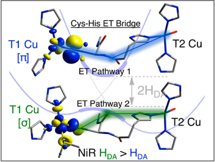
Type one (T1) Cu sites deliver electrons to catalytic Cu active sites: the mononuclear type two (T2) Cu site in nitrite reductases (NiRs) and the trinuclear Cu cluster in the multicopper oxidases (MCOs). The T1 Cu and the remote catalytic sites are connected via a Cys-His intramolecular electron-transfer (ET) bridge, which contains two potential ET pathways: P1 through the protein backbone and P2 through the H-bond between the Cys and the His. The high covalency of the T1 Cu–S(Cys) bond is shown here to activate the T1 Cu site for hole superexchange via occupied valence orbitals of the bridge. This covalency-activated electronic coupling (HDA) facilitates long-range ET through both pathways. These pathways can be selectively activated depending on the geometric and electronic structure of the T1 Cu site and thus the anisotropic covalency of the T1 Cu–S(Cys) bond. In NiRs, blue (π-type) T1 sites utilize P1 and green (σ-type) T1 sites utilize P2, with P2 being more efficient. Comparing the MCOs to NiRs, the second-sphere environment changes the conformation of the Cys-His pathway, which selectively activates HDA for superexchange by blue π sites for efficient turnover in catalysis. These studies show that a given protein bridge, here Cys-His, provides different superexchange pathways and electronic couplings depending on the anisotropic covalencies of the donor and acceptor metal sites.
1. Introduction
Type one (T1) copper proteins1 are a highly studied group of metal-containing ET active sites—one reason being their adaptability, which allows them to carry out ET in a broad range of biological functions and environments.2−6 T1 active sites are built from a conserved equatorial trigonal ligand field, which is constituted by a very short Cu–S(Cys) bond and two normal Cu–N(His) bonds.7−9 In this roughly trigonal metal environment, the axial ligand has been the subject of much research effort and can be a S(Met) residue (e.g., plastocyanin (Pc)9 and azurin (Az)10), O(Gln) (e.g., stellacyanin (St)11), or non-coordinating, hydrophobic residues (Ile/Phe) (e.g., fungal laccases12,13). The trans-axial position can be occupied by a carbonyl group provided by the protein backbone (e.g., Az); however, due to the long O···Cu distance of ∼3 Å, it does not interact covalently with the Cu but contributes electrostatically.14 Alternatively, this position can be shielded by bulky, hydrophobic residues, which have a tendency to rotate the carbonyl ligand away from the Cu (e.g., fungal laccases).
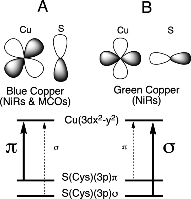
T1 Cu proteins initially attracted attention due to their unique spectral features.6,15,16 The geometric structure of the T1 site, as outlined above, exerts a strong influence on its electronic structure. Two major classes of T1 sites have been identified on the basis of their spectral features: blue (BC) and green copper (GC) sites. The classic BC proteins, Pc and Az, exhibit an intense S(Cys)(3pπ) → Cu2+ ligand-to-metal charge-transfer (LMCT) transition at ∼600 nm (ε ≈ 5000 M–1 cm–1),17 which imparts the characteristic blue color to the protein and a small parallel 63,65Cu hyperfine coupling (A||) in electron paramagnetic resonance (EPR) spectroscopy.18,19 These have been shown to reflect the highly covalent nature of the Cu(II)(3dx2–y2)–Sπ(Cys) bond (vide infra). Well-defined structural perturbations transform the T1 site from blue to green in color. This transformation has been termed the coupled distortion coordinate20,21 and includes (1) a decrease in the axial Cu(II)–S(Met) distance, (2) an increase in the Cu(II)–S(Cys) distance, and (3) a rotation of the S(Met)–Cu–S(Cys) plane into the N(His)–Cu–N(His) plane, which is a tetragonal Jahn–Teller (eu) rotation from ∼tetrahedral (blue) to ∼tetragonal (green). This protein induced change in geometry results in a rotation of the ground state wave function from π- to σ-bonding between the Cu and the S(Cys) (Figure 1). The two wave functions give rise to significantly different intensity distributions between the S(Cys)(3pπ) and S(Cys)(3pσ) → Cu2+ LMCT transitions in absorption (abs) (Figure 1). Thus, the electronic structure and spectral features, which are dominated by the Cu–S(Cys) bonding interaction, are highly anisotropic in nature, switching from π- to σ-types through the interaction of the T1 Cu site with the protein environment.22,23
Figure 1.
Orbital interactions for a blue π (A) and a green σ (B) T1 Cu site in NiRs and MCOs. Strong π overlap between the Cu(3dx2–y2) and SCys(3p) orbitals (A) results in strong π and weak σ charge-transfer intensity in absorption. Good σ overlap (B) reverses the intensity distribution between π and σ CT.
These unique spectral features reflect the high degree of covalency of the Cu(II)–S(Cys) bond of the T1 site. The degree of electron delocalization over the Cu(II)–S(Cys) bond of T1 sites has been directly measured using a combination of Cu L-edge and S K-edge X-ray absorption spectroscopy,19,24 which are direct probes of the β-lowest unoccupied molecular orbital (β-LUMO). This is the MO responsible for ET and is therefore referred to as the redox-active molecular orbital (RAMO). At least for Pc, previous studies have hypothesized that the high π-type covalency of the T1 Cu bond activates the site for long-range ET.6,25
Two enzyme classes contain T1 sites, the nitrite reductases (NiRs) and multi-copper oxidases (MCOs).26 NiR enzymes are involved in bacterial denitrification and carry out the one-electron reduction of NO2– to NO and H2O. The MCOs couple the oxidation of a wide variety of substrates to the reduction of O2 to H2O.26 Much of the recent work on MCOs has been directed toward using enzymes with high T1 Cu reduction potentials (E0’s) as cathodes in biofuel cells.27,28 Both NiRs and MCOs have T1 Cu sites that are connected via a protein-derived Cys-His bridge to a catalytic metal active site: a mononuclear Cu (type two (T2)) site in the NiRs and a trinuclear copper cluster in the MCOs. The Cu-to-Cu ET pathway construct in NiR is given in Figure 2.
Figure 2.
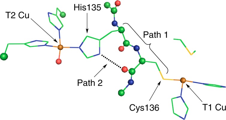
Structure of the Cys-His pathway connecting type one (T1) and type two (T2) Cu sites in NiR. The protein backbone is shown as spheres, and residue R groups are given as lines (PDB ID: 1NIA).
There are a number of important issues to consider in terms of the structure of the Cys-His pathway and the T1 sites in NiRs and MCOs. First, the Cys-His pathway is considered to contribute two individual pathways: through the S(Cys) R group, into the protein backbone, and out the T2 Cu bonded His residue (pathway 1 (P1)), and through the S(Cys) R group, through the S(Cys) amide functionality to an H-bond jump (dotted line in Figure 2), and out the T2 Cu bonded His residue (pathway 2 (P2)). In principle, both of these pathways can contribute to ET. It is of further interest to consider that NiRs have both blue and green T1 Cu sites while the MCOs only have blue T1 Cu sites. The difference between blue and green sites, as mentioned above, involves a very different interaction between the Cu(3dx2–y2) orbital and the π and σ orbitals of the S(Cys) ligand of the molecular bridge. Therefore, the electronic structure of the T1 site could also influence ET to the catalytic site.
Three parameters within the framework of Marcus theory29 govern the rates of intramolecular ET between the T1 and T2 Cu sites: ΔG0, the driving force; λ, the reorganization energy, which can be divided into contributions from the T1 and T2 Cu (λT = λT1/2 + λT2/2); and HDA, the electronic coupling matrix element. During catalysis carried out by NiR and MCO enzymes, all of these elements work concertedly to drive the reaction. While past research has largely focused on ΔG0 and the associated potentials of the Cu sites as well as reorganization energies,6,30−33 the focus of this study is on HDA.
Here, density functional theory (DFT) calculations are coupled to a range of perturbations within structural models of NiR to investigate the contributions to HDA from the Cys-His pathway. These contributions include (1) the Cys-His protein fold connecting the T1 and T2 Cu sites; (2) the nature of the high degree of covalency of the Cu(II)–S(Cys) bond and its contribution to activating electron or hole superexchange pathways; (3) the anisotropy of the T1 Cu(II)–S(Cys) bond and its effect on coupling into superexchange pathways; and (4) the relative efficiencies of P1 and P2. Some existing experimental data on intramolecular ET in NiRs are put into context of these results. While multiple ET pathways to multiple Cu sites are present in the MCOs and only one Cys-His pathway is present in the NiRs, a comparison between the analogous Cys-His bridge of the MCOs and NiRs indicates that a specific second-sphere interaction is capable of tuning HDA differently for blue vs green T1 Cu sites. Finally, the calculated HDA is related to the Heisenberg–Dirac–Van Vleck exchange coupling, J, of the two Cu(II) centers connected via the Cys-His bridge. Knowledge of J allows for an experimental estimate of HDA as both relate to the same superexchange pathway.
2. Computational Methodology
DFT calculations were carried out using the Gaussian 09 program.34 Molecular orbital compositions and fragment analyses were determined using the QMForge program35 (c2 and Mulliken population analyses (CSPA and MPA, respectively)), orbital overlaps were calculated using the AOMix program,36,37 and all orbital surfaces were generated using the β-LUMO program.38 For all Results and Analysis sections, DFT calculations were carried out using the B(38HF)P8639−42 functional (spin unrestricted), in combination with a triple-ζ TZVP43 basis set on all atoms. This amount of HF mixing was chosen because, in the absence of the protein environment, it gives the correct active-site covalency (e.g., ∼42%S(π) in the P–P1–P2–B model in section 3.1.3), which will be seen to be important in this study. Since point charges are used as described below, this precludes employing the polarized continuum model in calculating HDA. The geometries for the calculations were derived from an X-ray crystal structure of NiR (PDB ID: 1NIA,44Achromobacter cycloclastes (A.c.)). Because several different models are compared in sections 3.1 and 3.2, we have mostly employed “idealized” oxidized T1 (blue and green) and T2 geometries at reasonable Cu(II) bond distances. The important structural parameters are in Supporting Information Table S1 and are described in more detail in the text. Further, in section 3.1.2, the geometries of the T1 site were partially optimized to properly estimate the effect of second-sphere perturbations on the T1 active site and thus covalency on HDA, and in section 3.2.1 the T2 Cu site was varied to reflect the geometry in the crystal structure.
To calculate HDA, we have used the approach described in ref (45−51). This involves using either a 2Cu(II) (triplet) or 2Cu(I) electronic structure. Either the β-LUMOs (2Cu(II) case) or the β-HOMOs (2Cu(I) case) are brought into and out of resonance using point charges of equal magnitude and opposite sign. These were placed along the Cu–S(Cys) bond (for the T1 Cu) and along the Cu–N1(His) bond (for the T2 Cu) and at a distance of 8.0 Å from the Cu ion. Variation in the value of the charge resulted in the energetic stabilization or destabilization of the molecular orbitals of the T1 and T2 Cu sites. Near the resonance point, where the energies of the two molecular orbitals become similar, they mix due to configuration interaction (CI), and the closest energy splitting (i.e., at resonance) is taken to be 2HDA.
In the Discussion, J is calculated as the energy splitting between the 2Cu(II) triplet and broken-symmetry singlet states (spin-corrected):52
| 1 |
3. Results and Analysis
3.1. Structural and Electronic Contributions to HDA
3.1.1. Type One–Type Two Electronic Coupling: Pathway 1
Specific factors contributing to electronic coupling between T1 and T2 sites through the Cys-His P1 are considered here (IN1A numbering, Figure 2). It is found below that HDA through P1 is strongly dependent on bridge conformation. For blue (π-type) sites, the protein fold of P1 activates a superexchange pathway capable of coupling blue T1 Cu (π) and T2 Cu (σ) sites. The opposite is observed for a superexchange pathway coupling green T1 Cu (σ) and T2 Cu (σ), where P1 is deactivated by the local protein conformation.
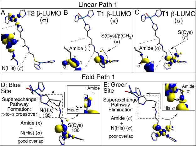
Four structural models have been considered here. Two conformations of P1 were evaluated: (1) a linearized model, in which P1 has been extended into an idealized all-trans geometry (Figure 3, left); and (2) P1 in the local protein fold, as found in the X-ray crystal structure of NiR (Figure 3, middle). In addition, for each conformation of P1, the T1 Cu site is varied between a blue (π-type) and a green (σ-type) site (Figure 1). The individual models are referred to as follows: (1) L–P1–B (i.e., linear bridge, P1 only, blue T1 Cu site); (2) P–P1–B (i.e., protein bridge, P1 only, blue T1 Cu site); (3) L–P1–G; and (4) P–P1–G, where (3) and (4) are the same as (1) and (2) except with a green (σ) T1 Cu site. Geometric parameters of the four models are given in the Supporting Information, Table S1. For the blue site, two N(His) ligands are bonded to the Cu in a trigonal fashion giving a π-type ground state wave function. The green model has an additional strong Cu–S(Met) interaction and a tetragonal geometry. Thus, these models represent the limits of the coupled distortion coordinate. On the acceptor side of the Cys-His pathway is the T2 Cu site. In the models considered in this section, the T2 site is constructed as having a distorted square planar geometry, which results in four σ bonds to the T2 Cu (T2(σ)). Representative β-LUMOs for the T2 Cu(II) and the blue and green T1 Cu(II) are given in Figure 4A–C.
Figure 3.
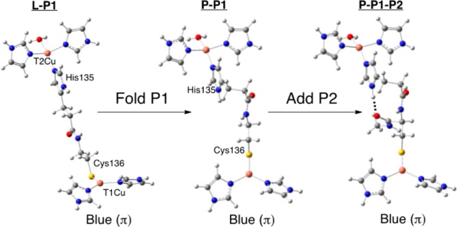
Structures and labeling for the idealized linear and protein bridge models. The H-bond in pathway 2 is shown as a dotted line in the structure on the right.
Figure 4.
Superexchange pathways for electronic coupling between the T1 and T2 Cu active sites in linear and protein models: (A–C) linear P1 T2, T1 blue, and T1 green, respectively; (D,E) protein fold blue and green, respectively.
HDA is calculated to be 0.7 and 22.7 cm–1 for the L–P1–B and L–P1–G models, respectively, and can be related to the orbital symmetries of the T1 and T2 β-LUMOs (Figure 4A). Note that the T2 β-LUMO is of the σ-type, while the blue and green T1 β-LUMOs are of the π- and σ-type, respectively (Figure 4B and 4C). Therefore, in the limit that the linear models are Cs, the β-LUMOs of the T1 and T2 sites in the L–P1–B model are orthogonal and HDA = 0.00 cm–1 (defined here as π-/σ-type T1/T2 coupling). Conversely, orbital overlap through Cys-His pathway in the L–P1–G model is maximized due to the σ nature of both the T1 and T2 sites, respectively (defined here as σ-/σ-type T1/T2 coupling), and results in a large HDA (22.7 cm–1). HDA for L–P1–B is not 0.00 cm–1 (0.7 cm–1) due to the placement of the N(His) ligands on the T1 Cu site as they are found in the protein structures, which results in some σ character in this blue π model. Modification of the T1 and T2 ligands to ammines (NH3) and maintaining Cs symmetry abolishes the S(pσ) character in the linear blue model and HDA = 0.00 cm–1 (Supporting Information, Table S2, top; see also Supporting Information, Figure S1, for structures).
The above results indicate that the intrinsic electronic coupling between a blue T1 Cu(II) and a T2 Cu(II) (π-/σ-type) is zero in the absence of additional perturbations, even with a highly covalent Cu(II)–S(Cys) bond (i.e., ∼45% S(p) character in the β-LUMO). Conversely, the intrinsic electronic coupling between a green T1 Cu(II) and a T2 Cu(II) (σ-/σ-type) is high in the all-trans configuration of the Cys-His pathway despite the lower total S(p) character (∼18% in the β-LUMO) relative to the blue site. Therefore, not only is it necessary to have a covalent Cu(II)–S(Cys) bond, but the covalency should be of the correct symmetry to couple to specific fragment orbitals of the bridge. This is related to the nature of the superexchange pathway and is analyzed below.
The linear bridge considered above was “refolded” into the local protein fold in NiR (Figure 3, left to middle, corresponding to P–P1–B and P–P1–G). No changes are made to the T1 and T2 Cu(II) sites. Transforming the bridge in P–P1–B increases HDA to 8.7 cm–1 (relative to 0.7 cm–1) and decreases it to 1.2 cm–1 for P–P1–G (relative to 22.7 cm–1). The origins of these changes are analyzed below.
The changes in HDA upon going to the protein P1 are not related to changes in T1 or T2 active-site electronic structure, but relate to the nature of the T1/T2 interaction (coupling) through the bridge (i.e., no change in T1/T2 electronic structure). Despite maintaining the local π-/σ-type (P–P1–B) and σ-/σ-type (P–P1–G) T1/T2 coupling, the π-/σ-coupling is now more favorable than the σ-/σ-type and has a larger HDA (8.7 vs 1.2 cm–1, respectively), which is opposite the trend in the linear models. Thus, for the blue site, the Cys-His bridge in the protein results in a π-to-σ crossover.
The activation of HDA for the blue site and deactivation for the green site can be understood by expanding the contours of the blue and green T1 β-LUMOs. The T1 wave function extends through the S(Cys) amide functionality formed between Cys136 and His135. For the blue site, the amide orbital is out-of-plane (π); for the green site it is in-plane (σ) (zoom-ins indicated by dotted lines in Figure 4B,C). Expansion of the T2 β-LUMO (dotted lines in Figure 4A) indicates that the T2 Cu wave function extends into the σ orbital of the N(His) ligand. Comparison of Figure 4A,C shows the formation of a good superexchange pathway between the green σ T1 Cu and σ T2 Cu sites through the all-trans conformation of the linearized P1. Upon folding, a right angle is created in the Cys136 and His135 connection (Figure 4D,E, arrows). This fold in the pathway greatly decreases the superexchange pathway between the green T1 Cu and T2 Cu sites and activates the superexchange pathway in the blue π T1 model. The 135 N(His) σ orbital is rotated to stack alongside the amide functionality of Cys-His pathway (shown as dotted lines in Figure 4D). This creates orbital overlap between the N(His) σ orbital and the S(Cys) amide out-of-plane π orbital, which forms the π-to-σ crossover in P1 for the blue site in the NiR protein Cys-His fold and defines the superexchange pathway for the P–P1–B model (Figure 4D, inset). Specific atom contributions to this pathway are considered below.
3.1.2. Covalency Activated Superexchange
It was previously proposed that the high covalency of the Cu–S(Cys) bonds can activate sites for directional long-range ET.25,55 Here, we evaluate this idea using P–P1–B by tuning the covalency of the T1 Cu(II)–S(Cys) bond. It is found below that the calculated HDA varies linearly with Cu–S(Cys) covalency, which indicates its important role in activating specific superexchange pathways for long-range ET. Additionally, fragment analyses define the orbital superexhange pathway for blue T1 Cu sites and demonstrate that a hole-transfer mechanism (as opposed to electron-transfer) is dominant.
We have previously shown that active H-bonds (i.e., those that interact with and are in the plane of the lobes of the 3p(π) Cys orbital) tune down the covalency of the T1 Cu–S(Cys) bond.56 Here, two partial point charges (varied from 0.00 to 0.75 in increments of 0.25; the T1 site is partially optimized at each point) have been placed in the plane of the Cu–S(Cys) π-bond to model active H-bonds. Increasing the charge from 0.00 to 0.75 decreases the covalency of the T1 Cu(II)–S(Cys) bond by ∼17%S(p) (MPA) (∼10%S(p) CSPA) (Table 1) and decreases HDA by 3.0 cm–1 (from 8.3 to 5.3 cm–1). Plots of HDA versus S(p) character for both MPA- and CSPA-derived contributions yield linear relationships with high values of R2 (0.939 and 0.999, respectively, Table 1). The y-intercepts were set to zero in the fits and yield slopes of 0.22 (Mulliken) or 0.28 (CSPA) cm–1/%S(p). The correlation between HDA and S(p) character is plotted, normalized to zero charge, in Figure 5 and indicates that HDA and covalency vary in a linear fashion. In context of Marcus theory, covalency will have a large impact on kET as it varies as HDA2 and consequently follows the square of the S contribution (or an orbital coefficient to the power of 4) of the T1 Cu(II)–S(Cys) bond, which can be obtained experimentally using S K-edge XAS.19 This is covalency activated superexchange and enables the T1 Cu site to carry out long-range ET.
Table 1. Parameters for Covalency-Activated HDA for the P–P1–B Model.
| MPA-derived orbital contributions (%) |
CSPA-derived orbital contributions (%) |
||||
|---|---|---|---|---|---|
| point charge | T1 Cu(d) |
T1 S(p) |
T1 Cu(d) |
T1 S(p) |
HDA (cm–1) |
| 0.00 | 47.42 | 39.23 | 39.89 | 29.85 | 8.3 |
| 0.25 | 52.36 | 33.28 | 44.4 | 26.40 | 7.3 |
| 0.50 | 57.07 | 27.16 | 48.60 | 22.52 | 6.2 |
| 0.75 | 60.72 | 22.47 | 51.83 | 19.39 | 5.3 |
| Δ | 13.30 | 16.76 | 11.94 | 10.46 | 3.0 |
| slopea (cm–1/%S(p)) | 0.22 | 0.28 | 0.25b | ||
| R2 (linear fit) | 0.939 | 0.999 | |||
Linear fit performed with y-intercept set to zero for T1 S(p) vs HDA.
Average of MPA- and CSPA-derived contributions.
Figure 5.
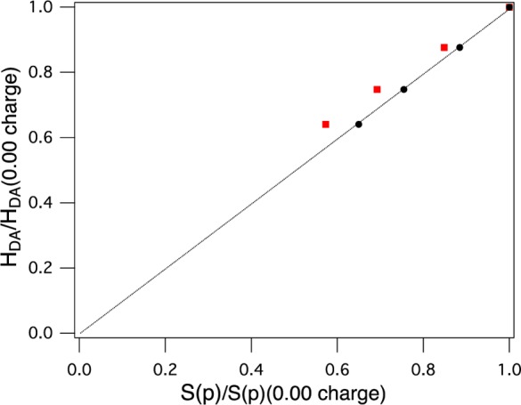
Covalency-activated HDA: linear correlation of HDA with covalency (%S(p)). The line is drawn for a slope of one between HDA and covalency. Values are normalized to no charge (red squares, MPA-derived contributions; black circles, CSPA-derived contributions).
The mechanism of superexchange (i.e., electron vs hole transfer) for ET between T1 and T2 Cu sites has also been evaluated. The literature has approached the problem of electron and hole transfer by using either the doubly oxidized or doubly reduced forms of the donor and acceptor.47,50,51 In the former case, the ΔE(LUMO/LUMO+1) is calculated, while in the latter, the ΔE(HOMO/HOMO–1) is calculated upon bringing the corresponding orbitals into and out of resonance. The results of both methods are compared for the P–P1–B model.
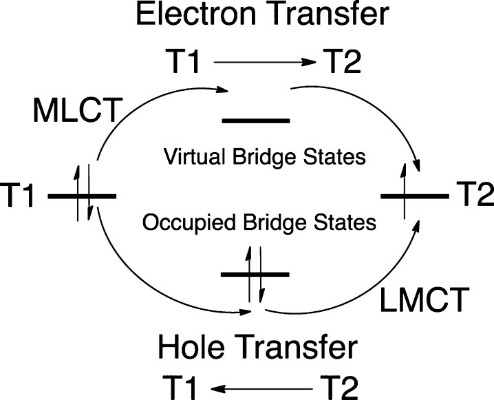
The calculated HDA values for the 2Cu(II) and 2Cu(I) P–P1–B models are similar (8.7 and 9.2 cm–1, respectively). A schematic for electron vs hole transfer between a reduced T1 and oxidized T2 site is given in Figure 6. A hole can be transferred from the T2 to the T1 via occupied valence bridge states (Figure 6, bottom) and can be initiated via an LMCT (labeled in Figure 6). Electron transfer, conversely, is mediated via virtual bridge conduction states (Figure 6, top) and can be initiated via a metal-to-ligand CT (MLCT, labeled in Figure 6). These mechanisms can be differentiated by the nature of the bridge states involved in superexchange. This has been evaluated through fragment orbital analyses on the 2Cu(II) (2Cu(I)) model, which projects the bridge orbitals onto the LUMO and LUMO+1 (HOMO–1 and HOMO). This was done when the RAMOs were out of and in resonance. At resonance, the occupied bridge orbitals of the T1 Frag1_53 and T2 Frag1_47 Cu are mixed in equal proportions, and the superexchange pathway of the bridge is formed from the mixing between these bridge orbitals (Figure 7 and Supporting Information, Table S4). Analogous results were obtained for the 2Cu(I) model and no evidence for additional mixing of virtual bridge orbital character was observed (Supporting Information, Tables S4 and S5 and text). Therefore, a hole superexchange mechanism is dominant for T1 Cu sites.
Figure 6.
Diagram of hole vs electron superexchange mechanisms. LMCT and MLCT, which initiate these processes, are labeled.
Figure 7.
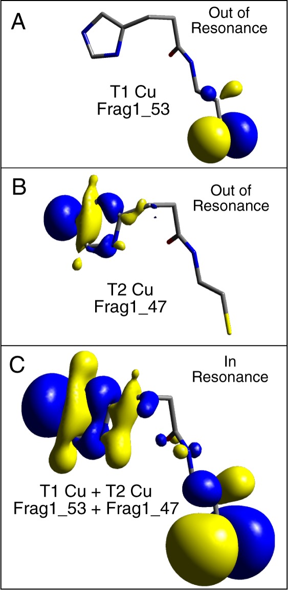
Occupied valence fragment molecular orbitals of (A) T1 Cu S(Cys) π (Frag1_53) and (B) T2 Cu N(His) σ (Frag1_47) out of resonance and (C) in resonance. Isovalues: (A) 0.050, (B) 0.050, and (C) 0.015.
3.1.3. Anisotropic Covalency Contributions to Selecting Superexchange Pathways
In the above, P1 has been considered; however, the Cys-His pathway also contains P2, which can potentially contribute to ET. P2 is composed of an H-bond between the carbonyl of Cys136 and the N–H unit of the T2 Cu His135 (Figure 2, A.c. numbering). In this section, models include P2 as well as P1 in the native protein Cys-His orientation and are referred to as P–P1–P2–B and P–P1–P2–G for blue and green T1 Cu sites, respectively (Figure 3, middle to right). No other perturbations have been added, and the T1 and T2 Cu sites are structurally identical to those used above. The differences between blue (π) and green (σ) T1 Cu site superexchange pathways and their relative efficiencies, are elucidated below. These differences are further shown to derive from the anisotropic nature of the Cu(II)–S(Cys) (π vs σ) bond, which results in different HDA values.
HDA values for P–P1–P2–B and P–P1–P2–G are calculated to be 6.9 and 16.4 cm–1, respectively (N–O H-bond distance ∼2.8 Å). This is a slight decrease in HDA for the blue site relative to P–P1 (8.7 cm–1) and a large increase for the green site relative to P–P1 (1.1 cm–1). To quantitate the effect of P2 on HDA, the H-bond distance involving P2 was varied by rotation about the Cα–Cβ bond of the His residue (see Supporting Information, Figure S2). To account for potential changes in P1 superexchange due to this structural perturbation, it has also been applied to the P–P1 models.
The H-bond distance dependence of HDA for P–P1–P2–B is shown as black circles in Figure 8A (listed in Table 2). HDA decreases systematically with increase in H-bond distance. However, a plot of HDA for the P–P1–B model as a function of the same perturbation results in the same distance dependence, even in the absence of P2 (red circles, Figure 8A). The small decrease in HDA observed between the P–P1–B and P–P1–P2–B models can be accounted for by a small decrease in the covalency of the Cu(II)–S(Cys) bond (decreases by ∼6%S(p) (average between MPA- and CSPA-derived orbital contributions; see Supporting Information, Table S3)) upon addition of P2. Using the value of 0.25 cm–1/%S(p) gives an HDA = 8.3 cm–1 for the P–P1–P2–B (covalency corrected) relative to that for the P–P1–B model, 8.7 cm–1. Accounting for this covalency difference, there is a good correspondence to the P–P1–BHDA values in Figure 8A (red and blue circles, respectively). Therefore, the overall superexchange pathway for the P–P1–P2–B model does not change upon addition of P2 and is still dominantly through P1.
Figure 8.
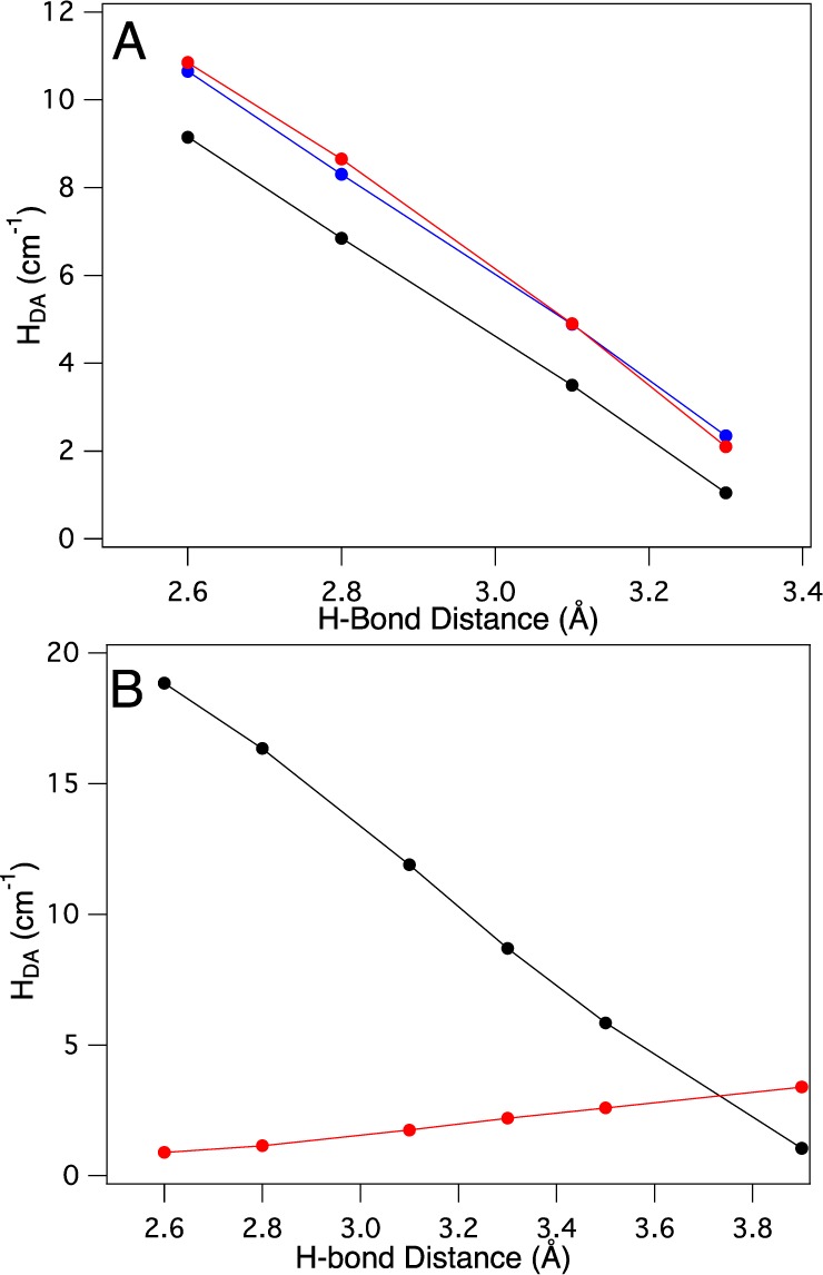
Distance and pathway dependence of HDA: (A) P–P1–B, red circles; P–P1–P2–B, black circles; P–P1–P2–B covalency corrected, blue circles; and (B) P–P1–G, red circles; P–P1–P2–G black circles.
Table 2. Pathway Distance Dependence of HDA for Green and Blue Models.
| blue |
green |
||||
|---|---|---|---|---|---|
| H-bond distance (Å) | P–P1–P2 | P–P1 | P–P1–P2a | P–P1–P2 | P–P1 |
| 2.6 | 9.2 | 10.9 | 10.7 | 18.9 | 1.0 |
| 2.8 | 6.9 | 8.7 | 8.3 | 16.4 | 1.1 |
| 3.1 | 3.5 | 4.9 | 4.8 | 11.9 | 1.7 |
| 3.3 | 1.1 | 2.1 | 2.3 | 8.7 | 2.2 |
| 3.5 | 5.9 | 2.6 | |||
| 3.9 | 1.1 | 3.4 | |||
| 2.8b | 2.2b | 5.8b | |||
| 2.8c | 5.5c | 0.4c | |||
Covalency corrected using a slope of 0.25 cm–1/%S(p).
T2(NiR).
T2(NiR), P2 rotates to 75°.
The H-bond dependence for the P–P1–G and the P–P1–P2–G models is given in Figure 8B and Table 2. HDA for the P–P1–P2–G model shows a strong H-bond distance dependence (black circles), while the distance dependence for P–P1–G (red circles) is limited. Note that the covalencies of the P–P1–G and P–P1–P2–G models are essentially the same, and thus no covalency correction is necessary. This distance dependence agrees well with the observation that HDA of the P–P1–P2–G (H-bond distance of 2.8 Å) and P–P1–G (no H-bond) models are 16.4 and 1.1 cm–1, respectively, and indicates that P2 contributes significantly to HDA for the green σ T1 site. This trend in H-bond distance dependence and HDA is opposite to those observed in Figure 8A for the analogous models with a blue π T1 Cu site. HDA for the green σ models is therefore dominantly through P2 superexchange. Thus, the blue and green sites utilize different superexchange pathways of the same molecular bridge, which results in significant differences in HDA.
Because of the location of the P2 amide relative to the T1 Cu(II)–S(Cys) bond, π vs σ T1 Cu bonding results in different coupling to the P2 amide. This is observed through successive expansions of the blue and green β-LUMOs (Figure 9; zoom-in on P2 indicated by dotted lines). The green σ β-LUMO shows orbital character on the oxygen atom involved in the P2 H-bond (Figure 9, right, bottom arrow); however, the β-LUMO of the blue π site at the same isosurface value (0.005) has no O character (Figure 9, left, bottom arrow). This difference in O-character is supported by population analyses (Supporting Information, Table S6; note the larger coefficients for the O(p)-character in green (∼0.04 vs blue ∼0.01, bolded)). The O(p) orbital contribution in the β-LUMO activates P2 for the green site, and, conversely, the lack of O(p) character precludes the blue site from utilizing the P2 H-bond for superexchange. This pathway selectivity is related to HDA and is analyzed below. Further analysis related to the molecular orbital basis for this difference is given in the Supporting Information, Figures S4 and S5 and supporting text.
Figure 9.
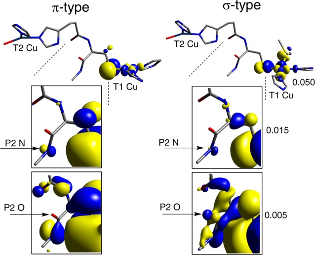
P2 O(p)-character activation: (left) blue π site and (right) green σ site.
Both P1 and P2 could be affected by protein dynamics. Considering a range of His rotation and H-bond distance variation for P1 and P2 within available thermal energy at room temperature, HDA can vary by ∼17% and ∼9% for the P–P1–P2–B and P–P1–P2–G models, respectively.
It is interesting to note that the HDA value for the green σ site is higher than that for the blue π site (16.4 cm–1 green vs 6.9 cm–1 blue) in NiR despite the lower covalency of the Cu(II)–S(Cys) bond (17.3%S(p) green vs 42.3%S(p) blue). In order to understand this difference, the relative efficiencies of P1 (blue) vs P2 (green) were evaluated.
The atoms involved in P1 and P2 pathways are indicated in Figure 10 with blue and green numbers, respectively. Starting from the common S(Cys) atom and proceeding to the common Nδ atom of the N(His) residue (Figure 10), P1 (blue) consists of four covalent bonds and several through-space or weak H-bonding interactions (dotted lines between C–P1, N–P1 and C-His, N-His, and H-His in Figure 10, where black labels through space and red, H-bonding). P2 (green) consists of two covalent bonds and two H-bonds (S(Cys),H = 3.06 Å; and N–His, O–P2 = 2.80 Å). Note that two possible pathways exist for the green T1 site to exit the S(Cys) (a and b in Figure 10); we focus on (a) due to the fact that the interaction between the P2 NH and S (dotted line in Figure 10, 3.06 Å) was shown above to activate O(p)-character in P2; however, both routes yield similar results. In order to compare the relative efficiencies, two factors are considered first: (1) the covalency of the Cu(II)–S(Cys) bond, which activates the superexchange pathway, and (2) the specific molecular orbital components of the pathway (i.e., number of chemical bonds, H-bonds, and through-space interactions). These two contributions for P1 and P2 can both be taken into account by noting the calculated total p-characters on the N–P1 and C–P1 atoms of P1 for the blue site and the O–P2 atom of P2 for the green site. The total p-characters on the C–P1 and N–P1 atoms are ∼0.05% and ∼0.08%, respectively, while the total p-character on the O–P2 atom is ∼0.04% (Supporting Information, Table S6, averages between Mulliken and CSPA). Interestingly, the higher contribution for P1 (∼0.13%) vs the contribution for P2 (∼0.04%) indicates that, only considering the two pathways up to these atoms, P1 would be the more efficient pathway. Note that the orbital coefficients of the acceptor T2 N(His) are the same for P1 and P2, and thus are not a factor. Therefore, the higher HDA for green relative to blue must be related to the relative orientations of the pathway components, which will govern the magnitude of the orbital interactions and overlaps. Importantly, the T2 N(His) σ orbital is directed along the N–H bond of the His ligand (Figure 10B), which is an optimal alignment for orbital overlap with the O(p) orbital of P2 and is at a short distance (∼2.8 Å heavy atom/heavy atom and ∼1.8 Å H–O). Alternatively, the through space interactions/weak H-bond of the N–H of the N(His) σ orbital with the out-of-plane amide π of P1 results in only moderate orbital overlap (Figure 10B) and long distances (∼3.0–3.1 Å). These differences in orbital orientations and distances favor the P2 (green σ) superexchange pathway. Indeed, the calculated absolute change in the overall orbital overlaps between the LUMO and LUMO+1 for P2 (including O–P2, N-His, and H-His) and P1 (including C–P1, N–P1, C-His, N-His, and H-His) in going from out of resonance to in resonance is ∼3 times larger for P2 than P1 (∼0.009 vs ∼0.003, respectively). Thus, the key differences between P2 and P1 superexchange efficiency are (1) the better orbital alignments and overlaps for P2 relative to P1 and (2) the shorter P2 H-bond vs longer P1 through-space/H-bond interactions (Figure 10B). In NiR, these factors contribute to a higher value of HDA for the green site (16.4 cm–1) relative to the blue site (6.9 cm–1), despite the lower covalency of the Cu(II)–S(Cys) bond in the former.
Figure 10.
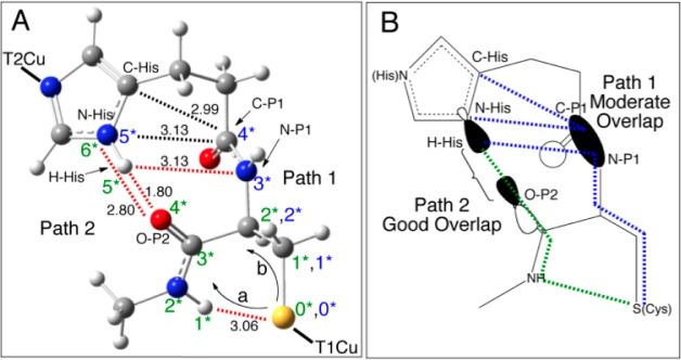
P1 and P2 superexchange pathways: (A) the atoms involved in P1 and P2 (black dotted lines indicate through-space interactions and red dotted lines indicate H-bonding) and (B) relative orbital overlaps for the molecular orbitals in P1 and P2 (blue and green dotted lines indicate interactions for the blue and green T1 sites, respectively).
Thus, anisotropy of the T1 Cu(II)–S(Cys) bond (π vs σ) allows for the coupling of the T1 site into different superexchange pathways of the Cys-His bridge, and, due to the relative orientations of the pathway components and orbitals, these pathways will have different efficiencies. HDA through the Cys-His pathway can therefore be varied by changing the geometric structure of the metal site.
3.2. Extension to Protein Sites
3.2.1. Nitrite Reductase
For the calculations presented in section 3.1, the T2 site was modeled as approximately square planar. This geometric structure has four σ bonds between the T2 Cu(3dx2–y2) and the 3N(His) and H2O ligands (Figure 11, top (T2(σ)). The T2 site was not allowed to vary. In this section we consider the extension of the P–P1–P2–B and P–P1–P2–G models to the actual structure of the T2 Cu site in NiR (T2(NiR)) and the effect on HDA. It is shown below that the covalencies of both the donor and acceptor Cu sites play important roles in intramolecular ET.
Figure 11.
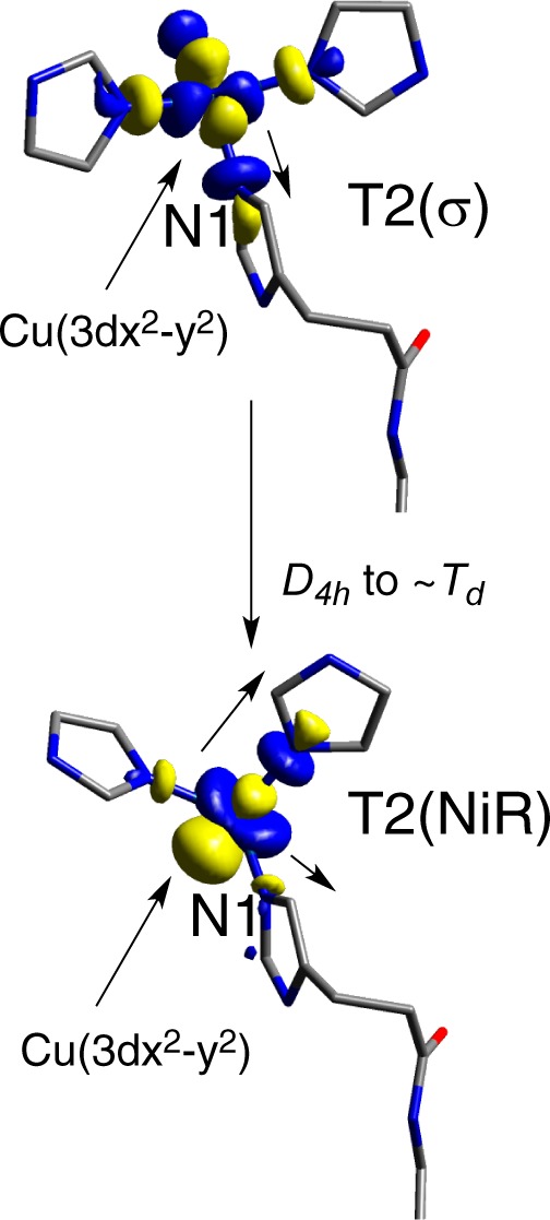
Variation between the T2(σ) (top) and T2(NiR) (bottom) models. Note that in T2(NiR) the H2O is below the plane and covered by the orbital isosurface.
Perturbing the idealized T2(σ) site to the actual structure in NiR (T2(NiR)) decreases the calculated HDA for both the blue and green T1 sites. Specifically, the blue site HDA decreases from 6.9 to 2.2 cm–1, while HDA for the green site decreases from 16.4 to 5.8 cm–1 (Table 2). This is an equivalent decrease in HDA by a factor of ∼3 for both blue and green sites.
The structural change involved in transforming the T2(σ) to T2(NiR) involves an ∼D2d distortion of the ligands toward tetrahedral, with rotation of the ligands around the T2 Cu–N1(His) bond (N1 labeled in Figure 11). This structural change rotates the T2 Cu(3dx2–y2) orbital, which, in T2(NiR), results in the misalignment of the lobe of the Cu(3dx2–y2) orbital and the lobe of the N1(His) ligand (Figure 11, top to bottom). This misalignment decreases the covalency of the Cu–N1(His) bond from 7.2 to 1.9%N(σ) (MPA) or from 9.5 to 1.8%N(σ) (CSPA) (Supporting Information, Table S3). Note that the coefficients on the relevant P1 and P2 atoms do not change (Supporting Information, Table S7). Given the findings of the above sections, this decrease in covalency of the T2 Cu(II)–N(His) bond also decreases HDA. Given that the T2(NiR) site is common to both blue and green models, the decrease in HDA is similar and ∼3 in both.
3.2.2. Multicopper Oxidases
The MCOs also use a Cys-His pathway for intramolecular ET, which connects the T1 Cu site to the T3b Cu of a catalytic trinuclear Cu cluster, where O2 is reduced to H2O. We note that there are also two other potential ET pathways to the T3a and T2 site of the trinuclear Cu cluster in the MCOs. The presence of multiple pathways to multiple Cu sites in the MCOs can result in constructive or destructive interference. These additional pathways are not included here, but will be the subject of a future study. This section is therefore limited to a comparison between P1 and P2 of the Cys-His bridge in NiRs and MCOs. Through this comparison we find a conserved variation in the Cys-His pathway structure due to different second-sphere interactions in these two classes of enzymes. It is shown below that, in going from the NiRs to MCOs, this difference activates HDA for blue sites and deactivates green T1 sites.
Comparing X-ray crystal structures of NiRs and MCOs shows a conserved difference between the protein residues in the vicinity of the Cys-His pathway. An overlay of NiR and MCO structures is given in Figure 12 (NiRs, green, and MCOs, teal). In the above sections, for NiR, both P1 and P2 of the Cys-His pathway were considered, where P2 is composed of an H-bond between the Cys carbonyl oxygen and His135 (labeled P2 H-bond(A) in Figure 12, inset, green dotted line). There is an additional second-sphere H-bond to the Cys-His pathway. For the NiRs, this H-bond(B) is formed by the C=O group of an amide from an Asn R group (red Asn and red dotted lines in Figure 12). Asn is a conserved residue across most NiRs. In the MCOs, however, this H-bond(B) is formed by the carbonyl oxygen of the protein backbone of a Pro residue, which is conserved across the majority of MCOs (black Pro and black dotted lines in Figure 12).57 The difference between the Asn and Pro H-bond(B) orientations results in a rotation of the S(Cys) Cβ–Cα–C–O dihedral angle (starred atoms in Figure 12 inset) from ∼87° for A.c. NiR (PDB ID: 1NIA44) to ∼75° for the MCO Trametes versicolor (T.v.) laccase (PDB ID: 1GYC(58)), a difference of ∼12°. This trend holds over many proteins in each class (Supporting Information Figure S6, tabulated in Supporting Information Table S8), with the average value of the dihedral angles being ∼77° for the MCOs and ∼88° for the NiRs.
Figure 12.
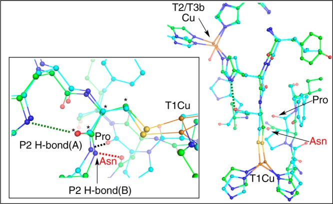
Structural overlays of NiRs and MCOs. Inset: H-bonds to the Cys-His pathway (green, NiR, PDB ID: 1NIA; and teal, MCO, PDB ID: 1GYC). The S(Met) ligand has been removed from the NiR structure for clarity.
To make a direct comparison to the calculations in section 3.2.1, the dihedral angle in both the P–P1–P2–B and P–P1–P2–G T2(NiR) models was rotated from ∼87° to ∼75°. This increases HDA for the blue site from 2.2 to 5.5 cm–1 and decreases HDA for the green site from 5.8 to 0.4 cm–1 (Table 2) (see Supporting Information, Figure S7, for structures), thus favoring a higher HDA for the blue π T1 site over the green σ T1 site. Since the MCOs contain strictly blue sites and the NiRs operate with both green and blue sites, determining the molecular orbital origin of this variation in HDA for blue vs green sites is of interest.
Comparing the β-LUMOs indicates that the rotation of the P2 dihedral has little to no influence on the T1 or T2 Cu(II)-ligand bonds (compare columns two and three to four and five in Supporting Information Table S9). However, upon rotation of the P2 dihedral, the O(p)-character decreases for the green site (Figure 13A, arrows), while the O(p)-character increases for the blue site (Figure 13B, arrows; Supporting Information Table S10, bolded; compare to bolded in Supporting Information Table S7: blue site, ∼0.00 → 0.03%; green site, ∼0.04 → 0.01%)). Thus, rotation of the P2 S(Cys) Cβ–Cα–C–O dihedral angle from ∼87° to ∼75°, a structural perturbation in going from NiRs to MCOs, varies the O(p)-centered character of the P2 amide differently for blue and green sites, which activates P2 superexchange for blue π T1 sites and deactivates it for green σ T1 sites while leaving P1 unperturbed.
Figure 13.
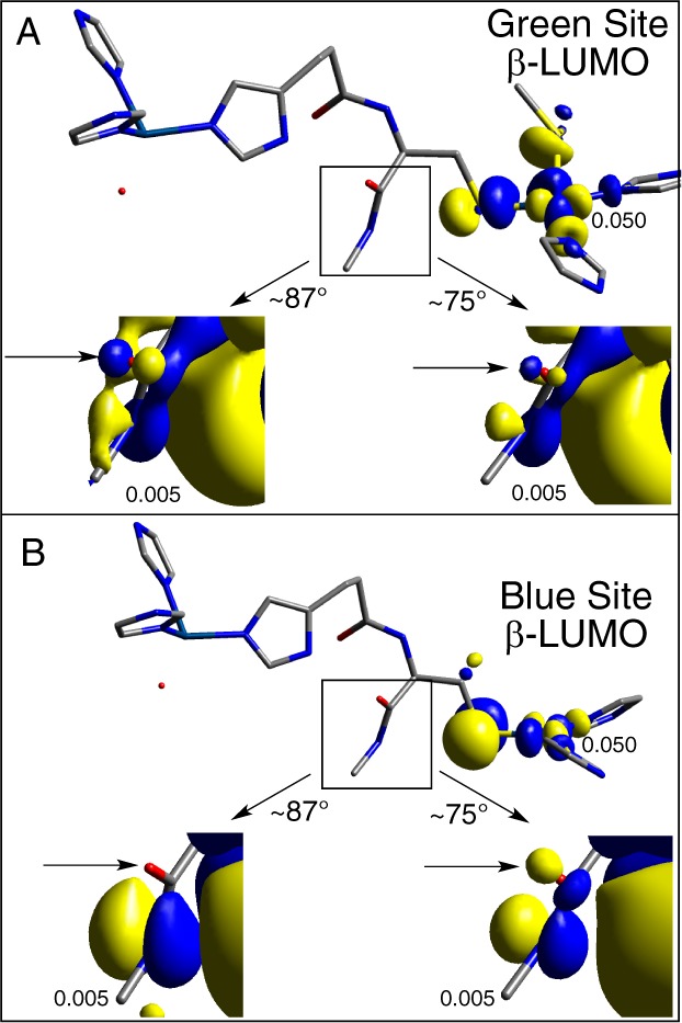
Effect of P2 rotation for the NiR-to-MCO transition in Figure 12 on the T1 green (A) and blue (B) β-LUMOs. Orbital isosurface values are given.
4. Discussion
Both the NiRs and MCOs use a similar structural motif in order to carry out catalysis: a T1 Cu ET active site is covalently linked to a remote, catalytic active site containing an additional one or three Cu ions, respectively. This Cys-His pathway provides two potential superexchange pathways (P1 and P2, Figure 2). This study has focused on the elucidation of structural and electronic factors that allow for this Cys-His pathway to operate efficiently for different T1 Cu active sites, with focus on the T1 to T2 pathway in NiRs and the analogous T1 and T3b pathways in MCOs. Importantly, the high degree of covalency of the T1 Cu–S(Cys) bond activates a hole-superexchange pathway via occupied valence orbitals of the Cys-His pathway through LMCT to the Cu(II) center. This is covalency activated superexchange.
Models containing only P1 showed that the local protein fold, which governs the structure of the Cys-His pathway, effectively activates or deactivates specific superexchange pathways for T1 Cu sites that have different electronic structures (i.e., blue π vs green σ). The idealized linear Cys-His pathway is strongly activated for a green σ site (L–P1–G, 22.7 cm–1) and deactivated for a blue π site (L–P1–B, 0–0.7 cm–1). This preference for green over blue was due to the σ/σ and π/σ nature of the T1 Cu/T2 Cu coupling, respectively. The linear, all-trans conformation of the bridge facilitates σ/σ coupling due to the high degree of mixing between the σ-bridge molecular orbitals involved in bonding at the T1 and T2 Cu sites. In the σ/π case of the blue site, however, orthogonality of the β-LUMOs precludes electronic coupling. Importantly, for the Cys-His pathway in the natural protein configuration of the NiRs, the fold overcomes the orthogonality problem by having the His R group imidazole exit at an ∼90° angle to the backbone (Figure 4D). This orientation results in a π-to-σ crossover in the overlap and allows the blue π site to couple to the T2 Cu σ site. In parallel, the ∼90° orientation of the Im-group deactivates what was an efficient superexchange pathway for the green σ site in the linear, all-trans configuration (Figure 4E; HDAP–P1–G, 1.2 cm–1).
Addition of the H-bond pathway P2 to the NiR model indicated that the blue π site and green σ site utilize different superexchange pathways of the Cys-His bridge. Specifically, the blue π site only uses P1 superexchange in NiR, while the green σ site utilizes P2 superexchange. Thus, the anisotropic covalency of the T1 Cu(II) bond activates specific superexchange pathways of the same molecular bridge, and these pathways (i.e., P1 and P2) can have different efficiencies due to the differences in the covalency, number of atoms and H-bonds, and orbital overlap interactions with the acceptor (Figure 11). Because of the higher overall efficiency of P2, the green σ site has a higher HDA (P–P1–P2–G, 16.4 cm–1) than the blue π site (P–P1–P2–B, 6.9 cm–1) in NiR, despite the lower covalency of the Cu(II)–S(Cys) bond for the green T1 center. Further, it was found that HDA is also affected by the distortion of the acceptor T2 Cu site from T2(σ) to T2(NiR) (Figure 11), which decreased the T2 ligand covalency and HDA for both blue and green T1 Cu sites. Thus, the ligand environment around both the donor and acceptor metal sites controls the superexchange pathway both in selectivity and efficiency through anisotropic covalency activated superexchange; these are tuned by the protein environment.
The second coordination sphere also plays a role in tuning the geometric structure and efficiencies of the ET pathways in the Cys-His bridge. Extension of the NiR model to the MCOs indicated that structural perturbations can lead to significantly different coupling, and thus HDA, for blue and green sites. By changing the H-bonding pattern to P2 in going from NiRs to MCOs (P2 H-bond(B) in Figure 12), the S(Cys) Cβ–Cα–C–O dihedral angle (starred atoms in Figure 12 inset) rotates from ∼87° to ∼75°. This structural change activates the P2 superexchange for the blue π site, while deactivating it for the green σ site. Thus, the second-sphere environment tunes HDA to selectively favor a T1 Cu green site in the NiRs and a T1 Cu blue site in the MCOs.
4.1. Comparison to Experiment
Kinetics data have been obtained for intramolecular ET via the Cys-His pathway in the NiRs. Rates and driving forces have been measured for different blue and green T1-containing enzymes as well as axial ligand variants within the same green NiR, thus enabling the calculations above to be compared to experiment.30−32,60 Relevant ET parameters are summarized in Table 3. Note that because of the additional ET pathways and Cu acceptors in the MCOs, the scope of this section is limited to the NiRs. For blue NiR sites, the forward rates (kf) are ∼280 s–1 and ΔG0 is small (Table 3). In one case, the blue Cu NIR ET rate and driving force, in combination with an estimate of HDA (determined for a Ru-modified high-potential iron–sulfur protein (HiPIP) containing a Cys-His pathway61) were used to obtain a λT of ∼1.2 ± 0.1 eV for intramolecular ET between blue T1 and T2 Cu.32 However, from the results presented above, HDA for the Cys-His pathway is strongly dependent on the bridge conformation and the nature of the redox active orbitals of the donor and acceptor metal sites. Alternatively, HDA can be estimated given kf, ΔG0, and a reasonable value of λT. λT for blue copper sites have be determined experimentally to be ∼0.77 eV (i.e., Pc, 0.72 eV62, and Az, 0.82 eV63). From computational studies on reduced and oxidized structures, the inner-sphere reorganization energy for a blue Cu T1 site (with or without a weak axial Met ligand) is ∼0.40 eV, giving an outer-sphere contribution of ∼0.40 eV. λi of the T2 Cu site is estimated here to be 1.50 eV.59 Using λo ≈ 0.40 eV for the T2 site, the λT for blue T1 to T2 intramolecular ET is estimated to be ∼1.34 eV. Using this value of λT for blue NiRs, we estimate HDA ≈ 1.0 ± 0.2 cm–1 (Table 3). The DFT calculated value of 2.2 cm–1 therefore overestimates HDA by a factor of ∼2.
Table 3. Experimental Rates and Driving Forces, and Calculated Reorganization Energies and HDA Values, for ET between T1/T2 Sites in Different NiRs and NiR Axial Ligand Variants.
| enzyme | kf (298 K) | ΔG0 (eV) | λTc | HDA (cm–1)d | ref |
|---|---|---|---|---|---|
| Axn (blue) | 185 | 0.009 | 1.34 | ∼0.7 | (30, 60) |
| Axg (blue)a | 290 | 0.040 | 1.34 | ∼1.1 | (33) |
| Axn (blue)a | 360 | 0.035 | 1.34 | ∼1.2 | (33) |
| Ac (green)a | 1100 | –0.035 | 1.38 | ∼1.3 | (33) |
| Ac (green) | 335 | 0.019 | 1.38 | ∼1.2 | (30, 60) |
| Af (green) | 1696 ± 73 | –0.020 | 1.38 | ∼1.9 | (31) |
| Af M150G (blue) | 18 ± 4 | 0.077 | 1.34 | ∼0.4 | (31) |
| Af M150Tb (blue) | 11 ± 4 | 0.106 | 1.34 | ∼0.8 | (31) |
| Af M150H (green) | 2333 ± 163 | –0.126 | 1.58 | ∼2.3 | (31) |
T not reported, 298 K used here.
T = 275 K.
Values estimated in this work as outlined in the text.
Values calculated in this work using the Marcus expression and the values of kf, ΔG0, and λT given in the table.
In going from blue to green NiRs, the kfs increase across different species, while ΔG0 is somewhat variable, but low (Table 3). The increased rates for green enzymes have previously been ascribed to lower reorganization energies for the green T1 Cu site relative to a blue site, as it was assumed HDA would be the same for the Cys-His pathway in both classes of NiRs.31,60 However, literature consensus is that the T1 Cu inner-sphere reorganization energies for green sites are higher than blue sites by at least ∼70 mV.64,65 λT for the intramolecular ET of green NiRs can therefore be estimated as ∼1.38 eV. Using this λT results in HDA values for green sites that are higher than those for blue sites by a factor of ∼1.6 (Table 3, ∼1.6 ± 0.3 cm–1). This ratio of the HDA for green relative to blue NiRs (∼1.6) is in reasonable agreement with the ratio from the calculations presented above (∼2.5). It is noted that values for HDA have been calculated with 38% HF mixing to agree with the experimental value for the covalency of a blue Cu site. As confirmed in this study, HDA is dependent on this covalency, and varying the amount of HF exchange changes the covalency of the Cu–S(Cys) bond, which indeed is found to increase the calculated HDA (see Supporting Information, Figure S8 and supporting text).
Rates and driving forces have also been measured for axial ligand variants within the same green T1 NiR. These allow for an estimate of the dependence of HDA with variation of the T1 Cu geometric and electronic structure within the same enzyme. From the absorption data,66,67 eliminating the strong Cu–S(Met) axial interaction from the green T1 site results in conversion to a blue site (e.g., for M150G and M150T). These axial ligand variations result in different rates and driving forces. Corrected for driving force, the significant decreases in the rates observed for the variant blue NiRs have also been interpreted as resulting from increases in inner-sphere reorganization energy of the T1 sites. However, from the considerations above, λT for the blue relative to the green site should decrease. Taking this into account, the decreased rates for the blue axial variants are consistent with decreased HDA values by a factor of ∼3 relative to the WT green NiR (Table 3). Lastly, exchanging the S(Met) axial ligand with N(His) results in increased Sp(σ) character of the T1 site as observed in absorption66 and an increased rate of intramolecular ET (Table 3). The rate increase is partially due to the increased driving force; however, HDA for this variant can be estimated using a reasonable value of λi (calculated to be ∼0.48 eV higher than for a green T1 site with a S(Met) ligand). λT and HDA can be estimated to be ∼1.58 eV and ∼2.3 cm–1, respectively, for the M150H green variant.
In NiRs, the experimental ET rate correlations between blue and green enzymes and variants are consistent with the above computational results, which indicate that HDA through the same Cys-His pathway can be varied through the anisotropic covalency of the donor (and acceptor) metal site.
4.2. Correlation of Ground-State Exchange Coupling to HDA
Previously, a valence bond configuration interaction (VBCI) model was used to relate the ground-state exchange coupling constant, J, for a homovalent dimer (i.e., Cu(II)–Cu(II)) to the HDA for Cu(I) → Cu(II) ET.53,54 The idea here is that these involve the same superexchange pathways and should correlate. Specifically, J was related to HDA by53,54
| 2 |
where U is the Mott–Hubbard parameter for the repulsion of two electrons in the same d orbital. This has been estimated to be ∼6.5 eV for Cu(II) compounds using variable energy photoelectron spectroscopy.68HDA in eq 2 is for a homovalent dimer, and for biological ET, HDA for the mixed-valent dimer (HDA(MV)) is given by53,54
| 3 |
where the factor of 1/2 derives from the loss of two-fold symmetry of the dimer due to the additional electron. In this computational study, we obtained HDA using the T1Cu(II)/T2Cu(II) triplet ground state. Computationally, we can calculate J for the same system from the triplet and the MS = 0 spin-polarized singlet states using the broken-symmetry formalism (methodology section). Using eqs 2 and 3, an HDA can be estimated from this J and compared to the value for HDA calculated above. This comparison is made using the linearized L–P1–G model from section 3.1.1 as it simply reflects a single σ/σ superexchange pathway. −2J is calculated to be 0.066 cm–1, which gives (eqs 2 and 3) an HDA(MV) = 29.5 cm–1. This compares well to the 22.7 cm–1 value of HDA calculated in section 3.1.1 by bringing the β-LUMOs of the 2Cu(II) dimer into and out of resonance.
While these values are larger than the experimental estimate of ∼1.6 cm–1 for HDA in NiR, as they reflect an idealized linear Cys-His structure, the internal consistency is satisfying and supports the idea of experimentally estimating HDA for ET from −2J. The latter can be obtained by experimental methods using the isotropic component of the spin–spin coupling. Note that these values of HDA and J are obtained with 38% HF mixing, and the amount of HF mixing can affect both the covalent contribution to HDA and the electron repulsion expressed in U. The dependence of HDA and J on HF is given in the Supporting Information, Table S11.
Therefore, given a kET and the relative redox potentials of the two Cu centers (ΔG0) involved in intramolecular ET, HDA can be evaluated experimentally through J, which further allows for a reasonable estimate of λT.
5. Conclusions
T1 Cu centers are connected via a Cys-His pathway to catalytic Cu-containing active sites: a mononuclear Cu T2 Cu site in the NiRs and a trinuclear Cu cluster in the MCOs. Electronic coupling (HDA) through this bridge was shown to vary linearly with the covalency of the T1 Cu(II)–S(Cys) bond, and thus HDA between the T1 Cu and T2 Cu sites is activated via ligand–metal covalency. In addition, the covalency of the acceptor T2 Cu site can modulate HDA.
The conformation of the Cys-His bridge is governed by the local protein fold that is formed by these two residues and is composed of two ET pathways, P1 and P2 (Figure 2). While the S(Cys) of the Cys-His bridge couples the T1 Cu site into the protein backbone, the imidazole R group of the His residue exits at a right angle with respect to the backbone. This structural feature activates a superexchange pathway for the blue (π) site through a π-to-σ crossover within the ET pathway and deactivates superexchange for a green (σ) site.
Addition of the H-bond ET pathway via P2 to the NiR model greatly increased HDA for the green but not for the blue T1 Cu center. The selectivity of different pathways (P1 for blue π and P2 green σ) within the same molecular bridge was shown to result from the anisotropic covalency of the T1 Cu(II)–S(Cys) bond (i.e., π vs σ). The selectivity in ET can therefore be controlled via the active-site ligand geometry. These pathways (i.e., P1 and P2) have different efficiencies due to the number of atoms, H-bonds, distances, and orbital overlaps. P2 is the more efficient pathway and results in the green σ site having a higher HDA than blue π sites in the NiRs. This is not the case for the MCOs, however. The second coordination sphere tunes the geometric structure of the Cys-His pathway, which allows for the selective activation of HDA for blue π sites and disfavors green σ sites by activating and deactivating the P2 superexchange component, respectively. HDA can therefore be varied between a T1 Cu site and a remote catalytic Cu active site through perturbations to the donor and acceptor electronic structures through their geometric structures as well as the geometric structure of the intervening intramolecular Cys-His ET bridge.
Acknowledgments
This work was supported by NSF grant CHE-1360046 and NIH grant DK31450 (E.I.S.). R.G.H. acknowledges a Gerhard Casper Stanford Graduate Fellowship and the Achievement Rewards for College Scientists Foundation (ARCS).
Supporting Information Available
Supplementary figures, tables, and text; complete ref (34); Cartesian coordinates of several models discussed in the text. This material is available free of charge via the Internet at http://pubs.acs.org.
The authors declare no competing financial interest.
Funding Statement
National Institutes of Health, United States
Supplementary Material
References
- Malkin R.; Malmstrom B. G. Adv. Enzymol. Relat. Areas Mol. Biol. 1970, 33, 177. [DOI] [PubMed] [Google Scholar]
- Adman E. T. Adv. Protein Chem. 1991, 42, 145. [DOI] [PubMed] [Google Scholar]
- Gray H. B. Chem. Soc. Rev. 1986, 15, 17. [Google Scholar]
- Holm R. H.; Kennepohl P.; Solomon E. I. Chem. Rev. 1996, 96, 2239. [DOI] [PubMed] [Google Scholar]
- Crane B. R.; Di B. A. J.; Winkler J. R.; Gray H. B. J. Am. Chem. Soc. 2001, 123, 11623. [DOI] [PubMed] [Google Scholar]
- Solomon E. I.; Szilagyi R. K.; DeBeer G. S.; Basumallick L. Chem. Rev. 2004, 104, 419. [DOI] [PubMed] [Google Scholar]
- Colman P. M.; Freeman H. C.; Guss J. M.; Murata M.; Norris V. A.; Ramshaw J. A. M.; Venkatappa M. P. Nature 1978, 272, 319. [Google Scholar]
- Guss J. M.; Freeman H. C. J. Mol. Biol. 1983, 169, 521. [DOI] [PubMed] [Google Scholar]
- Guss J. M.; Bartunik H. D.; Freeman H. C. Acta Crystallogr., Sect. B: Struct. Sci. 1992, B48, 790. [DOI] [PubMed] [Google Scholar]
- Nar H.; Messerschmidt A.; Huber R.; Van d. K. M.; Canters G. W. J. Mol. Biol. 1991, 221, 765. [DOI] [PubMed] [Google Scholar]
- Hart P. J.; Nersissian A. M.; Herrmann R. G.; Nalbandyan R. M.; Valentine J. S.; Eisenberg D. Protein Sci. 1996, 5, 2175. [DOI] [PMC free article] [PubMed] [Google Scholar]
- Germann U. A.; Muller G.; Hunziker P. E.; Lerch K. J. Biol. Chem. 1988, 263, 885. [PubMed] [Google Scholar]
- Messerschmidt A.; Huber R. Eur. J. Biochem. 1990, 187, 341. [DOI] [PubMed] [Google Scholar]
- Lowery M. D.; Solomon E. I. Inorg. Chim. Acta 1992, 198–200, 233. [Google Scholar]
- Solomon E. I. Inorg. Chem. 2006, 45, 8012. [DOI] [PubMed] [Google Scholar]
- Solomon E. I.; Hadt R. G. Coord. Chem. Rev. 2011, 255, 774. [Google Scholar]
- Gewirth A. A.; Solomon E. I. J. Am. Chem. Soc. 1988, 110, 3811. [Google Scholar]
- Penfield K. W.; Gay R. R.; Himmelwright R. S.; Eickman N. C.; Norris V. A.; Freeman H. C.; Solomon E. I. J. Am. Chem. Soc. 1981, 103, 4382. [Google Scholar]
- Shadle S. E.; Penner-Hahn J. E.; Schugar H. J.; Hedman B.; Hodgson K. O.; Solomon E. I. J. Am. Chem. Soc. 1993, 115, 767. [Google Scholar]
- LaCroix L. B.; Shadle S. E.; Wang Y.; Averill B. A.; Hedman B.; Hodgson K. O.; Solomon E. I. J. Am. Chem. Soc. 1996, 118, 7755. [Google Scholar]
- LaCroix L. B.; Randall D. W.; Nersissian A. M.; Hoitink C. W. G.; Canters G. W.; Valentine J. S.; Solomon E. I. J. Am. Chem. Soc. 1998, 120, 9621. [Google Scholar]
- Xie X.; Hadt R. G.; Pauleta S. R.; Gonzalez P. J.; Un S.; Moura I.; Solomon E. I. J. Inorg. Biochem. 2009, 103, 1307. [DOI] [PubMed] [Google Scholar]
- Ghosh S.; Xie X.; Dey A.; Sun Y.; Scholes C. P.; Solomon E. I. Proc. Natl. Acad. Sci. U.S.A. 2009, 106, 4969. [DOI] [PMC free article] [PubMed] [Google Scholar]
- George S. J.; Lowery M. D.; Solomon E. I.; Cramer S. P. J. Am. Chem. Soc. 1993, 115, 2968. [Google Scholar]
- Lowery M. D.; Guckert J. A.; Gebhard M. S.; Solomon E. I. J. Am. Chem. Soc. 1993, 115, 3012. [Google Scholar]
- Solomon E. I.; Heppner D. E.; Johnston E. M.; Ginsbach J. W.; Cirera J.; Qayyum M.; Kieber-Emmons M. T.; Kjaergaard C. H.; Hadt R. G.; Tian L. Chem. Rev. 2014, 114, 3659. [DOI] [PMC free article] [PubMed] [Google Scholar]
- Cracknell J. A.; Vincent K. A.; Armstrong F. A. Chem. Rev. 2008, 108, 2439. [DOI] [PubMed] [Google Scholar]
- Calabrese Barton S.; Gallaway J.; Atanassov P. Chem. Rev. 2004, 104, 4867. [DOI] [PubMed] [Google Scholar]
- Marcus R. A.; Sutin N. Biochim. Biophys. Acta, Rev. Bioenerg. 1985, 811, 265. [Google Scholar]
- Farver O.; Pecht I. Coord. Chem. Rev. 2011, 255, 757. [Google Scholar]
- Wijma H. J.; MacPherson I.; Farver O.; Tocheva E. I.; Pecht I.; Verbeet M. P.; Murphy M. E. P.; Canters G. W. J. Am. Chem. Soc. 2007, 129, 519. [DOI] [PubMed] [Google Scholar]
- Farver O.; Eady R. R.; Sawers G.; Prudencio M.; Pecht I. FEBS Lett. 2004, 561, 173. [DOI] [PubMed] [Google Scholar]
- Suzuki S.; Deligeer; Yamaguchi K.; Kataoka K.; Kobayashi K.; Tagawa S.; Kohzuma T.; Shidara S.; Iwasaki H. J. Biol. Inorg. Chem. 1997, 2, 265. [Google Scholar]
- Frisch M. J.; et al. Gaussian 09; Gaussian, Inc.: Wallingford, CT, 2009.
- Tenderholt A. L.QMForge, v 2.1; Stanford University: Stanford, CA, 2007; http://qmforge.sourceforge.net.
- Gorelsky S. I.; Lever A. B. P. J. Organomet. Chem. 2001, 635, 187. [Google Scholar]
- Gorelsky S. I.AOMix: Program for Molecular Orbital Analysis, Version 6.82, 2013; http://www.sg-chem.net/.
- Kieber-Emmons M. T.LUMO, Version 0.9b, 2011; http://www.kieber-emmons.com/Lumo/
- Perdew J. P. Phys. Rev. B 1986, 33, 8822. [DOI] [PubMed] [Google Scholar]
- Becke A. D. Phys. Rev. A: Gen. Phys. 1988, 38, 3098. [DOI] [PubMed] [Google Scholar]
- Becke A. D. J. Chem. Phys. 1993, 98, 5648. [Google Scholar]
- Szilagyi R. K.; Metz M.; Solomon E. I. J. Phys. Chem. A 2002, 106, 2994. [Google Scholar]
- Schaefer A.; Huber C.; Ahlrichs R. J. Chem. Phys. 1994, 100, 5829. [Google Scholar]
- Adman E. T.; Godden J. W.; Turley S. J. Biol. Chem. 1995, 270, 27458. [DOI] [PubMed] [Google Scholar]
- Paddon-Row M. N.; Jordan K. D. J. Am. Chem. Soc. 1993, 115, 2952. [Google Scholar]
- Berlin Y. A.; Hutchison G. R.; Rempala P.; Ratner M. A.; Michl J. J. Phys. Chem. A 2003, 107, 3970. [Google Scholar]
- Newton M. D. Chem. Rev. 1991, 91, 767. [Google Scholar]
- Newton M. D. Theor. Chem. Acc. 2003, 110, 307. [Google Scholar]
- Liang C.; Newton M. D. J. Phys. Chem. 1992, 96, 2855. [Google Scholar]
- Hartings M. R.; Kurnikov I. V.; Dunn A. R.; Winkler J. R.; Gray H. B.; Ratner M. A. Coord. Chem. Rev. 2010, 254, 248. [DOI] [PMC free article] [PubMed] [Google Scholar]
- Prytkova T. R.; Kurnikov I. V.; Beratan D. N. J. Phys. Chem. B 2005, 109, 1618. [DOI] [PubMed] [Google Scholar]
- Yamaguchi K.; Jensen F.; Dorigo A.; Houk K. N. Chem. Phys. Lett. 1988, 149, 537. [Google Scholar]
- Brunold T. C.; Gamelin D. R.; Solomon E. I. J. Am. Chem. Soc. 2000, 122, 8511. [Google Scholar]
- Tuczek F.; Solomon E. I. Coord. Chem. Rev. 2001, 219–221, 1075. [Google Scholar]
- DeBeer G. S.; Metz M.; Szilagyi R. K.; Wang H.; Cramer S. P.; Lu Y.; Tolman W. B.; Hedman B.; Hodgson K. O.; Solomon E. I. J. Am. Chem. Soc. 2001, 123, 5757. [DOI] [PubMed] [Google Scholar]
- Hadt R. G.; Sun N.; Marshall N. M.; Hodgson K. O.; Hedman B.; Lu Y.; Solomon E. I. J. Am. Chem. Soc. 2012, 134, 16701. [DOI] [PMC free article] [PubMed] [Google Scholar]
- This amino acid position is conserved across most NiRs and most MCOs. The residue is observed to be a Thr in various two-domain MCOs (2dMCOs), which are generally thought to be involved in the evolutionary pathways of NiRs and MCOs.
- Piontek K.; Antorini M.; Choinowski T. J. Biol. Chem. 2002, 277, 37663. [DOI] [PubMed] [Google Scholar]
- Note that this model involves an ∼tetrahedral oxidized site (3N(His) and H2O) and a trigonal reduced site with loss of a water molecule upon reduction.
- Farver O.; Eady R. R.; Pecht I. J. Phys. Chem. A 2004, 108, 9005. [Google Scholar]
- Babini E.; Bertini I.; Borsari M.; Capozzi F.; Luchinat C.; Zhang X.; Moura G. L. C.; Kurnikov I. V.; Beratan D. N.; Ponce A.; Di Bilio A. J.; Winkler J. R.; Gray H. B. J. Am. Chem. Soc. 2000, 122, 4532. [Google Scholar]
- Di Bilio A. J.; Dennison C.; Gray H. B.; Ramirez B. E.; Sykes A. G.; Winkler J. R. J. Am. Chem. Soc. 1998, 120, 7551. [Google Scholar]
- Di Bilio A. J.; Hill M. G.; Bonander N.; Karlsson B. G.; Villahermosa R. M.; Malmstroem B. G.; Winkler J. R.; Gray H. B. J. Am. Chem. Soc. 1997, 119, 9921. [Google Scholar]
- Ryde U.; Olsson M. H. M. Int. J. Quantum Chem. 2001, 81, 335. [Google Scholar]
- Olsson M. H. M.; Ryde U.; Roos B. O. Protein Sci. 1998, 7, 2659. [DOI] [PMC free article] [PubMed] [Google Scholar]
- Wijma H. J.; MacPherson I.; Alexandre M.; Diederix R. E. M.; Canters G. W.; Murphy M. E. P.; Verbeet M. P. J. Mol. Biol. 2006, 358, 1081. [DOI] [PubMed] [Google Scholar]
- Basumallick L.; Szilagyi R. K.; Zhao Y.; Shapleigh J. P.; Scholes C. P.; Solomon E. I. J. Am. Chem. Soc. 2003, 125, 14784. [DOI] [PubMed] [Google Scholar]
- Didziulis S. V.; Cohen S. L.; Gewirth A. A.; Solomon E. I. J. Am. Chem. Soc. 1988, 110, 250. [Google Scholar]
Associated Data
This section collects any data citations, data availability statements, or supplementary materials included in this article.


