Abstract
Shape-controlled synthesis of nanomaterials through a simple, continuous, and low-cost method is essential to nanomaterials research toward practical applications. Hydrodynamic focusing, with its advantages of simplicity, low-cost, and precise control over reaction conditions, has been used for nanomaterial synthesis. While most studies have focused on improving the uniformity and size control, few have addressed the potential of tuning the shape of the synthesized nanomaterials. Here we demonstrate a facile method to synthesize hybrid materials by three-dimensional hydrodynamic focusing (3D-HF). While keeping the flow rates of the reagents constant and changing only the flow rate of the buffer solution, the molar ratio of two reactants (i.e., tetrathiafulvalene (TTF) and HAuCl4) within the reaction zone varies. The synthesized TTF–Au hybrid materials possess very different and predictable morphologies. The reaction conditions at different buffer flow rates are studied through computational simulation, and the formation mechanisms of different structures are discussed. This simple one-step method to achieve continuous shape-tunable synthesis highlights the potential of 3D-HF in nanomaterials research.
Keywords: shape-controlled synthesis, 3D hydrodynamic focusing, organic−metal hybrid materials
Nanomaterials have attracted significant research interest because of their special chemical and physical properties and their wide applications in catalysis,1 imaging,2,3 photonics,4−10 nanoelectronics,11 sensors,12−15 biomaterials,16 and biomedicine.17,18 While composition, size, and shape can each dominate the intrinsic properties of nanomaterials, shape is increasingly recognized as an important parameter.1,3,19−21 Therefore, significant effort has been devoted to synthesize nanomaterials with well-controlled shapes. For example, noble metal nanostructures in the shapes of rods,22 wires,23 belts,24 cubes,25 polyhedra,26 plates,27,28 stars,29 and dendrites30,31 have been produced recently. Shape-controlled synthesis has been achieved by approaches including wet chemical methods,2 nanolithographic techniques,32 and template-based synthesis.33 Solution-based synthetic methods have been used broadly due to their simplicity. Recently, microfluidic devices amenable to automated operation have attracted increasing interest due to their ability to minimize human factors and synthesize uniform products. The laminar flow conditions in microfluidic reactors can confine the reaction zone (i.e., the region where reaction occurs) to the interface between two reagent flows.34 Therefore, reaction conditions (e.g., flow rate, ionic concentration, and molar ratio between reagents) can be finely tuned,35−38 leading to highly controllable parametrization throughout the synthesis process.
Hydrodynamic focusing has been used to focus reagents to the center of microfluidic channels. By protecting the channel wall from the precursors to avoid precipitation, the hydrodynamic focusing techniques can maintain consistent flow condition during long-term device operation; as a result, they often achieve high product uniformity. Both two-dimensional hydrodynamic focusing (2D-HF)39 and three-dimensional hydrodynamic focusing (3D-HF)36,40−44 have been used for material synthesis already. Single-layered hydrodynamic focusing devices40,44 have attracted research interests because they are fabricated using single-step standard soft lithography, and their single-layer property makes it possible for them to be scaled up for mass production through integration of many microfluidic modules.45 Previous studies mainly focused on the fluid-focusing performance and/or the uniformity of the synthesized products. However, it has been rarely discussed that the size and shape of the synthesized products can be affected by the flow conditions.
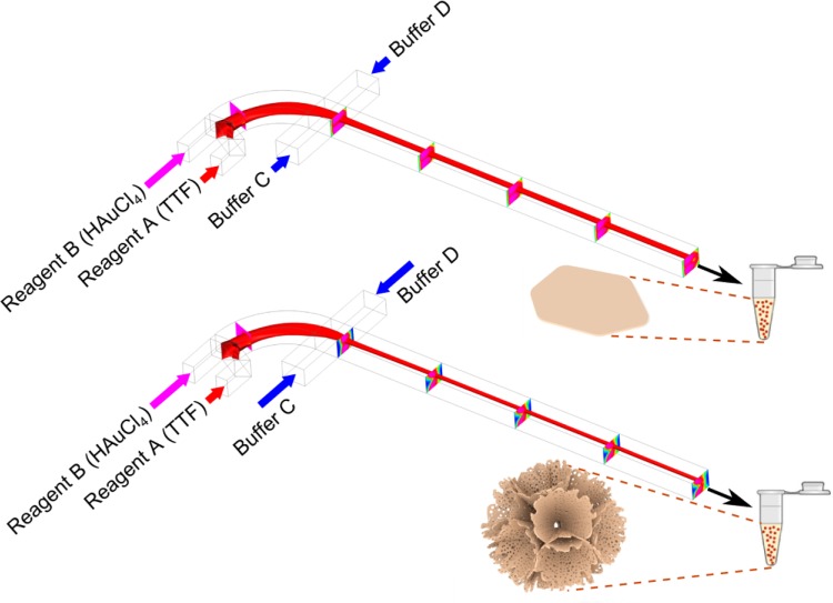
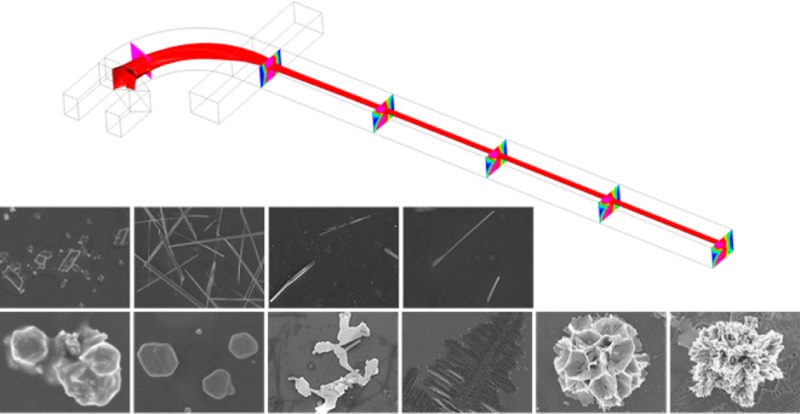
In this work, we demonstrate the chemical ratio change within the reaction zone in a “microfluidic drifting”-based 3D hydrodynamic focusing device, while the flow rate of reagents is kept the same and flow conditions are only changed via changing the buffer flow rates. By using this method, we achieve shape-controlled synthesis of tetrathiafulvalene–Au (TTF–Au) hybrid materials. Tetrathiafulvalene is an organic compound which has been used for a broad range of applications.46−50Figure 1 shows the microfluidic drifting-based 3D-HF device for the TTF–Au hybrid material synthesis. The microfluidic device consists of four inlet channels and one outlet channel. Fluid injected from inlet A is first focused vertically by the vertical sheath flow from inlet B. Then the horizontal sheath flow from inlet C and D compresses the fluid from inlet A to the center of the channel. During the experiments, reagents were injected from inlet A (reagent A) and inlet B (reagent B) at constant flow rates. Acetonitrile was injected from inlet C and D as a buffer solution at various flow rates. The products were ejected from the outlet channel into a centrifuge tube containing acetonitrile for collection. We carried out two sets of experiments: (1) TTF solution was injected from inlet A and HAuCl4 solution from inlet B, and (2) HAuCl4 solution was injected from inlet A and TTF solution from inlet B. With different buffer flow rates, the synthesized TTF–Au hybrid nanomaterials showed different morphologies, including branching aggregates, triangular or hexagonal shapes, multilayered structures, dendritic nanostructures, flower-like aggregates, coral-like aggregates, diamond shapes, and wires.
Figure 1.
Schematic demonstration of the microfluidic device for shape-controlled synthesis of hybrid nanomaterials by 3D-HF. The isocurve shows the focusing of reagent A, and the slices show the concentration distribution of reagent B. While keeping the flow rates of reagents A and B constant and changing the flow rates of buffers C and D, the concentration distribution within the microfluidic channel varies, and the synthesized products show different morphologies. For the first set of experiments, TTF solution was injected as reagent A and HAuCl4 solution as reagent B. At low buffer flow rate, the synthesized materials show hexagonal shape. As the buffer flow rate increases, flower-like aggregates can be obtained.
Results and Discussion
Preparation of TTF–Au Materials by the 3D-HF Method
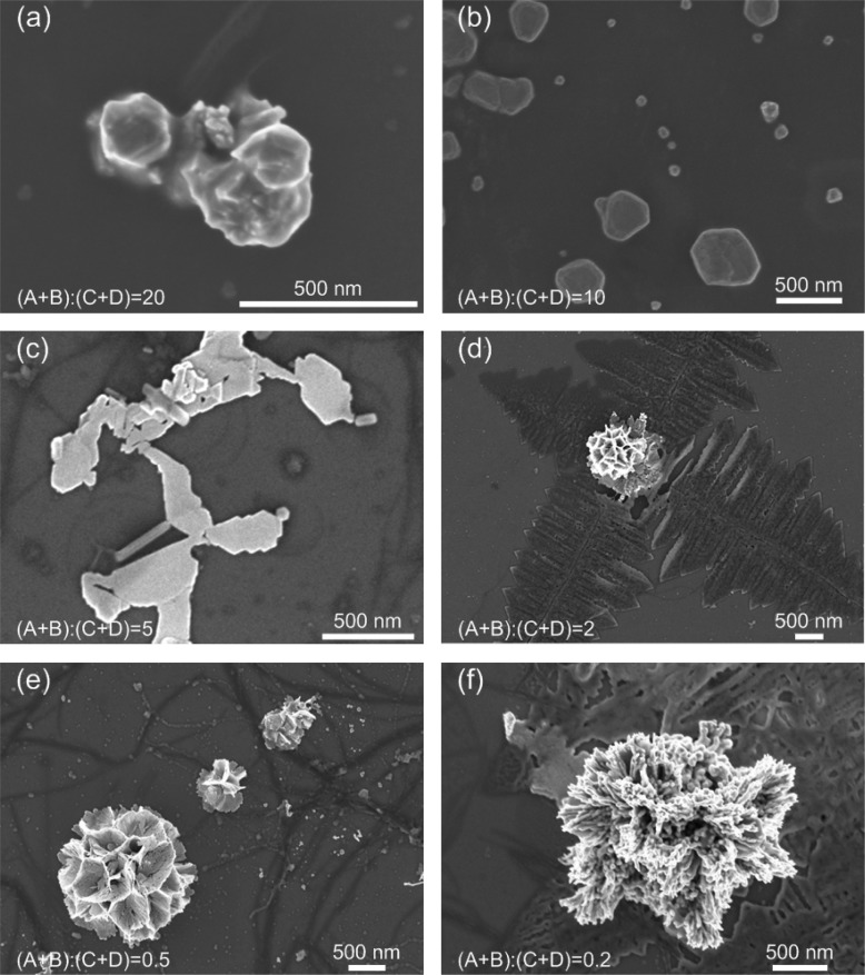
The flow rate ratio is defined as the ratio between the total flow rate from inlets A and B to the total flow rate from inlets C and D, or flow rate ratio = (A + B)/(C + D). For the first set of experiments, 1.1 mM TTF solution was injected from inlet A at 30 μL/min and 0.27 mM HAuCl4 solution from inlet B at 370 μL/min. Acetonitrile was injected from inlets C and D at various flow rates. As shown in Figure 2, as the buffer flow rate increased and the flow rate ratio decreased, the morphologies of the synthesized materials experienced changes through (a) branching aggregates consisting of irregularly aligned polyhedral crystals, (b) triangle or hexagonal shape, (c) multilayered structures consisting of thin and flat layers, (d) two-dimensional dendritic nanostructures, (e) flower-like aggregates consisting of thin, flat petals with holes, and (f) coral-like aggregates consisting of fibers (see Figures S1–S6 in Supporting Information for SEM images showing more structures).
Figure 2.
SEM images of materials prepared while using 1.1 mM TTF solution as reagent A and 0.27 mM HAuCl4 solution as reagent B. The flow rate was set to 30 μL/min for TTF solution and 370 μL/min for HAuCl4 solution, while the flow rate of buffer solution varied. As the buffer flow rate increased, flow rate ratio = (A + B)/(C + D) decreased, the morphologies of the synthesized nanomaterials experienced changes through (a) branching aggregates consisting of irregularly aligned polyhedral crystals, (b) triangle or hexagonal shape, (c) multilayered structures consisting of thin and flat layers, (d) two-dimensional dendritic nanostructures, (e) flower-like aggregates consisting of thin, flat petals, and (f) coral-like aggregates consisting of fibers.
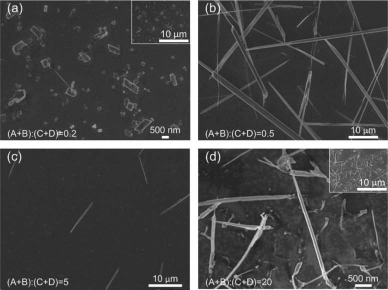
In the second set of experiments, 0.27 mM HAuCl4 solution was injected from inlet A and 1.1 mM TTF solution from inlet B at constant flow rates of 30 and 370 μL/min, respectively. As shown in Figure 3, as the buffer flow rate decreased and flow rate ratio increased, the morphologies of the synthesized materials experienced changes through (a) diamond shape with an apex angle of 58°, (b) long wires of several tens of micrometers, (c) wires of ∼10 μm, and (d) wires of 3–5 μm. In general, the products were one-dimensional structures, whose sizes first increased and then decreased with the increase of flow rate ratio. Structures with lengths comparable to the channel dimension (Figure 3b) were often formed parallel to the flow direction.51
Figure 3.
SEM images of nanomaterials prepared while using 0.27 mM HAuCl4 solution as reagent A and 1.1 mM TTF solution as reagent B. The flow rate was set to 30 μL/min for HAuCl4 solution and 370 μL/min for TTF solution, while the flow rate of the buffer solution varied. As the flow rate ratio increased, the morphologies of the synthesized nanomaterials experienced changes through (a) diamond shape with apex angle of 58°, (b) long wires of several tens of micrometers, (c) wires of ∼10 μm, and (d) wires of 3–5 μm. Insets in (a) and (d) show the structures at the same scale as that in (b) and (c) to aid comparison.
Possible Mechanism of Morphological Evolution with Change of Buffer Flow Rate
At first glance, it is surprising that variation of the buffer flow rate alone leads to significant change in the morphologies of the obtained materials. The reactions studied were considered to have reached completion due to dilution as the product solution was ejected from the outlet channel into the acetonitrile solution, so the entire reaction took place within the channel at the interface between the two reagent streams (reaction zone). As one of the reagents is focused at the center of the channel, the reaction zone is then near the outer profile of the focused reagent stream.
Changing the buffer flow rate affects both mechanical and chemical conditions within the microfluidic channel. With the increase in buffer flow rate, the shear stress present at the interfaces of the coflowing streams increases.52,53 Since shear stress is known to affect the crystallization by aligning or rotating molecules along the flow direction, increased shear stress may lead to orientation-induced structures.54 One might attribute the morphological changes in our experiments to the change in shear stress. However, as shown in Figure 2, the materials synthesized from the first set of experiments showed dendritic and aggregate features without any directionality or alignment. Also, the highest shear stress within the reaction zone is calculated to be 3.75 Pa (see shear stress calculation in Supporting Information for details), which is much lower than the shear stress (≥0.5 × 10⁵ Pa)54 used to affect the crystallization. Therefore, the changes in the mechanical conditions are not the main reason for the change in morphologies.
Changing the buffer flow rate can also affect the chemical concentration distribution within the channel. Figure 4 shows the computational fluid dynamic simulation of the concentration distribution of the reagents after the introduction of buffer flows. As described in previous work from our group,42,43 reagent A drifts laterally to the opposite side of channel due to Dean vortices caused by the high flow rate of reagent B within a curved channel, resulting in vertical focusing. Reagent A then becomes wrapped within reagent B. The introduction of the buffer solution from inlets C and D compresses the combined streams of reagents A and B horizontally and further focuses reagent A to the center of the channel. During the focusing process, the reaction occurs at the outer profile of reagent A (reaction zone). There are two effects of the change in buffer flow rate on the chemical condition within the reaction zone. First, as the buffer flow rate increases (or flow rate ratio decreases), reagent B is diluted due to diffusion at the interface between reagent B and the buffer streams. As a result, a partial amount of reagent B cannot participate in the reaction since it diffuses out of the reaction zone. However, there is only a slight variation in the amount of reagent A within the reaction zone since it is wrapped within reagent B and shares no interface with the buffer streams. Second, as the buffer flow rate increases, the outer profile of reagent B, where the concentration is lower, is “pushed” toward the reaction zone. As a result, the molar ratio of A/B increases as the buffer flow rate increases (or flow rate ratio decreases).
Figure 4.
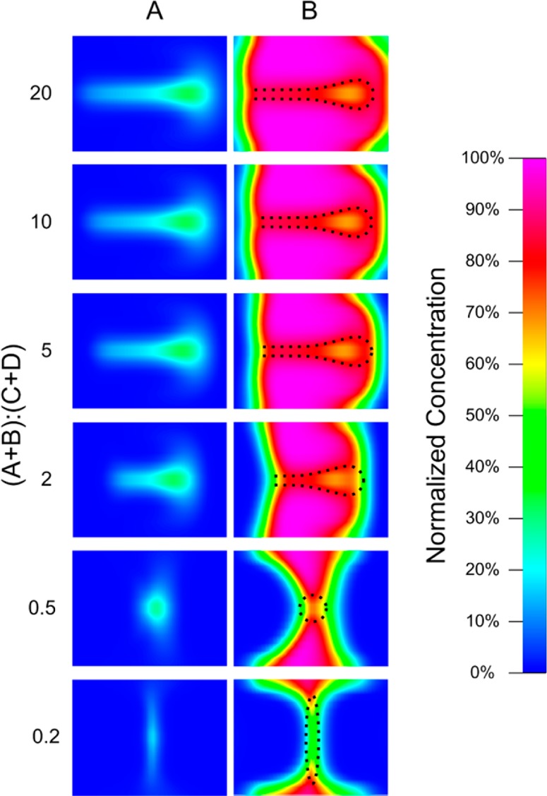
Concentration distribution of reagents A and B in the cross-sectional area after introduction of the buffer solution. The flow rates of reagents A and B were kept as 30 and 370 μL/min, respectively, and only the flow rate of the buffer solution was changed. The reaction zones (at the interface between reagents A and B) are of interest. As the buffer flow rate increased (or flow rate ratio decreased), the molar ratio of A/B within the reaction zone increased.
Therefore, the morphological evolution in the synthesized materials may be primarily due to the change in molar ratio between reagents A and B within the reaction zone. According to the experimental parameters, the products shown in Figure 2a were synthesized at the lowest molar ratio of TTF/HAuCl4, and products in Figure 3d were synthesized at the highest molar ratio.
Formation Mechanism of Different Structures
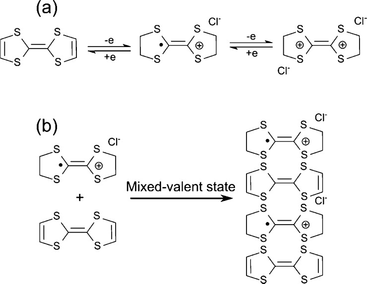
To determine the effects of molar ratio on the synthesized materials, the formation mechanism of the TTF–Au hybrid structure must be understood. TTF is a well-known electron donor unit. As shown in Figure 5a, electron-rich TTF can reversibly lose one or two electrons to form radical cation TTF+• and dication TTF2+.55−60 At the same time, this electron transfer reaction from TTF to gold cations leads to the formation of zero-valent gold (Au0).61Figure 5b shows the 1D crystallization by the interaction between radical cation TTF+• and the neutral TTF along the c-axis, which results in 1D structures.50,62,63 The reaction between TTF and HAuCl4 is sensitive to the feed molar ratio. As the feed molar ratio between TTF and HAuCl4 changes, different crystal structures can be formed (Figure S10 in the Supporting Information).
Figure 5.
Schemes illustrating (a) oxidation of TTF and (b) 1D crystallization through the interaction between the neutral and oxidized TTF.
When the molar ratio of TTF/HAuCl4 is very low, the concentration of HAuCl4 is much higher than TTF, and the major products are gold crystals. TTF acts as a capping agent by being absorbed on the (111) plane of gold crystals.61 While the (111) plane is stabilized and further growth is inhibited, the gold crystals show the (111) plane as the top surface (as indicated in Figure S10). Therefore, the products in Figure 2a–c should be gold structures. In Figure 2a, the molar ratio of TTF/HAuCl4 was so low that only very few gold cations were reduced to Au0, and the low concentration of gold resulted in small gold structures. From Figure 2a–c, the molar ratio of TTF/HAuCl4 increased and the concentration of Au0 increased, due to the capping agent effect of TTF, and the structures began to appear in thin layers, possibly with the top face of the (111) plane.
Further increase of the molar ratio of TTF/HAuCl4 resulted in structures showing features dramatically different from gold crystals, which may be caused by the interaction of gold and TTF crystallization. In this case, it became difficult to get pure structures, as evidenced in Figure 2d–f. The morphologies of two-dimensional dendritic fractal structures in Figure 2d are generally associated with non-equilibrium growth phenomena.64,65 As the particles travel through Brownian trajectories to the growing clusters, they stick to a cluster arm, and thus growth preferentially takes place at exterior sites, resulting in fractal structures. However, the “branches” of structures in Figure 2d are straight, which are different from those random fractal structures,48 indicating that the 1D crystallization of the neutral and oxidized TTF may have played a role during the formation process. In Figure 2e, flower-like aggregates consisting of thin and flat petals with holes were obtained. The formation of this type of structures may be due to fast crystallization process. The concentration of gold was high enough to cause TTF molecules to wrap within the quickly crystallized gold disk. Later in the acetonitrile, the wrapped TTF was dissolved gradually, leaving the observed holes on the disks.61 In Figure 2f, coral-like aggregates consisting of fibers were obtained, which started to show features of the 1D TTF crystallization.
Further increase in molar ratio of TTF/HAuCl4 results in TTF-based crystal structures (as indicated in Figure S10), with gold clusters acting as capping agents by bonding to the S sites of the TTF crystals through covalent Au–S bonds. The Au–S bonds inhibit the lateral or multidimensional growth of TTF crystals.66 As a result, products in Figure 3 show 1D features. From Figure 3a,b, the increase in the molar ratio resulted in higher concentrations of both neutral and oxidized TTF, leading to the increase in size. However, further increase of the molar ratio from Figure 3c,d decreased the HAuCl4 available to oxidize TTF, and the lack of oxidized TTF resulted in decreased size.
Optical Properties of the Product Solutions
The UV–vis absorption spectra of the freshly made solutions are shown in Figure 6a. All of the samples show absorption peaks at 442 and 587 nm, which are the absorption bands derived from the π–π* transition of the TTF cation radical.62,67 This absorption behavior indicates that the electron transfer reaction occurred in the solution and resulted in the formation of the radical cation TTF+•.
Figure 6.
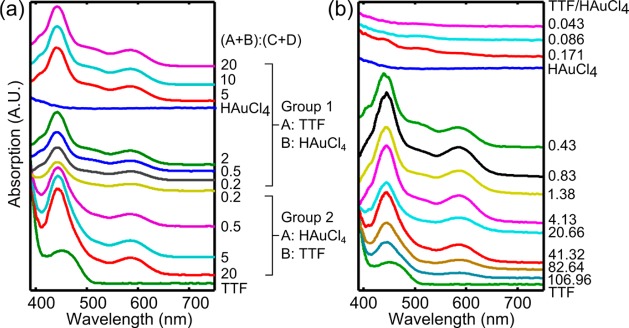
Absorption spectra of the product solutions from (a) 3D-HF and (b) bulk mixing experiments. (a) In the case of 3D-HF, two evident absorption bands derived from the π–π* transition of the TTF cation radical appear at 442 and 587 nm in all cases, indicating that the electron transfer reaction proceeded and resulted in the formation of TTF radical cations. For samples in group 1, as the flow rate ratio of (A + B)/(C + D) increases, the absorption at a wavelength around 406 and 510 nm increases. The absorption peak at 510 nm indicates the formation of gold nanoparticles. This absorption band is significantly damped because of small particle size and the organic capping by TTF. (b) In the case of bulk mixing, when the feed molar ratio is TTF/HAuCl4 ≤ 0.171, the absorption band at 510 nm increases as the feed molar ratio of TTF/HAuCl4 increases, indicating formation of more gold nanoparticles. When the feed molar ratio is TTF/HAuCl4 ≥ 0.43, the absorption band at 510 nm decreases as the TTF/HAuCl4 increases, indicating less formation of gold nanoparticles. The strong bands at 442 and 587 nm show the presence of TTF radical cations. When TTF/HAuCl4 = 0.43, the absorption band at 406 nm appears.
The top group of data corresponds to samples shown in Figure 2. When the flow rate ratio is high, the absorption peak around 510 nm is enhanced. This 510 nm peak is caused by the surface plasmon resonance absorption of gold nanoparticles, evidencing the formation of gold nanocrystals (Figure 2a–c).68 When the flow rate ratio is ≤5, the absorption at 510 nm is diminished, indicating the change of synthesized structures (Figure 2d–f). This top group of curves also shows a small absorption peak at 402 nm, which is similar to the absorption peak of the TTF radical cation dimerization, (TTF+)2.69,70
The spectra in the second group exhibit no absorption peak at 510 nm, indicating an absence of a discernible gold nanocrystal, which matches with Figure 3. The curves in this group are similar, even though the SEM images of the corresponding samples show different structures. This is because the UV–vis absorption spectra detect the product solution including chemicals within and outside the reaction zone. Since the flow rates of TTF and HAuCl4 solutions were kept as constants, the molar ratios of TTF/HAuCl4 in the product solution from this set of experiments were identical. As a result, the UV–vis absorption spectra are similar. The TTF crystalline structures show absorption in the infrared region, which is out of the detection range of the UV–vis spectra.66
Examination of the Possible Mechanism of Morphological Evolution
Above, we explained the morphological evolution with the variation of buffer flow rate by the molar ratio change within the reaction zone. If this explanation is true, similar structures should be able to be synthesized by the conventional bulk mixing method with various feed molar ratios. Also, the morphological evolution should follow the same trend as discussed above.
The bulk mixing experiments were carried out with a series of feed molar ratios of TTF/HAuCl4. As expected, structures similar to those in Figures 2 and 3 were obtained, as shown in Figures S8 and S9 in the Supporting Information. The morphological evolution of samples synthesized by the bulk mixing method also follows the previous discussion. The UV–vis absorption spectra of the bulk mixing samples are also similar to those of the 3D-HF samples, with only slight differences. As shown in Figure 6b, the UV–vis absorption spectra of bulk mixing samples can be divided into two groups. The first group of spectra is similar to that of pure HAuCl4 solutions. Within this group, as TTF/HAuCl4 increases, the absorption at 510 nm increases, indicating that more gold nanoparticles were formed. In contrast to the 3D-HF samples, no obvious peaks of the TTF cation radical (442 and 587 nm) can be observed in this group of data, due to the lack of TTF in the solutions. The second group of spectra is similar to that of pure TTF solution. When TTF/HAuCl4 equals 0.43, the absorption spectrum exhibits a peak around 402 nm, similar to the spectrum with flow rate ratio of 2 in Figure 6a, indicating that similar compounds were synthesized in these two cases. Further increase in TTF/HAuCl4 decreases the intensity of the absorption peaks at 442 and 587 nm. When TTF/HAuCl4 ≥ 82.64, the peak at 587 nm almost disappears, underlying the decreased amount of radical cation TTF+. This trend was not shown in Figure 6a, owing to the constant TTF/HAuCl4 ratio in the 3D-HF product solutions.
Overall, by changing the feed molar ratio during the bulk mixing process, structures similar to the samples synthesized by the 3D hydrodynamic focusing method can be produced. The morphologies, optical properties, and crystalline structures of the materials synthesized by the bulk mixing method agree well with the proposed mechanism of morphological evolution, indicating the molar ratio change in the reaction zone within the microfluidic device during the 3D-HF experiments. Therefore, we have demonstrated how the flow conditions can change the chemical environment within microfluidic channels. The current 3D-HF devices were only operated for a short period of time for the demonstration. In our experiments, selected samples fabricated by the 3D-HF method show better uniformity than those by the bulk mixing method and 2D-HF (Figure S11 and Table S2 in the Supporting Information). Further optimization, such as surface treatment within the microfluidic channel or redesign of channel geometry, can be applied to protect the channel wall from precursors to avoid precipitation during long-term operation.
Conclusions
We have demonstrated a facile method to synthesize TTF–Au hybrid materials by 3D-HF. While keeping the flow rate of reagents constant and changing only the buffer flow rate, the synthesized materials showed different morphologies. We proposed the working mechanism of local molar ratio variation by change in the buffer flow rate. This proposed mechanism was based on the computational simulation results and was further proved by the similar structures synthesized using the bulk mixing method. This study contributes to the implementation and understanding of how 3D-HF can achieve shape-tunable synthesis of nanomaterials in a simple one-step process.
Materials and Methods
Materials
Tetrathiafulvalene (TTF) and hydrogen tetrachloroaurate (HAuCl4) were purchased from Sigma-Aldrich. The reagent solutions were prepared by dissolving TTF in acetonitrile at a concentration of 1.1 mM and HAuCl4 in acetonitrile at a concentration of 0.27 mM. All materials were used without any further treatment.
Device Preparation
The 3D-HF microfluidic channel was a single-layer polydimethylsiloxane (PDMS) microchannel fabricated using soft lithography techniques, as reported previously by our group.42,44,71−73 Briefly, the mold was patterned on a silicon wafer with a photoresist (SU8-2050). The surface of the mold was modified to render hydrophobicity by coating it with 1H,1H,2H,2H-perfluorooctyltrichlorosilane (Sigma-Aldrich). The PDMS mixture was prepared by mixing the base and curing agent (Sylgard 184 silicone elastomer from Dow Corning) at the weight ratio of 10:1 and then poured onto the mold, degassed in a vacuum chamber, and later cured at 65 °C for 30 min. Subsequently, the half-baked PDMS channel was removed from the mold. The inlets and outlets were drilled with a Harris Uni-Core puncher. The channel was treated with oxygen plasma and bonded to a micro-cover-glass slide. Then, the whole microfluidic channel was cured at 65 °C overnight. The microfluidic chip was connected to syringes via tubing, and the flow rate was controlled by the neMESYS syringe pump system (Cetoni GmbH).
Preparation of TTF–Au Materials by the 3D-HF Method
In the first set of experiments, TTF solution was injected from inlet A and HAuCl4 solution from inlet B at flow rates of 30 and 370 μL/min, respectively, as demonstrated in Figure 1. Acetonitrile was injected from inlets C and D as buffer solutions. In the second set of experiments, HAuCl4 solution was injected from inlet A and TTF solution from inlet B at flow rates of 30 and 370 μL/min, respectively. The product solution was ejected from the outlet into a centrifuge tube containing 1 mL of acetonitrile until the total volume reached 1.3 mL. The optical property of the product solution was measured immediately after collection. The samples were collected by centrifugation and dispensed in acetonitrile. A droplet of each sample was dropped on a silicon wafer. After evaporation, the samples were observed by FESEM imaging.
Computation Fluid Dynamics (CFD) Simulation
The concentration distribution of reagents was simulated at different flow rates using a commercial CFD simulation software (CFD-ACE+, ESI-CFD). The simulation did not consider the reaction between TTF and HAuCl4.
Preparation of TTF–Au Materials by the Bulk Mixing Method
TTF solution at 1.1 mM and HAuCl4 solution at 0.27 mM were mixed in a 1.5 mL Eppendorf centrifuge tube at different molar ratios, while keeping the total volume at 0.5 mL. Vortexing was performed for 60 s to fully mix the solution. The optical properties of the product solution were measured immediately after vortexing. A droplet of the product solution of each sample was dropped on a silicon wafer. After evaporation, the samples were observed by SEM imaging.
To obtain clear XRD results, a minimum of 20 mL of the product solution is required for each sample. Multiple preparations were carried out to collect enough sample volume. Each time, TTF solution at 1.1 mM and HAuCl4 solution at 0.27 mM were mixed at different molar ratios in a 1.5 mL Eppendorf centrifuge tube, while keeping the total volume at 1.5 mL. A 1 cm × 1 cm silicon substrate was placed in a 50 mm diameter Petri dish containing 20 mL of product solution of each sample. After evaporation, powder formed on the silicon wafer with a thickness suitable for XRD characterization.
Acknowledgments
The authors thank Dr. B.K. Juluri and Dr. Q. Hao for help with experiments and discussion. This research was supported by National Institutes of Health (Director’s New Innovator Award, 1DP2OD007209-01, HL109442, EB015300, and AI096305), the National Science Foundation, and the Penn State Center for Nanoscale Science (MRSEC) under Grant DMR-0820404. Y.-P.H. is grateful to the support of Danish Research Council (11-116325/FTP) and Lundbeck Foundation in Denmark (R95-A10275). C.L.G. was supported by the Whitaker International Program and the U.S. Fulbright Program. Components of this work were conducted at the Penn State node of the NSF-funded National Nanotechnology Infrastructure Network.
Supporting Information Available
(1) SEM images with large scale showing TTF–Au hybrid materials synthesized by 3D-HF methods; (2) shear stress calculation; (3) SEM images showing TTF–Au hybrid materials synthesized by the bulk mixing method; (4) XRD pattern of structures formed at different molar ratio of TTF/HAuCl4; and (5) size distribution of selected samples. This material is available free of charge via the Internet at http://pubs.acs.org.
The authors declare no competing financial interest.
Funding Statement
National Institutes of Health, United States
Supplementary Material
References
- Burda C.; Chen X.; Narayanan R.; El-Sayed M. A. Chemistry and Properties of Nanocrystals of Different Shapes. Chem. Rev. 2005, 105, 1025–1102. [DOI] [PubMed] [Google Scholar]
- Xia Y.; Xiong Y.; Lim B.; Skrabalak S. E. Shape-Controlled Synthesis of Metal Nanocrystals: Simple Chemistry Meets Complex Physics?. Angew. Chem., Int. Ed. 2009, 48, 60–103. [DOI] [PMC free article] [PubMed] [Google Scholar]
- Xia Y.; Halas N. J. Shape-Controlled Synthesis and Surface Plasmonic Properties of Metallic Nanostructures. MRS Bull. 2005, 30, 338–348. [Google Scholar]
- Zhang L.; Song Y.; Fujita T.; Zhang Y.; Chen M.; Wang T.-H. Large Enhancement of Quantum Dot Fluorescence by Highly Scalable Nanoporous Gold. Adv. Mater. 2014, 26, 1289–1294. [DOI] [PMC free article] [PubMed] [Google Scholar]
- Zhang Y.; Wang T.-H. Quantum Dot Enable Molecular Sensing and Diagnostics. Theranostics 2012, 2, 631–654. [DOI] [PMC free article] [PubMed] [Google Scholar]
- Zheng Y. B.; Kiraly B.; Weiss P. S.; Huang T. J. Molecular Plasmonics for Biology and Nanomedicine. Nanomedicine 2012, 7, 751–770. [DOI] [PMC free article] [PubMed] [Google Scholar]
- Zhao Y.; Lin S. S.-C.; Nawaz A. A.; Kiraly B.; Hao Q.; Liu Y.; Huang T. J. Beam Bending via Plasmonic Lenses. Opt. Express 2010, 18, 23458–23465. [DOI] [PubMed] [Google Scholar]
- Zheng Y. B.; Juluri B. K.; Jensen L. L.; Ahmed D.; Lu M.; Jensen L.; Huang T. J. Dynamically Tuning Plasmon–Exciton Coupling in Arrays of Nanodisk-J-Aggregate Complexes. Adv. Mater. 2010, 22, 3603–3607. [DOI] [PubMed] [Google Scholar]
- Zhao C.; Liu Y.; Zhao Y.; Fang N.; Huang T. J. A Reconfigurable Plasmonfluidic Lens. Nat. Commun. 2013, 4, 2305. [DOI] [PMC free article] [PubMed] [Google Scholar]
- Lu M.; Juluri B. K.; Zhao Y.; Liu Y. J.; Bunning T. J.; Huang T. J. Single-Step Holographic Fabrication of Large-Area Periodically Corrugated Metal Films. J. Appl. Phys. 2012, 112, 113101. [DOI] [PMC free article] [PubMed] [Google Scholar]
- Kimura G.; Yamada K. Electrochromism of Poly(3,4-ethylenedioxythiophene) Films on Au Nano-Brush Electrode. Synth. Met. 2009, 159, 914–918. [Google Scholar]
- Shevchenko Y.; Camci-Unal G.; Cuttica D. F.; Dokmeci M. R.; Albert J.; Khademhoseini A. Surface Plasmon Resonance Fiber Sensor for Real-Time and Label-Free Monitoring of Cellular Behavior. Biosens. Bioelectron. 2014, 56, 359–367. [DOI] [PMC free article] [PubMed] [Google Scholar]
- Oh B.-R.; Huang N.-T.; Chen W.; Seo J. H.; Chen P.; Cornell T. T.; Shanley T. P.; Fu J.; Kurabayashi K. Integrated Nanoplasmonic Sensing for Cellular Functional Immunoanalysis Using Human Blood. ACS Nano 2014, 8, 2667–2767. [DOI] [PMC free article] [PubMed] [Google Scholar]
- Quan Q.; Burgess I. B.; Tang S. K. Y.; Floyd D. L.; Loncar M. High-Q, Low Index-Contrast Polymeric Photonic Crystal Nanobeam Cavities. Opt. Express 2011, 19, 22191–22197. [DOI] [PubMed] [Google Scholar]
- Quan Q.; Floyd D. L.; Burgess I. B.; Deotare P. B.; Frank I. W.; Tang S. K. Y.; Ilic R.; Loncar M. Single Particle Detection in CMOS Compatible Photonic Crystal Nanobeam Cavities. Opt. Express 2013, 21, 32225–32233. [DOI] [PubMed] [Google Scholar]
- Shao Y.; Fu J. Integrated Micro/Nanoengineered Functional Biomaterials for Cell Mechanics and Mechanobiology: A Materials Perspective. Adv. Mater. 2014, 26, 1494–1533. [DOI] [PMC free article] [PubMed] [Google Scholar]
- Chow E. K.; Zhang X.-Q.; Chen M.; Lam R.; Robinson E.; Huang H.; Schaffer D.; Osawa E.; Goga A.; Ho D. Nanodiamond Therapeutic Delivery Agents Mediate Enhanced Chemoresistant Tumor Treatment. Sci. Transl. Med. 2011, 3, 73ra21. [DOI] [PubMed] [Google Scholar]
- Mochalin V. N.; Shenderova O.; Ho D.; Gogotsi Y. The Properties and Applications of Nanodiamonds. Nat. Nanotechnol. 2012, 7, 11–23. [DOI] [PubMed] [Google Scholar]
- Mann S. The Chemistry of Form. Angew. Chem., Int. Ed. 2000, 39, 3392–3406. [PubMed] [Google Scholar]
- Sun Y.; Xia Y. Shape-Controlled Synthesis of Gold and Silver Nanoparticles. Science 2002, 298, 2176–2179. [DOI] [PubMed] [Google Scholar]
- Yang S.; Guo F.; Kiraly B.; Mao X.; Lu M.; Huang T. J. Microfluidic Synthesis of Multifunctional Janus Particles for Biomedical Applications. Lab Chip 2012, 12, 2097–2102. [DOI] [PMC free article] [PubMed] [Google Scholar]
- Jana N. R.; Gearheart L.; Murphy C. J. Wet Chemical Synthesis of Silver Nanorods and Nanowires of Controllable Aspect Ratio. Chem. Commun. 2001, 617–618. [Google Scholar]
- Sun Y.; Xia Y. Large-Scale Synthesis of Uniform Silver Nanowires through a Soft, Self-Seeding, Polyol Process. Adv. Mater. 2002, 14, 833–837. [Google Scholar]
- Zhao N.; Wei Y.; Sun N.; Chen Q.; Bai J.; Zhou L.; Qin Y.; Li M.; Qi L. Controlled Synthesis of Gold Nanobelts and Nanocombs in Aqueous Mixed Surfactant Solutions. Langmuir 2008, 24, 991–998. [DOI] [PubMed] [Google Scholar]
- Wu H.-L.; Kuo C.-H.; Huang M. H. Seed-Mediated Synthesis of Gold Nanocrystals with Systematic Shape Evolution from Cubic to Trisoctahedral and Rhombic Dodecahedral Structures. Langmuir 2010, 26, 12307–12313. [DOI] [PubMed] [Google Scholar]
- Lee J.-H.; Kamada K.; Enomoto N.; Hojo J. Morphology-Selective Synthesis of Polyhedral Gold Nanoparticles: What Factors Control the Size and Morphology of Gold Nanoparticles in a Wet-Chemical Process. J. Colloid Interface Sci. 2007, 316, 887–892. [DOI] [PubMed] [Google Scholar]
- Hao E.; Kelly K. L.; Hupp J. T.; Schatz G. C. Synthesis of Silver Nanodisks Using Polystyrene Mesospheres as Templates. J. Am. Chem. Soc. 2002, 124, 15182–15183. [DOI] [PubMed] [Google Scholar]
- Chen S.; Fan Z.; Carroll D. L. Silver Nanodisks: Synthesis, Characterization, and Self-Assembly. J. Phys. Chem. B 2002, 106, 10777–10781. [Google Scholar]
- Kumar P. S.; Pastoriza-Santos I.; Rodríguez-González B.; de Abajo F. J. G.; Liz-Marzán L. M. High-Yield Synthesis and Optical Response of Gold Nanostars. Nanotechnology 2008, 19, 015606. [DOI] [PubMed] [Google Scholar]
- Fang J.; Ma X.; Cai H.; Song X.; Ding B. Nanoparticle-Aggregated 3D Monocrystalline Gold Dendritic Nanostructures. Nanotechnology 2006, 17, 5841. [Google Scholar]
- Xiao J. P.; Xie Y.; Tang R.; Chen M.; Tian X. B. Novel Ultrasonically Assisted Templated Synthesis of Palladium and Silver Dendritic Nanostructures. Adv. Mater. 2001, 13, 1887–1891. [Google Scholar]
- Gomar-Nadal E.; Puigmarti-Luis J.; Amabilino D. B. Assembly of Functional Molecular Nanostructures on Surfaces. Chem. Soc. Rev. 2008, 37, 490–504. [DOI] [PubMed] [Google Scholar]
- Xia Y.; Yang P.; Sun Y.; Wu Y.; Mayers B.; Gates B.; Yin Y.; Kim F.; Yan H. One-Dimensional Nanostructures: Synthesis, Characterization, and Applications. Adv. Mater. 2003, 15, 353–389. [Google Scholar]
- Salmon J.-B.; Dubrocq C.; Tabeling P.; Charier S.; Alcor D.; Jullien L.; Ferrage F. An Approach To Extract Rate Constants from Reaction–Diffusion Dynamics in a Microchannel. Anal. Chem. 2005, 77, 3417–3424. [DOI] [PubMed] [Google Scholar]
- Selimović S.; Sim W. Y.; Kim S. B.; Jang Y. H.; Lee W. G.; Khabiry M.; Bae H.; Jambovane S.; Hong J. W.; Khademhoseini A. Generating Nonlinear Concentration Gradients in Microfluidic Devices for Cell Studies. Anal. Chem. 2011, 83, 2020–2028. [DOI] [PMC free article] [PubMed] [Google Scholar]
- Lim J.-M.; Betrand N.; Valencia P. M.; Rhee M.; Langer R.; Jon S.; Farokhzard O.; Karnik R. Parallel Microfluidic Synthesis of Size-Tunable Polymeric Nanoparticles Using 3D flow Focusing towards In Vivo Study. Nanomedicine 2014, 10, 401–409. [DOI] [PMC free article] [PubMed] [Google Scholar]
- Rivet C.; Lee H.; Hirsch A.; Hamilton S.; Lu H. Micorfluidic for Medical Diagnostic and Biosensors. Chem. Eng. Sci. 2011, 66, 1490–1507. [Google Scholar]
- Zhan M.; Chingozha L.; Lu H. Enabling System Biology Approaches through Microfabricated Systems. Anal. Chem. 2013, 85, 8882–8894. [DOI] [PMC free article] [PubMed] [Google Scholar]
- Karnik R.; Gu F.; Basto P.; Cannizzaro C.; Dean L.; Kyei-Manu W.; Langer R.; Farokhzad O. C. Microfluidic Platform for Controlled Synthesis of Polymeric Nanoparticles. Nano Lett. 2008, 8, 2906–2912. [DOI] [PubMed] [Google Scholar]
- Rhee M.; Valencia P. M.; Rodriguez M. I.; Langer R.; Farokhzad O. C.; Karnik R. Synthesis of Size-Tunable Polymeric Nanoparticles Enabled by 3D Hydrodynamic Flow Focusing in Single-Layer Microchannels. Adv. Mater. 2011, 23, H79–H83. [DOI] [PMC free article] [PubMed] [Google Scholar]
- Valencia P. M.; Pridgen E. M.; Rhee M.; Langer R.; Farokhzard O.; Karnik R. Microfluidic Platform for Combinatorial Synthesis and Optimization of Targeted Nanoparticles for Cancer Therapy. ACS Nano 2013, 7, 10671–10680. [DOI] [PMC free article] [PubMed] [Google Scholar]
- Mao X.; Waldeisen J. R.; Huang T. J. “Microfluidic Drifting”—Implementing Three-Dimensional Hydrodynamic Focusing with a Single-Layer Planar Microfluidic Device. Lab Chip 2007, 7, 1260–1262. [DOI] [PubMed] [Google Scholar]
- Mao X.; Nawaz A. A.; Lin S.-C. S.; Lapsley M. I.; Zhao Y.; McCoy J. P.; El-Deiry W. S.; Huang T. J. An Integrated, Multiparametric Flow Cytometry Chip Using “Microfluidic Drifting” Based Three-Dimensional Hydrodynamic Focusing. Biomicrofluidics 2012, 6, 024113. [DOI] [PMC free article] [PubMed] [Google Scholar]
- Lu M.; Ho Y.-P.; Grigsby C. L.; Nawaz A. A.; Leong K. W.; Huang T. J. A Three-Dimensional Hydrodynamic Focusing Method for Polyplexes Synthesis. ACS Nano 2014, 8, 332–339. [DOI] [PMC free article] [PubMed] [Google Scholar]
- Vladisavljevic G. T.; Khalid N.; Neves M. A.; Kuroiwa T.; Nakajima M.; Uemura K.; Ichikawa S.; Kobayashi I. Industrial Lab-on-a-Chip: Design, Applications and Scale-up for Drug Discovery and Delivery. Adv. Drug Delivery Rev. 2013, 65, 1626–1663. [DOI] [PubMed] [Google Scholar]
- Williams J. M.; Schultz A. J.; Geiser U.; Carlson K. D.; Kini A. M.; Wang H. H.; Kwok W.-K.; Whangbo M.-H.; Schirber J. E. Organic Superconductors—New Benchmarks. Science 1991, 252, 1501–1508. [DOI] [PubMed] [Google Scholar]
- Coronado E.; Galán-Mascarós J. R.; Gómez-García C. J.; Laukhin V. Coexistence of Ferromagnetism and Metallic Conductivity in a Molecule-Based Layered Compound. Nature 2000, 408, 447–449. [DOI] [PubMed] [Google Scholar]
- Wang X.; Naka K.; Itoh H.; Park S.; Chujo Y. Synthesis of Silver Dendritic Nanostructures Protected by Tetrathiafulvalene. Chem. Commun. 2002, 1300–1301. [DOI] [PubMed] [Google Scholar]
- Wang X.; Itoh H.; Naka K.; Chujo Y. Tetrathiafulvalene-Assisted Formation of Silver Dendritic Nanostructures in Acetonitrile. Langmuir 2003, 19, 6242–6246. [Google Scholar]
- Naka K.; Ando D.; Wang X.; Chujo Y. Synthesis of Organic–Metal Hybrid Nanowires by Cooperative Self-Organization of Tetrathiafulvalene and Metallic Gold via Charge-Transfer. Langmuir 2007, 23, 3450–3454. [DOI] [PubMed] [Google Scholar]
- Puigmarti-Luis J.; Kuhn P.; Cvetkovic B. Z.; Schaffhauser D.; Ruio-Martinez M.; Imaz I.; Maspoch D.; Dittrich P. S.. Guided Assembly of Nanowires and Their Integration in Microfluidic Devices. Mater. Res. Soc. Symp. Proc. 2011, 1346, http://dx.doi.org/10.1557/opl.2011.1000. [Google Scholar]
- Wang C.-W.; Sinton D.; Moffitt M. G. Flow-Directed Block Copolymer Micelle Morphologies via Microfluidic Self-Assembly. J. Am. Chem. Soc. 2011, 133, 18853–18864. [DOI] [PubMed] [Google Scholar]
- Wang C.-W.; Sinton D.; Moffitt M. G. Morphological Control via Chemical and Shear Force in Block Copolymer Self-Assembly in the Lab-on-Chip. ACS Nano 2013, 7, 1424–1436. [DOI] [PubMed] [Google Scholar]
- Kumaraswamy G.; Kornfield J. A.; Yeh F.; Hsiao B. S. Shear-Enhanced Crystallization in Isotactic Polypropylene. 3. Evidence for a Kinetic Pathway to Nucleation. Macromolecules 2002, 35, 1762–1769. [Google Scholar]
- Yamada J.-I.; Sugimoto T.. TTF Chemistry: Fundamentals and Applications of Tetrathiafulvalene; Springer: Berlin, 2004. [Google Scholar]
- Batail P. Introduction: Molecular Conductors. Chem. Rev. 2004, 104, 4887–4890. [DOI] [PubMed] [Google Scholar]
- Williams J. M.; Ferraro J. R.; Thorn R. J.; Carlson K. D.; Geiser U.; Wang H. H.; Kini A. M.; Whangbo M. H.. Organic Superconductors; Prentice Hall: Englewood Cliffs, NJ, 1992. [Google Scholar]
- Saito G.; Yoshida Y. Development of Conductive Organic Molecular Assemblies: Organic Metals, Superconductors, and Exotic Functional Materials. Bull. Chem. Soc. Jpn. 2007, 80, 1–137. [Google Scholar]
- Hasegawa M.; Daigoku K.; Hashimoto K.; Nishikawa H.; Iyoda M. Face-to-Face Dimeric Tetrathiafulvalenes and Their Cation Radical and Dication Species as Models of Mixed Valence and π-Dimer States. Bull. Chem. Soc. Jpn. 2012, 85, 51–60. [Google Scholar]
- Pop F.; Ding J.; Daku L. M. L.; Hauser A.; Avarvari N. Tetrathiafulvalene-S-Tetrazine: Versatile Platform for Donor–Acceptor Systems and Multifunctional Ligands. RSC Adv. 2013, 3, 3218–3221. [Google Scholar]
- Yang J.; Qi L.; Zhang D.; Ma J.; Cheng H. Dextran-Controlled Crystallization of Silver Microcrystals with Novel Morphologies. Cryst. Growth Des. 2004, 4, 1371–1375. [Google Scholar]
- Torrance J. B.; Scott B. A.; Welber B.; Kaufman F. B.; Seiden P. E. Optical Properties of the Radical Cation Tetrathiafulvalenium (TTF+) in Its Mixed-Valence and Monovalence Halid Salts. Phys. Rev. B 1979, 19, 730–741. [Google Scholar]
- Iyoda M.; Hasegawa M.; Kuwatani Y.; Nishikawa H.; Fukami K.; Nagase S.; Yamamoto G. Effects of Molecular Association in the Radical-Cations of 1,8-Bis(ethylenedithiotetrathiafulvalenyl)naphthalene. Chem. Lett. 2001, 30, 1146–1147. [Google Scholar]
- Meakin P. Formation of Fractal Clusters and Networks by Irreversible Diffusion-Limited Aggregation. Phys. Rev. Lett. 1983, 51, 1119–1122. [Google Scholar]
- Witten T. A.; Sander L. M. Diffusion-Limited Aggregation, a Kinetic Critical Phenomenon. Phys. Rev. Lett. 1981, 47, 1400–1403. [Google Scholar]
- Naka K.; Ando D.; Chujo Y. Effect of Substituent Groups for Formation of Organic–Metal Hybrid Nanowires by Charge-Transfer of Tetrathiafulvalene Derivatives with Metal Ion. Synth. Met. 2009, 159, 931–934. [Google Scholar]
- Tanaka K.; Kunita T.; Ishiguro F.; Naka K.; Chujo Y. Modulation of Morphology and Conductivity of Mixed-Valence Tetrathiafulvalene Nanofibers by Coexisting Organic Acid Anions. Langmuir 2009, 25, 6929–6933. [DOI] [PubMed] [Google Scholar]
- Link S.; El-Sayed M. A. Size and Temperature Dependence of the Plasmon Absorption of Colloidal Gold Nanoparticles. J. Phys. Chem. B 1999, 103, 4212–4217. [Google Scholar]
- Craig D. P.; Walmsley S. H.. Excitons in Molecular Crystals; Benjamin: New York, 1968. [Google Scholar]
- Davydov A. S.Theory of Molecular Excitons; Plenum Press: New York, 1971. [Google Scholar]
- Nawaz A. A.; Zhang X.; Mao X.; Rufo J.; Lin S.-C. S.; Guo F.; Zhao Y.; Lapsley M.; Li P.; McCoy J. P.; Levine S. J.; Huang T. J. Sub-Micrometer-Precision, Three-Dimensional (3D) Hydrodyanmic Focusing via “Microfluidic Drifting”. Lab Chip 2014, 14, 415–423. [DOI] [PMC free article] [PubMed] [Google Scholar]
- Nawaz A. A.; Nissly R. H.; Li P.; Chen Y.; Guo F.; Li S.; Shariff Y. M.; Qureshi A. N.; Wang L.; Huang T. J. Immunological Analyses of Whole Blood via “Microfluidic Drifting” Based Flow Cytometric Chip. Ann. Biomed. Eng. 2014, 10.1007/s10439-014-1041-5. [DOI] [PubMed] [Google Scholar]
- Mao X.; Lin S.-C. S.; Dong C.; Huang T. J. Single-Layer Planar On-Chip Flow Cytometer Using Microfluidic Drifting Based Three-Dimensional (3D) Hydrodynamic Focusing. Lab Chip 2009, 9, 1583–1589. [DOI] [PubMed] [Google Scholar]
Associated Data
This section collects any data citations, data availability statements, or supplementary materials included in this article.


