Abstract
Tissue clearing and subsequent imaging of transparent organs is a powerful method to analyze fluorescently labeled cells and molecules in 3D, in intact organs. Unlike traditional histological methods, where the tissue of interest is sectioned for fluorescent imaging, 3D imaging of cleared tissue allows examination of labeled cells and molecules in the entire specimen. To this end, optically opaque tissues should be rendered transparent by matching the refractory indices throughout the tissue. Subsequently, the tissue can be imaged at once using laser-scanning microscopes to obtain a complete high-resolution 3D image of the specimen. A growing list of tissue clearing protocols including 3DISCO, CLARITY, Sca/e, ClearT2, and SeeDB provide new ways for researchers to image their tissue of interest as a whole. Among them, 3DISCO is a highly reproducible and straightforward method, which can clear different types of tissues and can be utilized with various microscopy techniques. This protocol describes this straightforward procedure and presents its various applications. It also discusses the limitations and possible difficulties and how to overcome them.
Keywords: Neuroscience, Issue 89, 3D imaging, tissue clearing, transparent tissue, intact organs, optical clearing, histology, laser scanning, light-sheet microscopy, fluorescent imaging, 3DISCO, ultramicroscope
Introduction
The histological examination of biological tissues is a fundamental approach in understanding the nature of molecules/cells in their natural context. Ideally, high-resolution imaging of the entire organ is most informative and desired. Because light has a limited penetration depth, due to scattering1, fixed organs have to be sectioned in order to perform high-resolution microscopic imaging. Hence, most of the histology studies are performed on few tissue sections representing only a small portion of the organ. In some studies, e.g., those aiming to trace out neuronal connections in the brain or spinal cord, all tissue sections from the target organs are collected and imaged for a 3D reconstruction. However, tissue sectioning and subsequent imaging of individual sections has various limitations. These include being time consuming and leading to an incomplete 3D reconstruction of the tissue, due to mechanical distortions and difficulties in the alignment of the resulting images.
Recently, clearing and imaging intact transparent organs has been developed as a significant solution to this shortcoming2,3. Upon clearing, the entire organ is rendered transparent allowing the imaging light to travel end-to-end (Figure 1) to produce high-resolution images of the unsectioned organ using a laser scanning microscope such as a multi photon or light-sheet microscope (Figure 2). Various research groups have developed new tissue clearing protocols to be able to image their tissue of interest for different purposes. These include organic solvent2-5, water6,7 and electrophoresis based8 clearing protocols. Among them, 3-dimensional imaging of solvent cleared organs or 3DISCO is a readily applicable protocol on a variety of biological samples including central nervous system (CNS) organs, immune organs and solid tumors. In addition, it can be combined with different microscopy techniques such as light sheet fluorescence microscopy (LSFM), multi photon and confocal laser scanning microscopy. 3DISCO is based on clearing with readily available and inexpensive reagents such as tetrahydrofuran (THF) and dibenzyl ether (DBE)4. The entire protocol can take as short as 3-4 hr. Thus, 3DISCO is a robust and fast technique compared to traditional histological methods that may take weeks to months to complete9.
Protocol
All animal experiments were performed in accordance with IACUC (Institutional Animal Care and Use Committee) regulations on mice ~3-5 months old. The author declares no competing financial interests.
1. Animal Perfusion and Tissue Preparation
Timing: 30-60 min per mouse + post-fixation (a few hours to overnight).
Weigh the animal and anesthetize using ketamine (80-200 mg/kg) and xylazine (7-20 mg/kg) or 2.5% avertin (0.5 ml/25 g body weight IP).
Wait a few minutes for anesthesia to take complete effect.
Pinch the toe and tail of the animal to make sure that the animal is fully anesthetized.
Perfuse the animal first at RT with 0.1 M Phosphate Buffer (PB) or 0.1 M Phosphate Buffer Saline (PBS) for 5-10 min until the blood is completely removed from the tissue.
Switch the perfusion to fixative solution: 4% PFA in 0.1 M PB (or 0.1 M PBS) and continue perfusion with 4% PFA for 30-40 min at a speed of 3 ml/min.
Dissect the organ/s of interest carefully without damaging, e.g., avoid puncturing and squeezing the tissue that is being dissected.
Remove the extra tissue surrounding the organs (connective tissue, meninges or dura matter) in a petri dish filled with PBS.
Post-fix the organs in 4% PFA for a few hr or overnight at 4 ºC. Avoid long post-fixation because PFA might quench the signal or increase the autofluorecense overtime10 especially for GFP channel (which is a lesser problem in red and far red channels).
Wash the organs 2-3x with PBS at RT just before starting the clearing procedure.
2. Tissue Clearing
Timing: 2-3 hr for small organs and 1-4 days for large organs.
Notes: The fluorescent labeling of the tissues by transgene expression, viral transfection, dye tracing or antibody labeling should be completed before clearing. All tissue clearing steps are performed at RT. The clearing solutions THF, DBE, BABB (1 part benzyl alcohol and 2 part benzyl benzoate) and dichloromethane are toxic and inhalation (conduct experiments in properly ventilated fume hood) and direct contact with skin should be avoided (use nitrile gloves).
Prepare 50% (vol/vol), 70%, and 80% THF dilutions in distilled water in separate glass bottles as follows: For 50% THF, e.g., mix 25 ml THF and 25 ml of distilled water in a glass bottle with volume of larger than 50 ml.
Mix solutions by gently shaking the bottle for a 1-2 min.
Label the glass bottle clearly.
Securely close the bottles and keep the working solutions in a dark cabinet. For the best results, do not use the same working solutions longer than 1-2 weeks. Therefore, order the clearing solutions as the smallest volume available to be able use fresh stock reagents.
Fill the glass vials (e.g., 2-3 ml) with the first clearing solution, 50% THF, and transfer the organs from PBS into glass vials to start clearing.
Securely close the glass vials with their lids and use a rotator (e.g., a wheel stirrer) for stirring.
Use aluminum foil to cover and keep the glass vials in dark. Start the rotator to stir the samples in the glass vials for the indicated time (Table 1) at a constant speed (~30 rpm).
Remove the clearing solution and add the next one in the protocol when the time in Table 1 is completed.
Collect the clearing waste into glass waste containers that are kept in a hood. Repeat previous step for each clearing solution in the protocol until the end. Use a new pasteur pipette when a new clearing solution is added (e.g., changing from THF to DBE).
At the final clearing step with BABB or DBE, the incubation times can be extended or shortened until the samples become completely transparent in visible light (or yellowish/transparent if it is a very large tissue like brain).
Keep the cleared organs in the final clearing solution at all times including the imaging steps.
3. Preparing Cleared Organs for Imaging
Timing: 5-15 min.
Note: Image the cleared organs as soon as a complete clearing is achieved. To this end, follow the next steps to prepare the samples for light-sheet microscopy (e.g., ultramicroscopy) or confocal/multi-photon microscopy imaging.
Note: Cleared organs will loose their fluorescence strength over time (particularly fluorescent proteins e.g., GFP; antibody labeling is more resistant and may even give better results with longer incubations). For imaging, various fluorescent microscopy techniques can be used as long as proper handling of the organs in the clearing solution is achieved.
- For light-sheet microscopy
- Place or mount the sample appropriately.
- Fix the cleared organ by manually turning the screw of the sample holder4.
- Dip the sample into the imaging chamber (preferably made of glass) of thelight-sheet microscope that is filled with BABB or DBE, whichever was used at the final clearing step.
- For multi photon/confocal microscopy
- Mount the sample on an imaging slide (or an imaging chamber) with the final imaging solution to be able to image with a multi photon or confocal microscopy, which typically use oil or water immersed objectives.
- Use dental cement to make a border around the tissue.
- Fill the pool with BABB or DBE just before dental cement gets fully rigid. Note: The dental cement solidifies quickly; practice a few times to get familiar with it before trying the actual samples.
- Immediately place the cleared sample in the middle of the pool and cover it with a cover glass.
- Press the cover glass until it is completely sealed by dental cement and touches at the surface of the cleared organ, which will allow reaching the maximum imaging depth by confocal/multi-photon microscopy. Notes: This ensures that no clearing solution will be spilled during the imaging. Avoid dipping the imaging lens directly into clearing solution, which can harm the lens unless it is resistant to BABB/DBE or has a protective cover.
4. Imaging Cleared Organs
Timing: 15-45 min.
Collect a z-scan covering the entire cleared tissue (if the used lens allows) at the best resolution that the microscope can deliver.
Zoom in on the regions of interest to collect higher resolution images.
5. Examination of the Data with Software Amira
Load the image series to software Amira with ResolveRT module.
Enter the correct voxel sizes in “Image Read Parameter” window and press ok.
Select the “Multi Planer View” sub-application. Then use the “Thickness” slider to choose the optimum threshold for the gray values, adjusting the 2D and 3D values.
Visualize the sample by browsing the slices in different 2D orientations and using crop-corner module in 3D view. Note: A detailed troubleshooting guide of the protocol can be found in Ertürk et al4.
Representative Results
Neurons are highly polarized cells with extremely long morphology. Their function depends on the connections that they form between each other and with other tissues. Hence, mapping the structural organization of the neurons is extremely important in order to understand how they function in health and disease. However, tracing such enormous neuronal connections throughout the entire nervous system –recently named connectomics11− still remains one of the most difficult challenges in neuroscience. To this end, both EU12 and US13 have initiated large projects to map the human brain.
While 3DISCO can be employed on various organs, it has been particularly useful to trace long neuronal connections in the spinal cord and brain. For example, using ultramicroscopy scans of large cleared spinal cord segments, the axonal connections can be followed over centimeters in the rodent spinal cord (Figure 2). In a similar way, the entire cleared mouse brain (Figure 3a) and hippocampus (Figure 3b) can be imaged to follow neuronal connections in the brain.
When confocal or multi photon microscopy is used on cleared organs, the imaging resolution can be significantly improved, especially in z-dimension. For example, multi photon imaging of cleared spinal cords from GFP-M line mice (Figure 4a) achieves a seamless image throughout the entire depth (~1.5-2 mm) of the spinal cord. Confocal microcopy on the cleared spinal cord delivers improved resolution in a similar way (Figures 4b and c). Multi photon microscopy imaging of cleared brains delivers very high-resolution images to visualize fine details of neuronal structures including dendritic spines (Figure 5). The samples for 3DISCO can be labeled in various ways including transgene expression, viral transfection, dye tracing and antibody labeling. For example, it is possible to label the entire vasculature of the brain (Figures 6a and b) and spinal cord (Figures 6c and d) using lectin conjugated fluorescent tracers4, which can be used to study the blood-brain-barrier (BBB) in health and disease.
Both microglia and astrocytes are highly implicated in the pathology of neurodegeneration including Alzheimer’s diseases and traumatic injuries14,15. Using 3DISCO, their density and distribution in the spinal cord (Figure 7) or brain can be studied.
Non-neuronal tissues can also be imaged. For example, Clara cells in the entire rodent lungs can be immunolabeled with antibodies and imaged without sectioning at a single cell level (Figure 8). Similarly, it is possible to clear and image cells e.g. alpha cells in the unsectioned pancreas tissue (Figure 9).
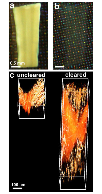 Figure 1. 3DISCO tissue clearing renders unsectioned tissues transparent for deep tissue imaging. Uncleared (a) and cleared (b) spinal cord tissues as seen by visible light. Upon clearing, deep tissue laser-scanning microscopy becomes possible. (c) Uncleared and cleared spinal cord tissues were imaged by 2-photon microscopy. Scale bars in a, b = 0.5 mm and in c = 100 µm.
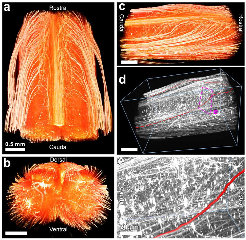 Figure 2. 3DISCO imaging of spinal cord to follow axonal extensions. The dissected spinal cord from Thy-1 GFP transgenic mouse line (GFP-M) is divided into smaller pieces (~4 mm). After following clearing protocol for small tissues (Table 1) the transparent spinal cords were visualized using ultramicroscopy. 3D reconstructions of a ~4 mm spinal cord segment in horizontal (a), coronal (b) and sagittal view (c). (d) Representative traced axons (red) are shown in the grayscale transparent view. (e) High magnification view of the indicated region in (d). Scale bars in a, b, c, d = 0.5 mm and in e = 20 µm.
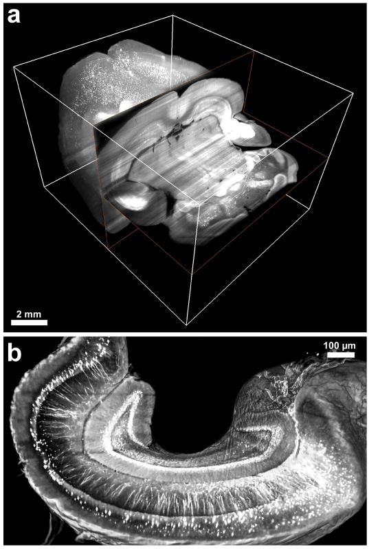 Figure 3. 3DISCO imaging of cleared brain and hippocampus. Examples of cleared brains and hippocampi of GFP-M mice were imaged with an ultramicroscope. 3D visualizations of the entire brain (a) and hippocampus (b) demonstrating the neuronal networks in the imaged transparent tissues. Scale bars in a = 2 mm and in b = 20 µm.
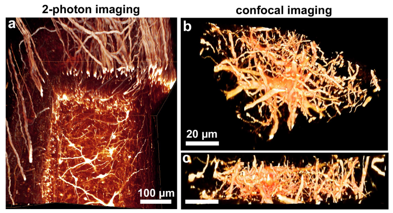 Figure 4. Tissue clearing enhances the resolution obtained by multi photon and confocal microscopy. Transparent spinal cord segments from GFP-M mice imaged by multi photon (a) or confocal microscopy (b, c). Note that clearing substantially improves the resolution and imaging depth revealing the fine structure of axons and dendrites. Scale bars in a = 100 µm and in b, c = 20 µm.
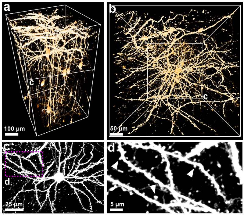 Figure 5. 3DISCO imaging of dendritic spines. Transparent brain tissue from GFP-M mice imaged by multi photon. 3D visualizations of scanned cortex region presented in vertical (a) and horizontal perspectives (b). (c) ~50 µm projection from the indicated levels in (a, b). (d) High magnification of the indicated region in (c) demonstrating the fine details of the neuronal structures including dendritic spines (arrowheads). Scale bars in a = 50 µm, in b, c = 25 µm, in d = 5 µm.
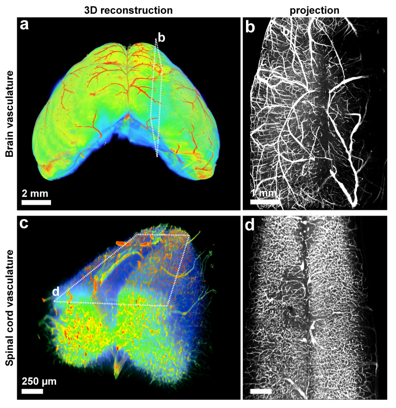 Figure 6. 3DISCO of vasculature. To label the blood vessels in the entire organs, lectin-FITC dye was used during the perfusion (before the clearing) as described16. It is noteworthy to mention that we found that tail vein injection of the tracer gives better signal over cardiac perfusion of the tracer. After collecting the fixed brains and spinal cords, they were cleared and imaged by ultramicroscopy. 3D visualization of the entire mouse brain vasculature in heatmap (a) and gray-scale (a). (b) 3D visualization of the vasculature of a mouse spinal cord segment in heatmap (c) and gray-scale (d). The heatmaps were generated based on the intensity of lectin staining; blue: low intensity (background) and red: high intensity (vasculature). Scale bars in a = 2 mm, b = 1 mm, and in c, d = 250 µm.
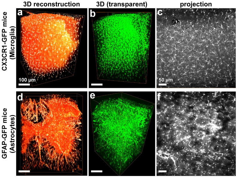 Figure 7. 3DISCO of glia cells in cleared CNS tissue. The spinal cords of transgenic mice expressing GFP in microglia TgH(CX3CR1-EGFP) or astrocytes TgN(hGFAP-ECFP) were cleared and imaged by multi photon microscopy. 3D rendering of microglia is shown as surface volume visualization (a) and transparent view (b). (c) An optical projection (~50 µm) is presented to show the details of microglia in the spinal cord. 3D rendering of astrocytes is shown as surface volume visualization (a) and transparent view (b). (f) An optical projection (~50 µm) is presented to show the details of the astrocytes in the spinal cord. Scale bars in a, b, d, e = 100 µm and in c, f = 50 µm.
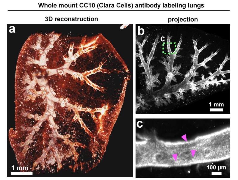 Figure 8. 3DISCO of a whole-mount lung lobe with antibody staining of clara cells. For the whole-mount antibody staining of lung lobes, 10-week-old BALB/C female mice were perfused through the right ventricle with PBS in order to remove blood from the lungs. Lungs were subsequently inflated with 4% PFA and fixed O/N at RT in fixative at least three times the volume of the tissue. Next day, the lungs were briefly rinsed in PBS and the right lobe was put in 5 ml of 1% Triton X-100 in PBS for permeabilization for 48 hr or until the tissue sank. All stainings were performed in 0.2% Triton X-100 in PBS containing 5% FBS and 2% BSA and rinses were in 0.2% Triton X-100 in PBS. Staining with anti-CC10 was for 72 hr at 4 °C followed by extensive washes for approximately 6 hr. Fluorescent labeling of the primary antibody was achieved with anti-goat-Alexa Fluor-594 secondary antibody overnight at 4 °C followed by extensive washes for 6 hr to overnight. The following day, stained lobes were cleared through 50%, 70%, and 80% THF for 30 min each followed by three 30 min washes in 100% THF, followed by 20 min in DCM, followed by 30 min in DBE. Scale bars in a and b = 1 mm and in c = 100 µm.
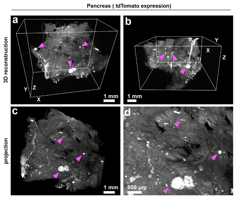 Figure 9. 3DISCO of pancreas. After perfusion of mice as described above in the protocol, the pancreas was dissected and cleared with the short protocol. The fluorescence is derived from ROSA26 LSL tdTomato recombination induced by tamoxifen treatment of mice carrying a 200 kb BAC transgene spanning the endogenous mouse glucagon locus with CreERT2 inserted into the ATG of glucagon. The arrowheads mark some of the fluorescent-labeled alpha cells in the islet. Scale bars in a, b and c = 1 mm and in d = 500 µm.
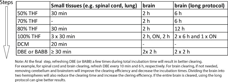 Table 1. Tissue clearing protocols for various tissues. Examples of tissue clearing protocols for different tissues. Note that the clearing time for each step can be shortened or extended as needed to improve the clearing performance. The approximate weight of small tissues is ~20-100 mg and brain is ~300-500 mg. Please click here to view a larger version of this table.
Discussion
Tissue clearing methods aim to reduce scattering of imaging light by matching the refractive indices of different tissue layers in the cleared organs. As a result, the imaging light can penetrate deep into tissues and stimulate the labeled cells/molecules. This old concept of tissue clearing17 has gained growing attention after the first sophisticated application of the technique on intact mouse brains by Dodt and colleagues2. Since then, there is a rapidly growing list of new clearing methods including 3DISCO, Sca/e, ClearT2, CLARITY and SeeDB3,4,7,18-20. In essence, they all aim to render the organs transparent for deep tissue imaging by preserving the fluorescent label. Among them, 3DISCO stands out as one of the most straightforward and reproducible methods. It is relatively fast compared to other clearing methods mentioned above (1-5 days vs. 2-3 weeks for adult brains, respectively)21. It has already been successfully applied to different organs such as the brain, spinal cord, lymph nodes, spleen, lung, solid tumors, pancreas, and mammary glands3,4,9. In addition, several publications by independent research groups already used this method to obtain imaging results22,23. Nevertheless, different tissue clearing procedures could be advantageous for different conditions. For instance, while Sca/e and SeeDB are applicable best on embryonic tissues6,7, they are water-based clearing methods, which could be easier to handle during imaging. In contrast, CLARITY is a complicated and costly clearing method. But it can be advantageous in the context of antibody labeling, especially in large tissues such as brain8.
The most critical step to obtain the best imaging results from 3DISCO is tissue labeling, which is accomplished before the tissue clearing. It is essential to start with the strongest fluorescent signal possible. This can be achieved in various ways including transgenic expression of fluorescent proteins, tracing by synthetic dyes, viral transfection or antibody labeling. It should be kept in mind that any clearing procedure will reduce the fluorescent signal of the tissues. Hence, if the fluorescent signal is not strong enough at the beginning −i.e. it is not readily detectable before the clearing− imaging of the cleared tissues will deliver poor results.
There are some limitations of clearing methods that are waiting for improvements. A critical limitation is that since clearing reagents alter the structure of the cleared organs, they cannot be used on live tissue. Hence, experiments such as with photoactivatable mEos224 should be performed before fixing and clearing. Upon clearing, super-resolution imaging of the fluorescent signal from bright and photostable proteins becomes possible. In addition, because the clearing protocol diminishes the intensity of the fluorescent proteins, the cleared organs cannot be stored for prolonged periods. It is important to note that some organs are harder to be cleared. Especially, if the dissected organs retain high amounts of blood cells (e.g., spleen, liver), they are relatively difficult to clear and image. It is also relatively harder to achieve a complete clearing for large tissues, such as adult rodent brain. Such tissues may need longer incubation times, which could, on the other hand, reduce the fluorescent signal. In addition, development of microscopy methods that can image large transparent organs at once at a high-resolution is an awaiting need to be addressed. Another important limitation of the technique is tissue labeling. While a strong fluorescent signal via genetic or virus expression is ideal, not every cell or molecule can be labeled genetically or virally. On the other hand, antibody labeling of thick tissues is not a straightforward procedure or even not possible in most cases. It may need special permeabilization protocols and long incubation times (several days to a few weeks)3. It is also important to keep in mind that the tissues shrink ~20% in each dimension (measured for spinal cord tissue) after clearing mainly due to dehydration and delipidation. This shrinkage occurs ratiometrically and should be corrected in quantification steps. As observed in the presented results, fluorescently labeled structures remain intact, which is the indication of protein integrity in the cleared tissues. Because of the hydrophobic nature of the final cleared tissue, it cannot be further stained with antibodies or embedded in water containing solutions e.g., Focusclear–which is used in CLARITY– or 80% glycerol. Finally, it is a challenge to analyze overwhelming sizes of imaging data. For example, when an entire murine brain is scanned at a cellular resolution, it would be very difficult to trace and quantify desired structures (e.g., neuronal or glia networks) and compare over different samples in an automated way. In summary, while researchers aim to find out new clearing methods, the various challenges above (difficulty of clearing diverse tissues, imaging at high resolution of larger areas, and complicated data analysis) should be improved in parallel.
In conclusion, recently developed tissue clearing techniques including 3DISCO, elegantly demonstrate that high-resolution 3D imaging of intact organs is now possible. Using these methods, scientists can obtain anatomical information of cells and molecules in the intact organ. These pioneering 3D imaging studies on transparent organs inspire a growing number of researchers to decipher complex anatomical and molecular organizations of tissues/organs in heath and disease.
Disclosures
There is nothing to disclose.
Acknowledgments
We thank C. Hojer for critical reading of the manuscript, B. Bingol (Genentech) for participation in script narrations, N. Bien-Ly for sharing the experience of improved vasculature imaging with tail vein injection of Lectin dye, and M Solloway (Genentech) for the mice used in pancreas imaging. GFP-M line was created by J. Sanes (Washington University in St. Louis) and CX3CR1-GFP mice by R. Littman (NYU). The work is supported by Genentech, Inc.
References
- Tuchin V. Tissue optics: light scattering methods and instruments for medical diagnosis. SPIE Press; 2007. [Google Scholar]
- Dodt HU, et al. Ultramicroscopy: three-dimensional visualization of neuronal networks in the whole mouse brain. Nat Methods. 2007;4:331–336. doi: 10.1038/nmeth1036. [DOI] [PubMed] [Google Scholar]
- Erturk A, et al. Three-dimensional imaging of the unsectioned adult spinal cord to assess axon regeneration and glial responses after injury. Nat Med. 2012;18:166–171. doi: 10.1038/nm.2600. [DOI] [PubMed] [Google Scholar]
- Erturk A, et al. Three-dimensional imaging of solvent-cleared organs using 3DISCO. Nat Protoc. 2012;7:1983–1995. doi: 10.1038/nprot.2012.119. [DOI] [PubMed] [Google Scholar]
- Becker K, Jahrling N, Saghafi S, Weiler R, Dodt HU. Chemical clearing and dehydration of GFP expressing mouse brains. PLoS One. 2012;7 doi: 10.1371/journal.pone.0033916. [DOI] [PMC free article] [PubMed] [Google Scholar]
- Hama H, et al. Scale: a chemical approach for fluorescence imaging and reconstruction of transparent mouse brain. Nat Neurosci. 2011;14:1481–1488. doi: 10.1038/nn.2928. [DOI] [PubMed] [Google Scholar]
- Ke MT, Fujimoto S, Imai T. SeeDB: a simple and morphology-preserving optical clearing agent for neuronal circuit reconstruction. Nat Neurosci. 2013;16:1154–1161. doi: 10.1038/nn.3447. [DOI] [PubMed] [Google Scholar]
- Chung K, et al. Structural and molecular interrogation of intact biological systems. Nature. 2013;497:332–337. doi: 10.1038/nature12107. [DOI] [PMC free article] [PubMed] [Google Scholar]
- Erturk A, Bradke F. High-resolution imaging of entire organs by 3-dimensional imaging of solvent cleared organs (3DISCO) Exp Neurol. 2013;242:57–64. doi: 10.1016/j.expneurol.2012.10.018. [DOI] [PubMed] [Google Scholar]
- Stewart JC, Villasmil ML, Frampton MW. Changes in fluorescence intensity of selected leukocyte surface markers following fixation. Cytometry Part A : the journal of the International Society for Analytical Cytology. 2007;71:379–385. doi: 10.1002/cyto.a.20392. [DOI] [PubMed] [Google Scholar]
- Lichtman JW, Sanes JR. Ome sweet ome: what can the genome tell us about the connectome. Curr Opin Neurobiol. 2008;18:346–353. doi: 10.1016/j.conb.2008.08.010. [DOI] [PMC free article] [PubMed] [Google Scholar]
- Roh MI, Chung SH, Stulting RD, Kim WC, Kim EK. Preserved peripheral corneal clarity after surgical trauma in patients with Avellino corneal dystrophy. Cornea. 2006;25:497–498. doi: 10.1097/01.ico.0000214236.59356.43. [DOI] [PubMed] [Google Scholar]
- Liu JK, Chung CH, Chang CY, Bond Shieh DB. Bond strength and debonding characteristics of a new ceramic bracket. American journal of orthodontics and dentofacial orthopedics : official publication of the American Association of Orthodontists, its constituent societies, and the American Board of Orthodontics. 2005;128:761–765. doi: 10.1016/j.ajodo.2004.03.041. [DOI] [PubMed] [Google Scholar]
- Perry VH, Nicoll JA, Holmes C. Microglia in neurodegenerative disease. Nature reviews. Neurology. 2010;6:193–201. doi: 10.1038/nrneurol.2010.17. [DOI] [PubMed] [Google Scholar]
- Maragakis NJ, Rothstein JD. Mechanisms of Disease: astrocytes in neurodegenerative disease. Nature clinical practice. Neurology. 2006;2:679–689. doi: 10.1038/ncpneuro0355. [DOI] [PubMed] [Google Scholar]
- Jahrling N, Becker K, Dodt HU. 3D-reconstruction of blood vessels by ultramicroscopy. Organogenesis. 2009;5:145–148. doi: 10.4161/org.5.4.10403. [DOI] [PMC free article] [PubMed] [Google Scholar]
- Spalteholz W. Über das Durchsichtigmachen von menschlichen und tierischen Präparaten. S. Hirzel; 1903. [Google Scholar]
- Smith C, et al. The neuroinflammatory response in humans after traumatic brain injury. Neuropathology and applied neurobiology. 2012;39:654–666. doi: 10.1111/nan.12008. [DOI] [PMC free article] [PubMed] [Google Scholar]
- Zotova E, et al. Microglial alterations in human Alzheimer's disease following Abeta42 immunization. Neuropathology and applied neurobiology. 2011;37:513–524. doi: 10.1111/j.1365-2990.2010.01156.x. [DOI] [PubMed] [Google Scholar]
- Frewin B, Chung M, Donnelly N. Bilateral cochlear implantation in Friedreich's ataxia: A case study. Cochlear implants international. 2013;14:287–290. doi: 10.1179/1754762813Y.0000000029. [DOI] [PubMed] [Google Scholar]
- Kim SY, Chung K, Deisseroth K. Light microscopy mapping of connections in the intact brain. Trends in cognitive sciences. 2013;17:596–599. doi: 10.1016/j.tics.2013.10.005. [DOI] [PubMed] [Google Scholar]
- Luo X, et al. Three-dimensional evaluation of retinal ganglion cell axon regeneration and pathfinding in whole mouse tissue after injury. Exp Neurol. 2013;247:653–662. doi: 10.1016/j.expneurol.2013.03.001. [DOI] [PMC free article] [PubMed] [Google Scholar]
- Soderblom C, et al. Perivascular fibroblasts form the fibrotic scar after contusive spinal cord injury. J Neurosci. 2013;33:13882–13887. doi: 10.1523/JNEUROSCI.2524-13.2013. [DOI] [PMC free article] [PubMed] [Google Scholar]
- McKinney SA, Murphy CS, Hazelwood KL, Davidson MW, Looger LL. A bright and photostable photoconvertible fluorescent protein. Nat Methods. 2009;6:131–133. doi: 10.1038/nmeth.1296. [DOI] [PMC free article] [PubMed] [Google Scholar]


