

Abstract
Formation of a stable cell-substrate contact can be regulated by mechanical force, especially at the focal adhesion. Individual proteins that make up the focal adhesions, such as talin, can exhibit mechanosensing. We previously described one mode of talin mechanosensing in which the vinculin-binding site of talin is exposed after force-induced stretch of a single talin rod domain. Here, we describe a second mode of talin mechanosensing in which the talin dimer itself can adopt different orientations in response to mechanical stimulation. Using molecular dynamics models, we demonstrate that the C-terminus region of the talin dimer is flexible mainly at the linker between the dimerization helices and the nearby actin-binding helical bundle. Our molecular dynamics simulations reveal two possible orientations of the talin dimer at its C-terminus. The extracellular matrix (ECM)-bound integrins cross-linked by talin can be forced apart leading to an elongated orientation of the talin dimer, and the ECM-bound integrins can be forced together by the ECM producing a collapsed orientation of the talin dimer. Formation of the elongated orientation is shown to be more favorable. Switching between the two talin dimer orientations constitutes a mode of mechanosensing.
Introduction
A variety of cellular processes across several cell types rely heavily on the formation of a stable linkage between the cell and its substrate (1,2). The linkages create a mechanical interface between the cell and its environment that can govern cellular structure and behavior, for example: cancer cell metastasis is governed by the stiffness of its extracellular matrices (ECM) (3); stem cell differentiation is governed by the specific mechanical properties of its ECM (4); endothelial cell shape is governed by the pattern of cyclic mechanical load from blood flow (5); and cellular movement in wound healing requires mechanical interaction with its substrate (6). A focal adhesion structure underlies the mechanical linkage and acts to cement the ECM-bound integrins (7) to cytoskeletal actin filaments (8–12). One hypothesis concerning mechanically regulated focal adhesion formation asserts that individual proteins can act as molecular mechanosensors, or switches, whose structure and function can be governed by the level and source of mechanical stimulation (13).
The simplest adhesion structure that could link the cytoskeleton to ECM-bound integrin would consist of one protein: talin (14). Talin is universally recruited to focal adhesions, and even smaller nascent adhesions (15) or smaller three-dimensional (3-D) matrix adhesions (16). Mechanosensing by talin has previously been suggested and explored (17). Talin has an integrin-binding head domain (18), and a rod domain consisting of 11 vinculin-binding sites (VBS) (19), at least two actin-binding sites (20), and a second integrin-binding site (21). The talin dimer, likely the orientation when bound to actin filaments (22), is antiparallel and likely in a Y-shape (23) or a dumbbell shape (20). Recent investigation suggests more variability in the shape of the talin dimer (24). Some studies have suggested a structural response to mechanical stimulation and have explored at least one mode of talin mechanosensing: force-induced activation of its cryptic VBS (17,25–28).
Talin is large: over 2500 residues in sequence, and ∼270 kDa in mass (21). Structural investigations have solved crystal structures of multiple domains throughout talin, but not of the entire talin protein (21). The talin head domain is known to have an integrin-binding region called the FERM domain, whose structure has been approximately solved (29). The talin rod domain consists of a multitude of helical bundles, the structure of several of which have been solved (21). Recently, the structure of the C-terminus dimerization domain along with a nearby actin-binding helical bundle—often referred to as the talin/HIP1R/Sla2p actin tethering C-terminal homology (THATCH) domain—has also been solved (24). Throughout the rod domain, and especially between the dimerization domain and the THATCH domain are linker regions thought to be flexible. It is likely that the flexibility of the linker regions impart orientation flexibility to the talin dimer allowing it to adopt different dimer orientations.
In this study the flexibility at the C-terminus end of the talin rod domain is explored. In addition, the effect of mechanical stimulus on the specific orientation adopted by the talin dimer at its C-terminus is examined. The different mechanical loads likely experienced by talin are simulated in silico and the predicted structures of the talin dimer at each load are predicted. A free energy profile of talin dimer orientation elongation is also produced.
Methods
Initial structure
Protein Data Bank (PDB) ID 1SJW was used for the structure of the actin-binding helical bundle near the dimerization helices, and PDB ID 2QDQ was used for the structure of the dimerization helices, both from Gingras et al (24). The missing linker region was built by homology modeling using in-house code. Chimera (30) was used to arrange the C-terminus regions together and connect the linker to both the dimerization helix structure and the actin-binding bundle structure. Considering that this region is likely unstructured, the specific structure predicted through homology modeling for this region is not likely to impact the results of the simulation.
Molecular dynamics (MD) modeling and simulations
Simulations were carried out using NAMD (31) and molecular visualization and analysis was carried out using VMD (32). Periodic boundary conditions were used. Rigid bonds to hydrogen atoms were used (33) along with a 2 fs timestep. Simulations were carried out using the CHARMm 27 force fields (34), the Langevin piston Nose-Hoover pressure control algorithm, and the Langevin damping thermostat for temperature control. Pressure was maintained at 1 atm and temperature at 310 K with a damping coefficient of 5/ps.
Five trials of the talin dimer C-terminus region were simulated at equilibrium. Each trial was initially minimized for 1000 steps using the conjugate gradient and line search algorithm implemented in NAMD (31). Following minimization each configuration is simulated for 5 ns or until equilibrium is reached. The final structures from each of the trials are compared after structural alignment in VMD (32). For simulation of elongation of the talin dimer a constant velocity pull of 1 m/s with a spring constant of 20 Kcal/mol∗Å2 was used. An inverse relationship between pulling velocity and maximal force has previously been shown (35); the 1 m/s velocity was chosen to minimize the magnitude of forces applied but achieve the conformational change within the simulation time window. Residues 2445, 2385, 2369, and 2300 of one monomer were pulled away from the same residues on the other monomer. These residues were selected as they are the four residues nearest to the center of mass of the actin-binding domain. For simulation of collapse of the talin dimer the same constant velocity pull is applied to the same residues at both monomers, whereas 2497 and 2529 of the dimerization domain are constrained harmonically. The direction of pull is defined as away from the center of mass of the held residues, toward the center of mass of the pulled residues, and orthogonal to the pull used to elongate the talin dimer. Both pull simulations were run for 10 ns.
Umbrella sampling
The umbrella sampling method (36) was used to sample the free energy changes as the talin dimer (C-terminus region) is elongated. All sampling was carried out using GROMCAS (37) and the final potential of mean force (PMF) was calculated using Grossfield’s WHAM code (38). A periodic box of 250 Å × 90 Å × 80 Å was used along with 57,800 water molecules for each simulation. The reaction coordinate is defined as the distance between residues 2445, 2385, 2369, ad 2300 of talin monomer A and 2445, 2385, 2369, and 2300 of talin monomer B. The residues at the end of monomer B are defined as the pull group and pulled away along the reaction coordinate. An umbrella of 1000 Kj/mol∗nm2 was used along with a reference step of 3 Å to produce the sampling. The α-carbon of the residues at monomer A were harmonically constrained with 1000 Kj/mol∗nm2.
Results
Residues 2300–2541 of the talin rod make up its C-terminus end (18). The structure of the dimerization domain, a single helix made up of residues 2496 to 2529, is taken from PDB ID 2QDQ (24). The structure of the nearby actin-binding bundle (residues 2204 to 2483) containing the THATCH domain is taken from PDB ID 1SJW (24,39). The linker region between the two crystal structures is built using homology modeling (39). The resulting talin C-terminus structure (Fig. 1) is used in simulation. The structure adopted by the C-terminus of each monomer could signal the structure of the entire dimer. Two talin monomers are held together only by the dimerization domain. The orientation of the C-terminus actin-binding bundle relative to the dimerization domain would determine the orientation of one monomer relative to the other.
Figure 1.
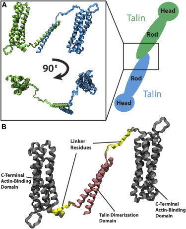
The C-terminus residues of the talin rod domain are used in MD simulations. (A) Two talin monomers (blue and green) are connected at their C-terminus. The C-terminus region consists of a two helix dimerization domain connected to a nearby helical region (inset). Two viewpoints of the C-terminus region are shown with each monomer colored either green or blue. (B) The structure of the nearby actin-binding helical bundle is taken from PDB ID 1SJW (24) (black) and the structure of the dimerization domain itself is taken from PDB ID 2QDQ (24) (pink). The linker region (yellow) connecting these two segments was modeled and added to the structure. To see this figure in color, go online.
Flexibility at the talin C-terminus
To determine the flexibility of the C-terminus region several MD simulation trials were produced. No external constraints or forces were used in these trials. Simulation until equilibration (over 5 ns) in each of the trials showed flexibility in the homology modeled linker region between the dimerization domain and the actin-binding bundle (Fig. 2). Flexibility was also seen in two other regions of the protein (peaks in root mean-square deviation (RMSD)). These regions correspond to loops connecting α-helices in the actin-binding domain, and their flexibility is not expected to impact the talin dimer orientation. In contrast to the loop regions, flexibility at the linker region suggests possible flexibility in the talin dimer orientation.
Figure 2.
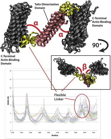
Five trials of the C-terminus region from the talin dimer were simulated in equilibrium with no external constraints. Shown in the top is the final structure after equilibration from each of the five trials after structural alignment. The α-angle describes the angle between the dimerization domain (pink) and the actin-binding helical bundle (black) within the plane shown. Inset shows the same aligned five structures rotated 90°. The β-angle describes the angle between the dimerization helices and the bundle when moving in this rotated plane. The average fluctuations of each residue across both monomers and five trials are calculated and plotted (lower panel). Peaks in the RMSD represent regions undergoing high fluctuation. Each linker between helices from the helical bundle along with the larger linker between the bundle and the dimerization helices undergo the largest fluctuation and are predicted to be the flexible regions. To see this figure in color, go online.
Residues 2484 to 2495 of the C-terminus end make up the flexible linker (Fig. S1 in the Supporting Material). These 12 residues lack an inherent structure. In one simulation two stabilizing interfaces were formed at the linker regions (Fig. S1 B), but no consistent structure was formed across both linker regions and five trials. The flexibility at the linker region likely impacted the observed overall flexibility of the C-terminus domains.
Structural alignment of the five different equilibrated structures shows the C-terminus region can adopt a variety of angles between the dimerization domain and the helical bundle (Fig. 2). Two orthogonal angles can be defined between the dimerization domain and the actin-binding helical bundle: the α-angle, the in-plane angle between the dimerization domain and the bundle (Fig. 2), is defined by residues Q2529, D2482, and G2374; and the β-angle, the out-of-plane angle between the dimerization domain and the bundle (Fig. 2, inset), is defined by Q2527, I2499, and D2482. Changes in the two angles throughout the simulation were quantified (Fig. S1 and Fig. S2). Across the different simulation trials, the α-angle tended to increase after equilibration (Fig. S2 A), whereas the β-angle tended to decrease after equilibration (Fig. S2 B). The trials showed more variability among the α-angle than the β-angle, suggesting more flexibility in the in-plane elongation of the talin dimer. To determine regions of flexibility the average fluctuation of each residue (RMSD per residue) is calculated for all trails (Fig. 2). Two fluctuation values are reported for each structure, one for each talin monomer. The results show flexibility in the C-terminus region and is demonstrated by i), the linker between helices in the helical bundle; and ii), the linker region between the bundle domain and the dimerization domain. This flexibility is expected given the unstructured nature of the linker region (Fig. S1). Given its flexibility, any conformational change at the C-terminus region is predicted to present as changes in the angle between the bundle and the dimerization helices and perhaps stretching of the linker region.
Talin dimer conformational changes after mechanical load
The orientation that the two actin-binding bundles adopt relative to the dimerization helices at the C-terminus region could govern the orientation of the two talin monomers relative to each other. The flexibility at the linker between the dimerization helix and the actin-binding bundle suggests a variety of orientations. To determine the impact of mechanical load on the specific orientation adopted, MD models are used to simulate the force-induced conformational changes at the C-terminus.
At the focal adhesion, the talin dimer is likely cross-linking two ECM-bound integrins (40). Forces from outside the cell could either move an integrin apart from the cross-linked integrin (Fig. 3, inset) or move the two integrins toward each other (Fig. 4, inset). In the case where the integrins are forced apart from each other the resultant of that force would be the stretching of the talin dimer C-terminus region. This force is simulated in silico by applying a force on one monomer away from the other monomer. Residues near the end of each monomer are likely to form stabilizing interactions with the adjacent helical bundle on the rod domain—residues K2445, D2385, E2369, and D2300—are the direct subjects of force at one end, and the same residues are harmonically held at the other end (Fig. 3). A stretching velocity is applied at a constant rate of 1 m/s for 10 ns. After stretch, the C-terminus region shows little unfolding of the helical structure in either the actin-binding bundle or the dimerization helices. Once the α-angle is increased from 48° to 166° (Fig. S3 A) the actin-binding bundle closest to the pull has reoriented itself relative to the dimerization helices. With continued stretch, the other actin-binding bundle would likely reorient as well. The flexible linker region becomes extended by the end of the simulation. The flexibility of the linker region allows the C-terminus region (and potentially the entire talin dimer) to adopt a new conformation in response to external stress. A structure of the talin C-terminus after extension is suggested (Fig. 3).
Figure 3.

The talin dimer can potentially adopt a number of different orientations. To test the impact of mechanical load on the dimer orientation a pulling force is applied to the C-terminus region of talin to simulate exposure of talin to an external stress. One possible source of this external stress could be the movement of an ECM-bound integrin away from another while cross-linked by talin. The resulting conformational change at the C-terminus region suggests talin adopts an elongated conformation after exposure to the stretching force. The conformational shift to an elongated conformation is a mode of talin mechanosensing. ECM forces on integrins can be translated to changes within the cell through elongation of the talin dimer. Shown in the top inset is a schematic of the source of an elongating force on talin. Shown in the bottom inset is a schematic of the impact of the elongate talin dimer structure on allowing talin to cross-link more separated integrins. Each monomer is shown in either green or blue. To see this figure in color, go online.
Figure 4.
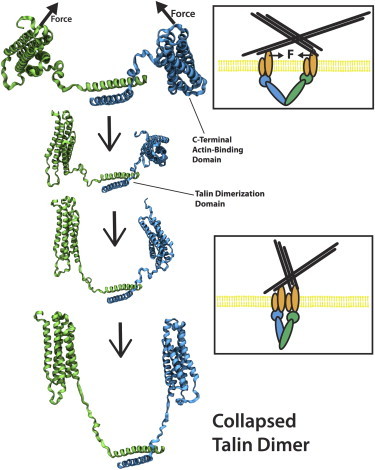
The talin dimer can potentially adopt a collapse conformation if the two talin head domains are forced together by the ECM-bound integrins. ECM forces that would push two integrins together are simulated using MD models. The results show the C-terminus region of the talin dimer adopts a collapse conformation (bottom rendered figure). Flexibility in the C-terminus region allows the talin dimer to change its orientation in response to mechanical load. Shown in the top inset is a schematic of the source of a force moving two integrins toward each other. Shown in the bottom inset is a schematic of the possible orientation of the talin dimer if two integrins move toward each other. Each monomer is shown in green or blue. To see this figure in color, go online.
The movement of two integrins toward each other would result in a force at the C-terminus region on both actin-binding bundles toward each other. We simulate this force by applying a force at residues K2445, D2385, E2369, and D2300 at the ends of both bundles in a common direction. To prevent translation of the entire complex residues 2497 and 2529 at the ends of each dimerization helix are harmonically constrained. The pull direction is defined by the vector from the average of the held residues toward the average of the pulled residues. A constant velocity of 1 m/s is used to simulate the conformational changes within 10 ns. The resulting conformation (Fig. 4) shows the two actin-binding bundles have collapsed near each other, the linker region has extended, and little helical structure is lost at either the actin-binding bundle or the dimerization helices. The β-angle between the dimerization helices and both actin-binding bundles is decreased from 132° to 81° and from 150° to 116°, respectively (Fig. S3 B). The forcing of the two integrins toward each other is likely to cause the C-terminus region of the talin dimer cross-linking the integrins (and likely the entire talin rod domain) to collapse onto each other and adopt the conformation predicted form simulation (Fig. 4). Comparison of α-angle and β-angle changes from equilibration to changes from simulation suggests both the elongation of the talin dimer from integrins forced apart and the collapse of the talin dimer from integrins forced together can be consistent with the conformational flexibility at the C-terminus region.
Free energy profile of talin dimer elongation
To thermodynamically determine the likelihood of a talin dimer C-terminus region elongation, and more directly evaluate the impact of its flexibility, we used umbrella sampling (36) to determine the PMF for a transition of the talin dimer from our initial guessed structure (Fig. 1) to the predicted elongated structure (Fig. 3). Calculation of the PMF shows that there is a free energy decrease after elongation of the C-terminus structure of around 16 KT (Fig. S4). This suggests elongation of the dimerization domain is favorable and could be adopted with only kinetic forces. Movement of two integrins bridged by a talin dimer apart would more easily result in reorientation of the talin dimer to an elongated conformation than movement of two integrins bridged by talin toward each other. This is consistent with the level of forces needed to achieve both conformational changes within 10 ns of simulation (Fig. S5). Although the magnitude of these forces are not useful—the rate of the conformational changes in vivo would be orders of magnitude slower than the rates used in this study—the difference in force between the two conformational changes can be analyzed. The free energy profile and the difference in forces suggest that a higher magnitude force will be necessary to collapse the talin dimer than to elongate the structure.
Discussion
MD simulation of the dimerization domain of talin, and its nearby C-terminus region demonstrated i), the flexibility of the linker between the dimerization helices and the rod domain helical bundles (Fig. 2); ii), the ability of ECM-induced forces to regulate the orientation of the talin rod domains relative to the dimerization helices (Figs. 3 and 4), iii), a predicted structure of an elongated talin dimer (Fig. 3); iv), a predicted structure of a collapse talin dimer (Fig. 4); and v), the favorability of elongation of the talin dimer (Fig. S4). Taken together, the simulations establish the possibility of a second mode of talin mechanosensing: the talin dimer could alter its orientation in response to forces, such as those from the ECM or from some other external source.
A number of studies have considered the possibility of talin mechanosensing (16,27,28). Initially, MD simulation of a helical bundle from the talin rod showed that the cryptic VBS can become activated after mechanical stress (17). Thereafter, experimental studies confirmed the suggestion and demonstrated that stretching of a single talin rod domain would activate that domain for binding to vinculin (28,41). Other researchers have also addressed this possibility and confirmed the suggestion further (18,27,42,43). The force that would stretch a talin rod domain would result from an actin filament (43). Talin can link integrin at its head domain and link actin at the C-terminus region actin-binding bundle. Movement of the actin filament (after linking to the talin C-terminus) or contraction of the actin filament would result in stretching of a talin (44). There are 11 cryptic VBS within the talin rod. The stretch of talin would activate each rod for binding the vinculin and thereby a new actin filament (45) (Fig. 5 A). This first mode of talin mechanosensing is a response to forces that are initiated from within the cell, likely by myosin contraction (46).
Figure 5.
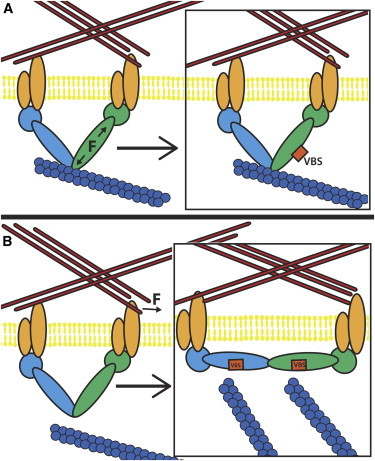
Talin can have two modes of mechanosensing: (A) The application of a stretching force across a single monomer could result in the exposure of cryptic VBS. Shown here is a schematic depicting the force across a talin monomer (green) from contraction of an attached actin filament (blue) leading to exposure of a VBS (red). (B) The application of a force on the talin dimer can cause reorientation of the dimer. Shown here is a schematic depicting the forcing of an integrin away from another by the ECM and the resulting reorientation of the talin dimer to an elongated conformation. In the elongated conformation, more actin filaments can link to the talin dimer as more VBS are available for activation and linking to actin via vinculin. To see this figure in color, go online.
The second mode of talin mechanosensing is likely to be a response to forces that are initiated from without the cell, likely from ECM movement (Fig. 4 B). The talin dimer likely adopts a more elongated structure when cross-linking or bridging to ECM-bound integrins (Fig. 4). This notion is supported both by the PMF calculated in this study (Fig. S4) and the small-angle x-ray scattering result from Gingras et al (24). As two integrins are forced together the talin dimer is forced to adopt a new more compact orientation. The C-terminus region is likely to adopt a compact conformation with the two helical rod domains collapsed onto each other (Fig. 3). If the other rod domain regions continue from the helical bundle in the C-terminus region, the talin protein will then adopt a conformation with the two rod domains that collapse onto each other. The collapsed conformation reduces the number of actin filaments that could bind the talin dimer and VBS from the two monomers and would be likely binding to the same actin filaments (Fig. 5 B). In contrast, elongation of the talin dimer and the elongated orientation of the C-terminus region would likely allow for each VBS (22 total in the talin dimer) to bind a unique actin filament (Fig. 5 B). The second mode of talin mechanosensing, in response to forces from outside the cell, presents itself as a change in the orientation of the talin monomers relative to each other. Not only is the conformation of the rod domain near each VBS force dependent, but the orientation of the talin dimer is also force dependent. That there is an orientation shift resulting from external force is not surprising and is consistent with what would be expected intuitively. However, in the absence of the results from this simulation, there would be no expectation that an elongation event would be more likely than a collapse event. Characterizing that the elongation is a more likely domain shift is a valuable contribution of this work.
The results from this study, and the suggestion of the two mechanosensing modes of talin illustrate some of the dynamic aspects of the talin dimer. The dynamic picture is a complement to recent work by Kanchanawong and Waterman (47) aimed at illustrating in detail the structure of talin in focal adhesions. The combination of a dynamic model of mechanosensing and a static model of talin structure can illuminate the critical role of talin in focal adhesion formation and mechanosensing.
It is interesting to consider the possible sources of a force that would move integrins apart or close together. One possibility is that an external force on the tissue itself is transduced to the integrins through the ECM of the tissue (48–50). Such a force could be experimentally controlled, either in vivo or in vitro, and the predicted talin dimer conformation could be tested. Another possibility would have the second mode of talin mechanosensing dominate mechanotransduction in endothelial cells (51) where shear stress on the ECM and integrins would cause reorientation of the talin dimer.
The second mode of talin mechanosensing is independent of myosin contraction. Even without actin filaments bound either to the C-terminal region actin-binding site or another actin-binding site, the talin dimer will likely react by dimer reorientation in response to mechanical stimulation from outside the cell. This is of particular importance in thinking about focal adhesion-like structures that are formed in a cell immersed in a 3-D matrix (16,52,53). This focal-adhesion is smaller, and is shown to form in the absence of myosin contraction (16). Furthermore, talin is consistently recruited to these structures but not vinculin. Vinculin plays a crucial role in connecting actin filaments to the talin rod, and has been shown previously to potentially be mechanosensing (54–58). In the absence of vinculin at the 3-D focal adhesions, and in the absence of myosin contraction, talin can maintain a mechanosensing role through reorientation of its dimer (Fig. 5 B). This would then predict that the focal adhesions at 3-D interfaces are also mechanoresponsive.
The suggestions from the MD simulations presented here are consistent with a number of studies aimed at understanding the talin structure and the overall structure of the focal adhesions. In their presentation of the structures of the dimerization helices and the nearby actin-binding bundle, Gingras et al (24) considered the orientation of the talin dimer. Their considerations suggest talin to adopt a more elongated orientation at the C-terminus region and further suggest several talin dimer orientations to be possible. The results in this study consider a modeled structure of the linker region but confirm that the elongated dimer orientation is favorable (Fig. S4). The flexibility of the linker region allows for other orientations to be adopted and for the mechanosensing response.
Other studies aimed at understanding the impact of ECM organization on focal adhesion structure suggest a separation of at most 60 nm between successive RGD residues in ECM is necessary to form stable and larger focal adhesions (59–61). Earlier studies also measured the talin dimer to be likely 56 ± 7 nm in length (23). The length of the dimer has been shown to be dependent on the ionic strength of the solvent. The 56–60 nm length corresponds to an elongated talin dimer orientation. RGC residues placed further than that are beyond the reach of even an elongated talin dimer. By cross-linking two integrins the talin dimer allows a scaffold onto which the focal adhesion can develop (62). That the talin dimer could adopt other sizes with different ionic solvent strengths supports our notion of other talin dimer orientations, but also suggests additional structural mechanisms could be contributing to the length of the talin dimer, beyond just the orientation at the C-terminus region.
Understanding the structure and the orientation of the talin dimer can impact the outstanding understanding of focal adhesion formation. The simulations presented here suggest that multiple modes of mechanosensing exist, at least for the talin protein. The source of the mechanical stimulation, the magnitude of the mechanical stimulation, and the direction of any force can differentiate which mode of mechanosensing is operating. In the case of an ECM-based stimulus that would occur in the absence of a mechanical stretch, it is likely that the talin dimer will reorient itself. In the case of a myosin-induced actin filament contraction, stretch of the talin rod and activation of individual VBS is likely. The two modes will act together. Perhaps the talin dimer reorientation occurs initially in response to smaller activating forces from outside the cell. This would allow a foundation to be formed for focal adhesion formation on the talin dimer. Later forces across the talin dimer originating from inside the cell could contribute to recruitment of a multitude of vinculin to this scaffold. And with the recruitment of vinculin, other actin filaments, and other focal adhesion forming molecules the focal adhesion would grow and mature. In the case of prolonged exposure of talin to an external or internal force, there are at least two possible scenarios 1), the prolonged external force is able to overcome molecular forces holding talin in the elongated conformation, and talin is unfolded entirely; or 2), the recruitment of additional focal adhesion forming molecules to the site of force exposure further stabilizes the link, and talin is held in a stable folded conformation. Both scenarios are theoretically possible, and would be consistent with the results from this study.
The talin structure considered in this study restricted the predictions of force-induced orientation changes to only the C-terminus residues of talin. Although a complete structure of the entire talin protein is not yet solved, a creative effort to model the missing residues, or build approximate structures (or even solve crystal structures) of the remaining regions from talin would extend the analysis presented here to the entire talin structure. Such a simulation could expand our predictions of the force-induced talin dimer orientation changes. Beyond further in silico studies, experimental studies are called for to test the predictions presented here and investigate the possibility of a second mode of talin mechanosensing. As our understanding of the focal adhesion mechanosensors advances, we can begin to arrive at a more complete picture of the focal adhesion, of cell-substrate adhesion, and of the mechanisms by which the cell can interact with its mechanical environment.
Acknowledgments
Financial support by a National Science Foundation CAREER award (CBET-0955291) is gratefully acknowledged. We appreciate technical support and contributions from Alejandro Schuler and other members of the Molecular Cell Biomechanical Laboratory.
Supporting Material
References
- 1.Hoffman B.D., Grashoff C., Schwartz M.A. Dynamic molecular processes mediate cellular mechanotransduction. Nature. 2011;475:316–323. doi: 10.1038/nature10316. [DOI] [PMC free article] [PubMed] [Google Scholar]
- 2.Jahed Z., Shams H., Mofrad M.R.K. Mechanotransduction pathways linking the extracellular matrix to the nucleus. Int. Rev. Cell Mol. Biol. 2014;310:171–220. doi: 10.1016/B978-0-12-800180-6.00005-0. [DOI] [PubMed] [Google Scholar]
- 3.Kumar S., Weaver V.M. Mechanics, malignancy, and metastasis: the force journey of a tumor cell. Cancer Metastasis Rev. 2009;28:113–127. doi: 10.1007/s10555-008-9173-4. [DOI] [PMC free article] [PubMed] [Google Scholar]
- 4.Discher D.E., Mooney D.J., Zandstra P.W. Growth factors, matrices, and forces combine and control stem cells. Science. 2009;324:1673–1677. doi: 10.1126/science.1171643. [DOI] [PMC free article] [PubMed] [Google Scholar]
- 5.Ngu H., Feng Y., Yin F.C. Effect of focal adhesion proteins on endothelial cell adhesion, motility and orientation response to cyclic strain. Ann. Biomed. Eng. 2010;38:208–222. doi: 10.1007/s10439-009-9826-7. [DOI] [PubMed] [Google Scholar]
- 6.Zaidel-Bar R., Ballestrem C., Geiger B. Early molecular events in the assembly of matrix adhesions at the leading edge of migrating cells. J. Cell Sci. 2003;116:4605–4613. doi: 10.1242/jcs.00792. [DOI] [PubMed] [Google Scholar]
- 7.Askari J.A., Tynan C.J., Humphries M.J. Focal adhesions are sites of integrin extension. J. Cell Biol. 2010;188:891–903. doi: 10.1083/jcb.200907174. [DOI] [PMC free article] [PubMed] [Google Scholar]
- 8.Humphries J.D., Wang P., Ballestrem C. Vinculin controls focal adhesion formation by direct interactions with talin and actin. J. Cell Biol. 2007;179:1043–1057. doi: 10.1083/jcb.200703036. [DOI] [PMC free article] [PubMed] [Google Scholar]
- 9.Peter S.J., Mofrad M.R.K. Computational modeling of axonal microtubule bundles under tension. Biophys. J. 2012;102:749–757. doi: 10.1016/j.bpj.2011.11.4024. [DOI] [PMC free article] [PubMed] [Google Scholar]
- 10.Mehrbod M., Mofrad M.R. On the significance of microtubule flexural behavior in cytoskeletal mechanics. PLoS ONE. 2011;6:e25627. doi: 10.1371/journal.pone.0025627. [DOI] [PMC free article] [PubMed] [Google Scholar]
- 11.Azimi M., Jamali Y., Mofrad M.R.K. Accounting for diffusion in agent based models of reaction-diffusion systems with application to cytoskeletal diffusion. PLoS ONE. 2011;6:e25306. doi: 10.1371/journal.pone.0025306. [DOI] [PMC free article] [PubMed] [Google Scholar]
- 12.Modarres H., Mofrad M. Filamin: a structural and functional biomolecule with important roles in cell biology, signaling and mechanics. MCB Mol. Cell. Biomech. 2014;11:039–065. [PubMed] [Google Scholar]
- 13.Moore S.W., Roca-Cusachs P., Sheetz M.P. Stretchy proteins on stretchy substrates: the important elements of integrin-mediated rigidity sensing. Dev. Cell. 2010;19:194–206. doi: 10.1016/j.devcel.2010.07.018. [DOI] [PMC free article] [PubMed] [Google Scholar]
- 14.Jiang G., Giannone G., Sheetz M.P. Two-piconewton slip bond between fibronectin and the cytoskeleton depends on talin. Nature. 2003;424:334–337. doi: 10.1038/nature01805. [DOI] [PubMed] [Google Scholar]
- 15.Bruinsma R. Theory of force regulation by nascent adhesion sites. Biophys. J. 2005;89:87–94. doi: 10.1529/biophysj.104.048280. [DOI] [PMC free article] [PubMed] [Google Scholar]
- 16.Fraley S.I., Feng Y., Wirtz D. A distinctive role for focal adhesion proteins in three-dimensional cell motility. Nat. Cell Biol. 2010;12:598–604. doi: 10.1038/ncb2062. [DOI] [PMC free article] [PubMed] [Google Scholar]
- 17.Lee S.E., Kamm R.D., Mofrad M.R. Force-induced activation of talin and its possible role in focal adhesion mechanotransduction. J. Biomech. 2007;40:2096–2106. doi: 10.1016/j.jbiomech.2007.04.006. [DOI] [PubMed] [Google Scholar]
- 18.Critchley D.R., Gingras A.R. Talin at a glance. J. Cell Sci. 2008;121:1345–1347. doi: 10.1242/jcs.018085. [DOI] [PubMed] [Google Scholar]
- 19.Gingras A.R., Ziegler W.H., Emsley J. Mapping and consensus sequence identification for multiple vinculin binding sites within the talin rod. J. Biol. Chem. 2005;280:37217–37224. doi: 10.1074/jbc.M508060200. [DOI] [PubMed] [Google Scholar]
- 20.Hemmings L., Rees D.J., Critchley D.R. Talin contains three actin-binding sites each of which is adjacent to a vinculin-binding site. J. Cell Sci. 1996;109:2715–2726. doi: 10.1242/jcs.109.11.2715. [DOI] [PubMed] [Google Scholar]
- 21.Roberts G.C., Critchley D.R. Structural and biophysical properties of the integrin-associated cytoskeletal protein talin. Biophys Rev. 2009;1:61–69. doi: 10.1007/s12551-009-0009-4. [DOI] [PMC free article] [PubMed] [Google Scholar]
- 22.Goldmann W.H., Bremer A., Isenberg G. Native talin is a dumbbell-shaped homodimer when it interacts with actin. J. Struct. Biol. 1994;112:3–10. doi: 10.1006/jsbi.1994.1002. [DOI] [PubMed] [Google Scholar]
- 23.Winkler J., Lünsdorf H., Jockusch B.M. Energy-filtered electron microscopy reveals that talin is a highly flexible protein composed of a series of globular domains. Eur. J. Biochem. 1997;243:430–436. doi: 10.1111/j.1432-1033.1997.0430a.x. [DOI] [PubMed] [Google Scholar]
- 24.Gingras A.R., Bate N., Critchley D.R. The structure of the C-terminal actin-binding domain of talin. EMBO J. 2008;27:458–469. doi: 10.1038/sj.emboj.7601965. [DOI] [PMC free article] [PubMed] [Google Scholar]
- 25.Lee S.E., Chunsrivirot S., Mofrad M.R. Molecular dynamics study of talin-vinculin binding. Biophys. J. 2008;95:2027–2036. doi: 10.1529/biophysj.107.124487. [DOI] [PMC free article] [PubMed] [Google Scholar]
- 26.Golji J., Lam J., Mofrad M.R. Vinculin activation is necessary for complete talin binding. Biophys. J. 2011;100:332–340. doi: 10.1016/j.bpj.2010.11.024. [DOI] [PMC free article] [PubMed] [Google Scholar]
- 27.Hytönen V.P., Vogel V. How force might activate talin’s vinculin binding sites: SMD reveals a structural mechanism. PLOS Comput. Biol. 2008;4:e24. doi: 10.1371/journal.pcbi.0040024. [DOI] [PMC free article] [PubMed] [Google Scholar]
- 28.del Rio A., Perez-Jimenez R., Sheetz M.P. Stretching single talin rod molecules activates vinculin binding. Science. 2009;323:638–641. doi: 10.1126/science.1162912. [DOI] [PMC free article] [PubMed] [Google Scholar]
- 29.Elliott P.R., Goult B.T., Barsukov I.L. The Structure of the talin head reveals a novel extended conformation of the FERM domain. Structure. 2010;18:1289–1299. doi: 10.1016/j.str.2010.07.011. [DOI] [PMC free article] [PubMed] [Google Scholar]
- 30.Pettersen E.F., Goddard T.D., Ferrin T.E. UCSF Chimera—a visualization system for exploratory research and analysis. J. Comput. Chem. 2004;25:1605–1612. doi: 10.1002/jcc.20084. [DOI] [PubMed] [Google Scholar]
- 31.Phillips J.C., Braun R., Schulten K. Scalable molecular dynamics with NAMD. J. Comput. Chem. 2005;26:1781–1802. doi: 10.1002/jcc.20289. [DOI] [PMC free article] [PubMed] [Google Scholar]
- 32.Humphrey W., Dalke A., Schulten K. VMD: visual molecular dynamics. J. Mol. Graph. 1996;14:33–38. doi: 10.1016/0263-7855(96)00018-5. 27–28. [DOI] [PubMed] [Google Scholar]
- 33.Kraeutler V., Gunsteren W.F., Huenenberger P.H. A fast SHAKE algorithm to solve distance constraint equations for small molecules in molecular dynamics simulations. J. Comput. Chem. 2001;22:501–508. [Google Scholar]
- 34.Lazaridis T., Karplus M. Effective energy function for proteins in solution. Proteins. 1999;35:133–152. doi: 10.1002/(sici)1097-0134(19990501)35:2<133::aid-prot1>3.0.co;2-n. [DOI] [PubMed] [Google Scholar]
- 35.Lee E.H., Hsin J., Schulten K. Discovery through the computational microscope. Structure. 2009;17:1295–1306. doi: 10.1016/j.str.2009.09.001. [DOI] [PMC free article] [PubMed] [Google Scholar]
- 36.Torrie G., Valleau J. Nonphysical sampling distributions in Monte Carlo free-energy estimation: umbrella sampling. J. Comput. Phys. 1977;23:187–199. [Google Scholar]
- 37.Van Der Spoel D., Lindahl E., Berendsen H.J.C. GROMACS: fast, flexible, and free. J. Comput. Chem. 2005;26:1701–1718. doi: 10.1002/jcc.20291. [DOI] [PubMed] [Google Scholar]
- 38.Kumar S., Rosenberg J.M., Kollman P.A. THE weighted histogram analysis method for free-energy calculations on biomolecules. I. The method. J. Comput. Chem. 1992;13:1011–1021. [Google Scholar]
- 39.Cavasotto C.N., Phatak S.S. Homology modeling in drug discovery: current trends and applications. Drug Discov. Today. 2009;14:676–683. doi: 10.1016/j.drudis.2009.04.006. [DOI] [PubMed] [Google Scholar]
- 40.Mehrbod M., Trisno S., Mofrad M.R. On the activation of integrin αIIbβ3: outside-in and inside-out pathways. Biophys J. 2013;105:1304–1315. doi: 10.1016/j.bpj.2013.07.055. [DOI] [PMC free article] [PubMed] [Google Scholar]
- 41.Golji J., Wendorff T., Mofrad M.R. Phosphorylation primes vinculin for activation. Biophys. J. 2012;102:2022–2030. doi: 10.1016/j.bpj.2012.01.062. [DOI] [PMC free article] [PubMed] [Google Scholar]
- 42.Patel B., Gingras A.R., Critchley D.R. The activity of the vinculin binding sites in talin is influenced by the stability of the helical bundles that make up the talin rod. J. Biol. Chem. 2006;281:7458–7467. doi: 10.1074/jbc.M508058200. [DOI] [PubMed] [Google Scholar]
- 43.Carragher N.O., Frame M.C. Focal adhesion and actin dynamics: a place where kinases and proteases meet to promote invasion. Trends Cell Biol. 2004;14:241–249. doi: 10.1016/j.tcb.2004.03.011. [DOI] [PubMed] [Google Scholar]
- 44.Geiger B., Spatz J.P., Bershadsky A.D. Environmental sensing through focal adhesions. Nat. Rev. Mol. Cell Biol. 2009;10:21–33. doi: 10.1038/nrm2593. [DOI] [PubMed] [Google Scholar]
- 45.Golji J., Mofrad M.R.K. The interaction of vinculin with actin. PLOS Comput. Biol. 2013;9:e1002995. doi: 10.1371/journal.pcbi.1002995. [DOI] [PMC free article] [PubMed] [Google Scholar]
- 46.Gardel M.L., Schneider I.C., Waterman C.M. Mechanical integration of actin and adhesion dynamics in cell migration. Annu. Rev. Cell Dev. Biol. 2010;26:315–333. doi: 10.1146/annurev.cellbio.011209.122036. [DOI] [PMC free article] [PubMed] [Google Scholar]
- 47.Kanchanawong P., Waterman C.M. Advances in light-based imaging of three-dimensional cellular ultrastructure. Curr. Opin. Cell Biol. 2012;24:125–133. doi: 10.1016/j.ceb.2011.11.010. [DOI] [PMC free article] [PubMed] [Google Scholar]
- 48.Mehrbod M., Mofrad M.R.K. Localized lipid packing of transmembrane domains impedes integrin clustering. PLOS Comput. Biol. 2013;9:e1002948. doi: 10.1371/journal.pcbi.1002948. [DOI] [PMC free article] [PubMed] [Google Scholar]
- 49.Jamali Y., Jamali T., Mofrad M.R. An agent based model of integrin clustering: exploring the role of ligand clustering, integrin homo-oligomerization, integrin-ligand affinity, membrane crowdedness and ligand mobility. J. Comput. Chem. 2012;244:264–278. [Google Scholar]
- 50.Yoon S.-H., Kim Y.K., Mofrad M.R.K. Passive control of cell locomotion using micropatterns: the effect of micropattern geometry on the migratory behavior of adherent cells. Lab Chip. 2012;12:2391–2402. doi: 10.1039/c2lc40084g. [DOI] [PubMed] [Google Scholar]
- 51.Pahakis M.Y., Kosky J.R., Tarbell J.M. The role of endothelial glycocalyx components in mechanotransduction of fluid shear stress. Biochem. Biophys. Res. Commun. 2007;355:228–233. doi: 10.1016/j.bbrc.2007.01.137. [DOI] [PMC free article] [PubMed] [Google Scholar]
- 52.Cukierman E., Pankov R., Yamada K.M. Taking cell-matrix adhesions to the third dimension. Science. 2001;294:1708–1712. doi: 10.1126/science.1064829. [DOI] [PubMed] [Google Scholar]
- 53.Kubow K.E., Horwitz A.R. Reducing background fluorescence reveals adhesions in 3D matrices. Nat. Cell Biol. 2011;13:3–5. doi: 10.1038/ncb0111-3. author reply 5–7. [DOI] [PMC free article] [PubMed] [Google Scholar]
- 54.Golji J., Mofrad M.R. A molecular dynamics investigation of vinculin activation. Biophys. J. 2010;99:1073–1081. doi: 10.1016/j.bpj.2010.05.024. [DOI] [PMC free article] [PubMed] [Google Scholar]
- 55.Ziegler W.H., Liddington R.C., Critchley D.R. The structure and regulation of vinculin. Trends Cell Biol. 2006;16:453–460. doi: 10.1016/j.tcb.2006.07.004. [DOI] [PubMed] [Google Scholar]
- 56.Grashoff C., Hoffman B.D., Schwartz M.A. Measuring mechanical tension across vinculin reveals regulation of focal adhesion dynamics. Nature. 2010;466:263–266. doi: 10.1038/nature09198. [DOI] [PMC free article] [PubMed] [Google Scholar]
- 57.Shams H., Golji J., Mofrad M.R. A molecular trajectory of α-actinin activation. Biophys. J. 2012;103:2050–2059. doi: 10.1016/j.bpj.2012.08.044. [DOI] [PMC free article] [PubMed] [Google Scholar]
- 58.Mofrad M.R.K., Kamm R.D., editors. Cellular Mechanotransduction: Diverse Perspectives From Molecules to Tissues. Cambridge University Press; NY: 2014. [Google Scholar]
- 59.Schvartzman M., Palma M., Wind S.J. Nanolithographic control of the spatial organization of cellular adhesion receptors at the single-molecule level. Nano Lett. 2011;11:1306–1312. doi: 10.1021/nl104378f. [DOI] [PMC free article] [PubMed] [Google Scholar]
- 60.Massia S.P., Hubbell J.A. An RGD spacing of 440 nm is sufficient for integrin alpha V beta 3-mediated fibroblast spreading and 140 nm for focal contact and stress fiber formation. J. Cell Biol. 1991;114:1089–1100. doi: 10.1083/jcb.114.5.1089. [DOI] [PMC free article] [PubMed] [Google Scholar]
- 61.Roca-Cusachs P., Gauthier N.C., Sheetz M.P. Clustering of alpha(5)beta(1) integrins determines adhesion strength whereas alpha(v)beta(3) and talin enable mechanotransduction. Proc. Natl. Acad. Sci. USA. 2009;106:16245–16250. doi: 10.1073/pnas.0902818106. [DOI] [PMC free article] [PubMed] [Google Scholar]
- 62.Dubash A.D., Menold M.M., Burridge K. Chapter 1. Focal adhesions: new angles on an old structure. Int. Rev. Cell Mol. Biol. 2009;277:1–65. doi: 10.1016/S1937-6448(09)77001-7. [DOI] [PubMed] [Google Scholar]
Associated Data
This section collects any data citations, data availability statements, or supplementary materials included in this article.