

Significance
T7 phage has been used as a model system to study dsDNA virus capsid assembly and maturation. Yet, atomic capsid models and details of capsid transformations are not elucidated. From our cryo-EM study we have derived near-atomic resolution reconstructions of the DNA-free procapsid, a DNA packaging intermediate, and the DNA-packaged, mature phage capsid. From these structures, we have derived the first near-atomic-level model of T7 capsid maturation. The structural knowledge obtained from this study can serve as a platform for analysis of other dsDNA viruses as well as a platform for the development of molecular tools such as improved phage display systems.
Keywords: bacteriophage T7 maturation, DNA packaging intermediates, noncovalent topological linking, procapsid, single-particle cryo-EM
Abstract
Many dsDNA viruses first assemble a DNA-free procapsid, using a scaffolding protein-dependent process. The procapsid, then, undergoes dramatic conformational maturation while packaging DNA. For bacteriophage T7 we report the following four single-particle cryo-EM 3D reconstructions and the derived atomic models: procapsid (4.6-Å resolution), an early-stage DNA packaging intermediate (3.5 Å), a later-stage packaging intermediate (6.6 Å), and the final infectious phage (3.6 Å). In the procapsid, the N terminus of the major capsid protein, gp10, has a six-turn helix at the inner surface of the shell, where each skewed hexamer of gp10 interacts with two scaffolding proteins. With the exit of scaffolding proteins during maturation the gp10 N-terminal helix unfolds and swings through the capsid shell to the outer surface. The refolded N-terminal region has a hairpin that forms a novel noncovalent, joint-like, intercapsomeric interaction with a pocket formed during shell expansion. These large conformational changes also result in a new noncovalent, intracapsomeric topological linking. Both interactions further stabilize the capsids by interlocking all pentameric and hexameric capsomeres in both DNA packaging intermediate and phage. Although the final phage shell has nearly identical structure to the shell of the DNA-free intermediate, surprisingly we found that the icosahedral faces of the phage are slightly (∼4 Å) contracted relative to the faces of the intermediate, despite the internal pressure from the densely packaged DNA genome. These structures provide a basis for understanding the capsid maturation process during DNA packaging that is essential for large numbers of dsDNA viruses.
Many dsDNA viruses, including tailed phages and herpes viruses, initially assemble a DNA-free procapsid with assistance of a network of scaffold proteins. Accompanying the exit of scaffolding proteins during subsequent ATP-driven DNA packaging, the icosahedral shell of the procapsid undergoes dramatic conformational changes and matures into a typically larger and more angular shell of the infectious phage (1–6). However, structural details, including those of capsid intermediates, are limited to the phage HK97 system (5, 7–9), for which recombinantly produced procapsid and nonphysiological conversion products were analyzed.
The packaging of the 39.937-kbp DNA genome of the short-tail Escherichia coli bacteriophage, T7, is a model for understanding basic principles common to dsDNA tailed phages and herpes viruses. The T7 system is also of interest because it has been used for popular biotechnologies, such as recombinant protein expression (10) and protein display on the capsid surface (11). The T7 capsid contains 415 copies of the major shell protein gp10 (12) that form a T = 7L icosahedral lattice. From low-resolution cryo-EM 3D reconstructions the tertiary topology of gp10 can be divided into four regions: N-arm, E-loop, A-domain, and P-domain, which together place the gp10 protein in the HK97 fold category (2, 13, 14). The T7 procapsid, capsid I, contains 110–140 molecules of scaffolding protein, gp9 (4, 15, 16). After scaffolding protein expulsion the spherical T7 capsid I expands to more angular intermediates, which are collectively called capsid II (2, 4, 14, 16–18).
Two DNA-free capsid IIs are purified in quantity sufficient for structural studies by cryo-EM (16). Both are produced during the normal process of wild-type T7 DNA packaging in vivo. One has an unusually low density during buoyant density centrifugation in a metrizamide density gradient (1.086 g/mL; metrizamide low density, or MLD, capsid II) and the other has a density as expected for hydrated proteins (1.28 g/mL; metrizamide high density, or MHD, capsid II) (16). The low density of MLD capsid II is caused by impermeability to metrizamide (789 Da) (16). The MLD capsid II particles are produced before MHD capsid II particles based on kinetic studies (16).
The DNA packaging of T7 phage starts at capsid I state where the DNA is packaged by the ATPases (gp18 and gp19) to pass through the portal (gp8) apparatus (19). By analyzing kinetics of in vivo-produced capsids, MLD capsid II was found to be the first postcapsid I capsid. MLD capsid II appears with the kinetics of an intermediate (16) but is obviously no longer in the DNA packaging pathway because it has detached from the DNA molecule that it was packaging. MLD capsid II is not produced when a nonpermissive host is infected with a T7 amber mutant defective in DNA packaging (summarized in ref. 16). Thus, MLD capsid II is an intermediate that has been altered during either cellular lysis or subsequent purification. MHD capsid II also has the appearance kinetics of an intermediate of packaging, but one that occurs later (16). Whereas MLD capsid II has the internal core stack including proteins gp8, gp14, gp15, and gp16 (16), MHD capsid II does not have the internal core stack proteins, which were presumably lost when packaged DNA exited the capsid (16).
The existence of these various capsids provides an opportunity to obtain a high-resolution (3–4 Å) analysis of structural dynamics that occur in vivo. Here we report cryo-EM structures of the shells of the following bacteriophage T7 capsids: capsid I (4.6 Å), MLD capsid II (3.5 Å), MHD capsid II (6.6 Å), and phage (3.6 Å). The two capsid II shells are the first postprocapsid, in vivo-generated shells (for any packaging system) to be subjected to high-resolution structural analysis, to our knowledge. The results reveal (i) an HK97-fold shell protein with an intracapsomere, noncovalent topological linking and another intercapsomere, joint interaction, neither interaction having been found for other dsDNA tailed phages; (ii) details of the interaction of gp9 scaffolding protein with the inner surface of the capsid I shell; (iii) a novel refolding and externalization of the N terminus of major capsid protein, gp10; and (iv) a subtle, surprising contraction of the gp10 shell in transit from MLD capsid II to phage. Based on these observations, we propose a general procapsid assembly and maturation pathway for dsDNA viruses.
Results
Electron Cryomicroscopy and 3D Reconstruction.
In this study, we used a T7 strain (T7A) with only the gp10A (345 aa) variant of the major capsid protein. This practice minimizes particle heterogeneity in relation to wild-type T7. Wild-type T7 capsids typically also contain ∼5–10% of gp10B (398 aa); gp10B is a variant of gp10 produced by translation frame-shift near the C terminus (12). We also used polylysine-coated, ultrathin, continuous carbon transmission EM (TEM) grids to improve capsid adsorption (20). We imaged capsid I, MLD capsid II, MHD capsid II, and phage particles (Fig. 1A) using cryo-EM (Table S1). To obtain high-resolution images (Fig. 1A), extra attention was paid to imaging with parallel beam illumination and comma-free alignment.
Fig. 1.
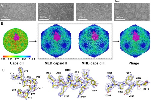
Single-particle 3D reconstructions of bacteriophage T7. (A) Cryo-EM images of capsid I, MLD capsid II, MHD capsid II, and phage. (B) Threefold surface view of corresponding 3D reconstructions. The surfaces are colored by radius. One T = 7L asymmetric unit is highlighted in magenta. (C) Electron densities of three representative regions (a loop, an α-helix, and a β-strand) of MLD capsid II structure.
All shell structures (Fig. 1B) were determined de novo using icosahedral reconstruction. The image processing and 3D reconstruction adopted truly independent refinements (21) and the resolutions were assessed using the “gold” standard FSC = 0.143 criterion (22–24). The MLD capsid II dataset gave the highest resolution at 3.5 Å (Fig. S1 and Table S1). At this resolution, the electron densities (Fig. 1C and Fig. S2) are well resolved for the majority of the regions, which allowed us to manually trace the backbone, build a full-atomic gp10 model, and refine the model. We used crystallographic refinements against the structural factors calculated from the original density map. The refined structures then were validated using standard X-ray crystallographic measurements: R-factor, Ramachandran plot, and real-space correlation coefficient, which are listed in Table S2 and Fig. S3.
The phage shell was solved at 3.6 Å resolution. Owing to its close similarity in structure to that of the MLD capsid II, the atomic model of the MLD capsid II shell was used as the starting model for the phage shell, which was then further refined against the electron densities of the phage structure. The MHD capsid II shell was solved until 6.6-Å resolution, at which point the icosahedral reconstruction was indistinguishable from that of the MLD capsid II. The increased metrizamide permeability of MHD capsid II is likely due to the loss of the portal and core stack proteins to create a large opening at the portal vertex. This loss was observed by SDS/PAGE analysis of the capsid protein compositions (16).
The capsid I electron density map was solved at 4.6-Å resolution (Fig. S1 and Table S1). In this structure, several regions were less resolved, probably reflecting flexibility of gp10 in this metastable shell and possibly also heterogeneity of the capsid I particles. The atomic model of capsid I was derived from the model of MLD capsid II by using molecular dynamics flexible fitting (MDFF) (25) and crystallographic refinements as described for MLD capsid II.
Atomic Model of Capsid I Reveals a Hidden N-Terminal Helix.
Capsid I is the most spherical capsid of the four. Capsid I has a rotationally averaged and maximum diameter (peak-to-peak distance of the shell in radial density plot) of 492 Å and 565 Å, respectively. The pentons are nearly closed, whereas the hexons have an 11- × 16-Å central opening. From the 4.6-Å cryo-EM electron density map an atomic model was built for most of the major capsid protein, gp10A (residues 22–343). Residues 1–21 were missing in the cryo-EM electron density map and assumed to be in nonunique conformations. A gp10A subunit of the capsid I shell (Fig. 2A) has conformation similar to the HK97 fold, which has now been well established among dsDNA viruses including tailed phages (1–3, 26–29) and human herpes virus (30).
Fig. 2.

Atomic models of major capsid protein gp10A. (A) Subunit g in capsid I. (B) Subunit d in MLD capsid II. The models are rainbow-colored from N (blue) to C (red) terminus. A salt bridge formed by Asp-103 and Arg-262 is shown as sticks in B. A and B are viewed from the capsid outer surface, similar to the orientation of the bottom panel in C and D. (C and D) Arrangement of subunits in a pentamer and a hexamer of the (C) capsid I shell and (D) MLD II capsid II shell in two orthogonal views (side view in top panel and top view in bottom panel). The N-helix (C) and N-arm (D) regions are colored in blue. The red asterisk indicates the P-domain/E-loop interaction of subunits e and f. (E) The section views of the asymmetric unit density (green) of capsid I. The locations of the sections, which have variable degrees of skewing, are indicated by red dashed arrows.
Using previous terminology, the T7 gp10A conformation is divided into N-helix, E-loop, P-domain, and A-domain (capsid I, Fig. 2A). The E-loop, P-domain, and A-domain are analogous to those in other bacteriophages such as HK97 and P22 (1, 8). However, the six-turn N-helix (residues 24–43) (Fig. 2A) is only sometimes found in other phage procapsids. It is present in the P22 procapsid (1) but not in the HK97 procapsid (8). The N-helix is near the inner shell surface next to the P-domain, where it is covered by the scaffolding protein, gp9, as discussed in next section (Figs. 2 A and C and 3 B and C). Furthermore, a small insertion G-loop near the carboxyl end of the P-domain spine helix in HK97 is not observed in the T7 spine helix (i.e., α2 in Fig. 2 and Fig. S4).
Fig. 3.

Interactions of scaffolding protein gp9 with major capsid protein gp10 on the inner surface of capsid I. (A) The inner surface is radially colored. The scaffolding protein, gp9, densities (blue) are found on hexamers, but not on pentamers. Scaffolding protein in the boxed region is magnified in C. The electron densities were low-pass-filtered to 7 Å for cleaner view. (B) Zoom-in view of the N-helix region. The N-helix model (sticks) is superimposed in the electron density (wire frames). (C) Zoom-in view of the electron densities of scaffolding protein HTH region found on gp10 subunit f. (D) Model of gp10 and the gp9 HTH region. The gp10 is the same subunit, f, as shown in B.
Each asymmetric unit consists of seven gp10A subunits (A–G) (Fig. 1B and Fig. 2C). The Cα rmsds of the seven subunits were at 2–4 Å (Fig. S5C illustrates the differences in conformation). Subunits a–f form a skewed hexameric capsomere in capsid I, whereas five g subunits, from adjacent asymmetric units, form a pentameric capsomere at the fivefold vertex (Fig. 2C). Owing to the skewing, the symmetry of the hexamer is reduced to twofold (Fig. 2E). Subunits b and e are located on the two short edges of the skewed hexagon and subunits a, c, d, and f occupy the four longer edges. The E-loops of subunits b, e, and g had the largest bending toward the capsid center (Fig. S5C). The hexamer skewing increased from the interior N-helix to the outer A-domain (Fig. 2E). Similar patterns of changing skewness are also found in the structures of the P22 and HK97 procapsids, although this was not discussed previously (1, 7, 31). The E-loop and P-domain interact when in neighboring subunits within the same hexamer or pentamer (Fig. S6), which provides the most intracapsomeric stability in capsid I. The interactions are mainly electrostatic. They are derived from negatively charged E-loop and positively charged outer surface residues of the P-domain. In contrast, the A-domains in hexamers have relatively little interaction with neighboring subunits owing to the skewing (Fig. 2C).
As for the threefold axes, where three neighboring capsomeres interact, the E-loops from different capsomeres directly contact each other on the outer surface and three P-domains form the inner surface (Fig. S6). In addition to the bending of the E-loop, a one-turn helix (residues 82–87) preceding β-strand βC forms only in capsid I (Fig. 2A). This short helix interacts with the P-loop of neighboring capsomere.
Previous studies of HK97 prohead I structure showed that there are significant differences among the three classes of icosahedral and quasi-threefold axes (7). However, only more subtle differences are observed among the three classes of threefold interaction in T7 capsid I (Fig. S6). In T7 capsid I, around all three classes of threefold axes, the E-loop tip of one subunit interacts with two consecutive subunits of its neighboring capsomere, one with the E-loop bending region of the threefold related subunit and another with the P-domain (P-loop between βK/βJ and α1) of the other subunit (Fig. S6). In T7 capsid I, all types of threefold axes (quasi and icosahedral) have similar center openings and adjacent twofold axes regions (Fig. S6). The similarity among the three classes of threefold axis conformations was also observed in the p22 procapsid (1).
Interactions of Scaffolding Proteins with Capsid Shell in Capsid I.
We found that the scaffolding protein, gp9, resides in the procapsid interior, as expected from previous data for HK97, P22, and T7 (1, 4, 7, 14, 31). The gp9 densities were detected as additional densities at the inner surface of hexons, but not pentons, after modeling gp10A. The volumes of these hexon-specific densities were much larger than the possible volume of the unresolved 21 residues in the N terminus of gp10. Thus, we assumed that these densities were from the scaffolding protein, gp9 (blue in Fig. 3 A and C). These densities presumably include the “nubbins” seen by Cerritelli et al. (4) at lower resolution. To further map gp9, we used the helix-searching function of PHENIX (32). This program located and built two antiparallel helices in double rod-shaped density segments found in gp9. These helices were located under gp10A subunits c and f, which are the subunits that had the strongest gp9 densities (Fig. 3 A and D). T7 gp9 is known to be rich in helices (15). A similar helix-turn-helix (HTH) motif was observed in phi29 and P22 scaffolding protein structures at the C terminus (1, 33–35).
Stoichiometry analysis has found that gp9:gp10 molar ratio is ∼1:3 (36). Thus, we propose that there are two gp9 protein subunits for each hexon. This is consistent with the quasi-twofold symmetry of the skewed hexons of capsid I. This conclusion is also supported by the observation that the six discrete gp9 densities, when viewed at lower threshold, became fused into two separate elongated densities (Fig. S7). In this model, a single gp9 subunit with an extended conformation (15) interacts with three adjacent gp10 subunits in a hexon. Only the C-terminal HTH motif is well resolved owing to its strong interactions with the gp10 c and f subunits, whereas the rest of gp9 is less resolved, probably owing to more flexible conformations or weaker interactions with the gp10. It is also worth noting that the structurally related P22 scaffolding proteins adopt an elongated dimer form in solution that is essential for the procapsid assembly (37).
Despite the nonequivalent interactions between gp9 and the different gp10 subunits in a hexon, all of the observed rod-shaped gp9 densities were unambiguously found to be approximately at a right angle to a gp10 N-helix (Fig. 3D). The strong side chain electron densities of the gp9 HTH motif primarily contact the subunit c- and f-associated gp10 N-helix, at hydrophobic residues (Leu-27, Val-31, and Leu-37) and charged residues (Lys-30 and Arg-42). Tyr-116, from the amino end of the P-domain spine helix, is also in contact with gp9. In addition, the gp9 HTH motif interacts with the A-domain of subunit d (next to c) and a (next to f). Thus, a single gp9 collectively interacts with four consecutive gp10 subunits in the hexon, which presumably helps to assemble and stabilize the skewed gp10 hexamers.
Inter- and Intracapsomeric Interlocking Interactions in Capsid II and Phage.
MLD capsid II, MHD capsid II, and phage shells are all expanded, with angular shape (Fig. 1B and Movie S1). The shells of capsid II and phage are nearly identical except for a small additional inward tilt of the asymmetric unit in the phage shell. This structural difference between capsid II and phage gp10 is further discussed in another section, below. The average diameter of MLD/MHD capsid II is 568 Å and that of the T7 phage is 564 Å. The maximum capsid diameter for all three is 662 Å, along fivefold axes. In contrast to the skewed hexamers of capsid I, the hexamers of capsid II and phage are sixfold symmetric.
Atomic models of gp10A (residues 2–344) were built for MLD capsid II and phage shells of T7 (Fig. 2 B and D). The gp10A structure within all expanded shells had topology similar to the topology of gp10A in capsid I. However, the conversion to capsid II produced several prominent conformational changes. (i) The N-helix (residues 24–43) was unfolded and the entire N-terminal segment (first 43 aa) was refolded into an extended conformation (N-arm, Fig. S8C). (ii) The refolding-derived N-arm was exposed on the outer surface (Fig. 2 B and D). Thus, both N terminus and C terminus are exposed on the outer surface in the expanded shells. (iii) The apex of the A-domain was tilted outward and nearly filled the center opening of both hexons and pentons (Fig. S8B). (iv) Upon capsid expansion, the E-loop was bent ∼30° toward the outer surface (Fig. S8D). (v) A novel intracapsomere, noncovalent topological linking of the salt-bridge-derived intrasubunit loop and the E-loop of neighboring subunit was formed (Fig. 4 B and D and Movie S2). (vi) A novel intercapsomere interaction was formed by the N-terminal hairpin-like loop and the A-pocket of another capsomere (Fig. 4 B and C). The latter two interactions are unique (among known viral structures) to the structures of T7 expanded shells. (vii) The spine helix (α2) was kinked in capsid I state but became straighter in capsid II and phage (Fig. S4 A and C). Similar straightening of the spine helix was previously observed for the corresponding HK97 structures (Fig. S4 B and D).
Fig. 4.

Novel intracapsomere topological linking and intercapsomere joint in capsid II and phage. (A) Outer surface view of a capsid region slightly larger than an icosahedral face. Three hexamers are highlighted in different colors (red, blue, and yellow). (B) Magnified view of two neighboring hexamers with two interactions indicated by boxes. The first interaction is the intercapsomere joint interaction (magenta box) between the N-hairpin (red) and the A-pocket (blue). The E-loop, βD-strand, and A-loop regions of the hexamers are also colored to highlight the second interaction. The second interaction is intracapsomere nonconvalent topological linking (orange box). (C) Zoom-in view of the first interaction, that is, between the A-pocket (K151, Y152, N153, I156, and E157 shown as stick) and the N-hairpin (Q14, G15, K16, G17, V18, and V19 shown as stick) around twofold and pseudotwofold axes. Electron densities of this region are shown as wire frames. (D) Zoom-in view of the second interaction, which is formed by encircling of an E-loop (red) by a loop formed via a salt bridge (stick and wire frame) between R262 in the A-loop and D103 in the βD-strand of a neighboring subunit.
The intrasubunit loop in the topological linking (feature v, above) occurs via a salt bridge between Asp-103 in the top-strand, βD, of the three-strand β-sheet in the P-domain and Arg-262 of the A-loop (residues 253–271) in the A-domain of the same subunit. The A-loop itself is also unique in that it is not seen in other phages, including HK97, P22, ε15, and BPP-1 (1, 7, 26–28, 38). The G-loop insertion at the carboxyl end of the spine helix in HK97 does not have a counterpart in T7 gp10 (Fig. S4). Instead, the A-loop is approximately located at similar position. Unlike the covalently cross-linked chain mail in phage HK97 (28, 29), the T7 topological linking is (i) intracapsomeric, instead of intercapsomeric, and (ii) without covalent cross-linking, even though feature v does involve chain-link topology. These intracapsomere topological linkings between every pair of neighboring subunits help to interlock the entire capsomere into a robust structural unit in the icosahedral lattice.
The interaction of N-hairpin (residues 11–25, feature vi, above) is intercapsomeric and occurs with the A-pocket of a gp10 subunit in an adjacent capsomere (Fig. 4 B and C). The A-pocket (residues 152–156) (Fig. 4C) is located in the loop connecting the spine helix in the P-domain and the βE strand in the A-domain (Fig. 2B). The complementary shape and charges between the positively charged N-hairpin tip and the negatively charged A-pocket contribute significantly to this interaction (Figs. 2B and 4 B and C). These intercapsomere joining interactions around the icosahedral twofold and quasi-twofold axes interlock all 71 capsomeres (60 hexons and 11 pentons) into a single robust cage (Fig. 4A). Both the A-pocket and N-hairpin were originally in a disordered state in capsid I but became ordered in the expanded capsid shell, which is presumably stabilized by these newly formed interactions.
In addition to these two interactions unique to T7 structures (one intracapsomere and one intercapsomere), extensive neighboring subunit interactions (∼11,300 Å2 for one subunit with all surrounding intra/intercapsomere neighbors) are also observed at the interfaces in both A-domain and P-domain (Fig. 2D and Fig. S9C). Similar interactions were observed in phage structures previously reported (e.g., interface area is about 35% of entire surface area for both T7 phage and HK97 mature head) (28, 38). For example, around each icosahedral threefold and quasi-threefold axis, three subunits from different capsomeres are involved in the following intercapsomere interactions. On the outer surface, the positively charged N terminus from three subunits (c as shown in Fig. S9A) and the negatively charged E-loop tip from another set of three subunits (e as shown in Fig. S9A) are tightly arranged in alternating pattern around the threefold axis (Fig. S9A). In contrast, for HK97, an N-terminal region has much less interaction with E-loops. This interaction likely does not contribute significant stabilization forces to the HK97 capsid (Fig. S9B). On the inner surface, the P-domain of both T7 and HK97 from three subunits (d as shown in Fig. S9 C and D) are tightly packed to generate another trio of stabilizing charge–charge interactions.
DNA Packaging-Associated Flattening of the Capsid.
Analysis of capsid dimensions was the first step in finding a subtle difference between the MLD capsid II shell and the phage shell. Along the threefold axis, the MLD capsid II shell had a slightly (4 Å) larger radius than the mature phage, whereas no significant size difference was seen along the twofold and fivefold axes (Fig. S10). To test the possibility that microscope magnification variations and 3D reconstruction methods caused these subtle size differences, we have also obtained independent datasets of T7 particles from unpurified, T7-infected cell lysates that contain capsid I, capsid II, and phage particles on the same sample grid and imaged simultaneously. Similar size variations were also observed in these independent studies (39). The location dependence of size variation indicates that the icosahedral faces in the capsid shell are slightly flatter in the phage state than in the MLD capsid II state.
Further analysis of the mechanism of the size variation found no significant structural difference when the atomic models of the asymmetric units of the MLD capsid II and the phage were superimposed, ignoring absolute positions on the capsid (Fig. 5A). The rmsd for all atoms was only 0.9 Å. However, when the positions of the asymmetric units in the capsid are considered, a 1.2° inward, rigid body tilting of each asymmetric subunit was observed. The pivot point is the penton center (Fig. 5 B and C). This observation of capsid flattening is the first observed for DNA packaging intermediates produced in vivo, to our knowledge.
Fig. 5.

Comparison of asymmetric unit positions in the MLD capsid II and mature phage shells. The top view (A) and the side views (B and C) of MLD capsid II and phage asymmetric units are superimposed. MLD capsid II and phage are colored magenta and green, respectively. The asymmetric unit of MLD capsid II undergoes ∼1.2° inward tilt around the pivot point (marked by asterisk) to reach the final position in phage state.
Discussion
Scaffolding Protein-Assisted Procapsid Assembly.
Our 3D reconstruction of T7 capsid I is the first to our knowledge that reveals the twofold symmetry of two gp9 scaffolding proteins (120 copies) bound to a gp10 hexon, consistent with biochemical data on T7 scaffolding proteins (110–140 copies per procapsid) (36). The lack of penton-associated scaffolding protein density may be due to the dynamic nature of scaffolding protein–shell interactions. It is also possible that the penton-associated scaffolding proteins dissociate either as the capsid I shell is assembled or subsequently, during purification. Spontaneously expanded, capsid II-like particles are typically present in capsid I samples, which might be triggered by the partial loss of scaffolding proteins during sample purification. Alternatively, the lack of interacting scaffolding proteins might favor the formation of gp10 pentamers during capsid I assembly.
Assuming that the stoichiometry of our capsid I structure also exists for capsid I assembly intermediates, a simple assembly hypothesis is the following. The initial assembly is a complex of three gp10 subunits bound to a single gp9 subunit. This assembly (Fig. 6A) is the building block for the skewed hexamer with quasi-twofold symmetry in capsid I. Capsid I would be generated by adding hexamers and pentamers to partial capsids to complete an icosahedral lattice (capsid I) (Fig. 6B).
Fig. 6.

Proposed assembly and maturation pathway of bacteriophage T7. (A) Capsid proteins and scaffolding proteins are expressed, along with other components. Three capsid proteins and one scaffolding protein form a building block, assumed to dimerize as a skewed hexameric capsomere. (B) These building blocks assemble on a partial capsid until the icosahedral cage is completed. The N-helix (red dashed line) of capsid protein is hidden inside the shell. (C) DNA packaging starts from the procapsid. Scaffolding proteins are expelled from the procapsid via the center openings of capsid protein hexamers to initiate expansion. (D) Having lost interaction with scaffolding proteins, capsid proteins undergo conformational changes that result in symmetric hexamers that are further stabilized by the newly formed intracapsomere, noncovalent, topological linking. Major conformational change occurs at the N terminus, where the N-helix at the inner surface unfolds, swings through the capsid shell, and becomes exposed on outer surface. The new N-terminal conformation results in joint-like strong interactions between neighboring capsomeres. (E) DNA is packaged in capsid II. Some are productive, but incomplete, and yield capsids (MLD capsid II) that lose partially packaged DNA during cell lysis and/or sample purification. Some of the capsid II particles at later packaging states would also lose portal and core stack proteins and yield MHD capsid II. (F) DNA packaging is completed with tail attachment, generating a mature phage particle.
We note that the nonequivalent scaffolding protein distributions of T7 capsid I are different from what is observed for HK97 and P22 procapsids (1, 31). The latter have 1:1 (415 copies) and ∼1:2 to ∼3:4 (∼200–300 copies) ratio of scaffolding to capsid protein, respectively (39, 40). This variability among phage procapsids is approximately correlated to the molecular mass of the scaffolding proteins and the available internal volume for the scaffolds. In T7 capsid I, the available volume for scaffold is significantly reduced owing to the core stack (18). In the HK97 procapsid, the scaffolding protein is the N-terminal delta-domain of the shell protein gp5. Although it is smaller (approximately one-third of the mass of T7 scaffold protein), the larger copy number (415) makes it occupy similar volume when the protease proteins are considered. The P22 scaffolding protein is similar in mass to that of T7. However, the available internal volume in the P22 procapsid is larger because P22 does not have an internal core stack (only a helical barrel extension from the portal). Nonetheless, the functional role of scaffold–shell protein interaction is similar in the procapsids of P22 and HK97 (1, 8).
Bacteriophage T7 Maturation.
The structures presented here are, to our knowledge, the first determined at a resolution sufficient to trace atomic details of the conformational changes that occur during T7 shell maturation. The previously reported quasi-atomic models of T7 capsid I and mature phage were generated by homology modeling using HK97 crystal structures as the template (2, 14). As a result, none of the unique structural features of T7 that we observed was revealed in those models. During DNA packaging, the capsid I to capsid II conversion (Fig. 6 C–E and Movie S1) causes refolding and externalization of the N-terminal region of the gp10 protein. The refolding converts an α-helix (N-helix) to a coil (N-hairpin and N-arm) while executing a swinging externalization movement from the inner surface toward the outer surface (Fig. 2D, Figs. S8C and S9, and Movie S1). Given the interaction of gp9 scaffolding protein with the N-helix of gp10 in capsid I, these transitions of gp10 are probably coupled to the dissociation of the scaffolding protein gp9.
The refolding of the N-arm is accompanied by a disorder-to-order transition in the A-domain to form the A-pocket. Together, these two events generate the components for strong intercapsomeric interactions (Fig. 4C). This raises the unanswered question of whether induced fit of N-arm to A-pocket is involved. Further study of the dynamics will be needed to answer this question. Finally, the noncovalent topological linking is generated for intracapsomere interactions (Fig. 4D), which collectively help stabilize the capsid II and phage shells.
In analogy to what we have observed for phage T7, the N-terminal region of phage T4 major capsid protein, gp23, is also externalized upon maturation (41). We also note that some eukaryotic viruses were found to externalize the N terminus of their capsid proteins during uncoating/genome release to infect host cells (42–44). It seems that externalization of the N-terminal region of capsid proteins is a convergent evolutionary phenomenon, although its underlying selective advantage is not yet known.
Intracapsomere and Intercapsomere Interactions in Expanded Capsids.
For mature icosahedral capsid assemblies, strong interactions between neighboring subunits are critical. In HK97, Lys-169 and Asn-356 from different capsomeres are covalently cross-linked to topologically catenate all capsomeres in the capsid into a single chain mail that provides additional stability to the capsid (28, 29). Some other phages, such as ε15 (27), BPP-1 (38), T4 (45, 46), and λ (47), have auxiliary proteins on the capsid surface that bridge multiple major capsid protein subunits and further stabilize the capsids. In contrast, in this work the expanded T7 capsids (capsid II and phage) are found to use a stabilization strategy with two novel structural features: (i) an intrasubunit salt bridge that threads through the E-loop of a neighboring subunit to form intracapsomere topological linking, and (ii) an intercapsomere joint-like interaction between a maturation-generated protein hairpin and a maturation-generated protein pocket.
Neither of these stabilization interactions was present in the procapsid state. They only formed in the expanded “matured” capsids. Although the maturation-generated interactions are vastly different among different phages (covalent or noncovalent, around threefold or twofold axes), they all have the same effect: stabilization of shells to retain DNA. The differences exist despite the fact that the HK97-like fold for the major capsid protein is conserved. Selection for increased capsid stability may be related to the evolutionary pressure to increase DNA packaging density to (i) provide genes for adapting to propagation in conditions that vary with the hosts (48–52) and (ii) survive host defenses (53, 54).
Puzzling Flattening of the Capsid Associated with DNA Packaging.
We have observed that DNA packaging/capsid maturation is associated with a small inward tilt of the asymmetric unit. This observation was made by comparing the shells of T7 MLD capsid II and mature phage. The tilt resulted in further flattening of icosahedral faces after DNA packaging and tail attachment (Fig. 5 and Fig. S10). Currently, there are no other dsDNA tailed phages for which structures have been determined for a pair of particle states comparable to T7 MLD capsid II (a DNA packaging intermediate) and mature phage (DNA fully packaged). Small contractions were reported for HK97 and T5 phages undergoing a different process (i.e., DNA ejection) in which DNA is released from mature phage (55, 56). These contractions are counterintuitive and the opposite is expected (i.e., a swelling in phage state owing to pressure from the densely packed DNA genome) (57). We do not have a good explanation for this puzzling observation.
Materials and Methods
Sample Preparation.
T7A phage, capsid I, MLD capsid II, and MHD capsid II were purified using previously published methods (16, 17). Briefly, 6 L of E. coli host cells were grown to 4 × 10⁸ per milliliter and inoculated with T7A phage for the preparation of MLD/MHD capsid IIs and phage. For preparation of capsid I, a double amber mutant in genes 5/19 was used at a multiplicity of 4. After the cells spontaneously lysed, with assistance from chloroform for capsid I, the particles were twice precipitated with polyethylene glycol and resuspended. The resuspended particles were clarified by low-speed centrifugation and DNase I-digested. The particles were then purified by two CsCl gradient centrifugations, first through a step gradient and then a buoyant density gradient. The capsid II band was further separated into MLD and MHD bands using metrizamide buoyant density centrifugation. Particle bands were collected and then dialyzed into 0.2 M NaCl, 10 mM Tris·Cl (pH 7.4), and 1 mM MgCl2.
Cryo-EM.
A 3-μL sample was applied to a 400-mesh holey carbon grid for plunge-freezing in liquid nitrogen using FEI Vitrobot. C-flat grid CF-1.2/1.3-4C was used to prepare T7A phage. Ted Pella Ultrathin Carbon on Holey Support Film (01824) grids, coated with polylysine, were used for all other samples to increase the particle densities. An FEI Titan Krios microscope was used to image the samples on Kodak SO-163 films. Some of the T7A phage data were obtained using a JEOL 3200FSC with 20-eV slit of the in-column energy filter on a Gatan UltraScan 4000 CCD. These microscopes were operated at 300 kV at liquid nitrogen temperature in low-dose condition (∼25 e/Å2). To ensure beam coherence and minimize beam tilt, parallel beam illumination was used and careful coma-free alignment was performed. T7A phage, T7A capsid I, and T7A MLD capsid II were imaged at 59,000 nominal magnification and T7A MHD capsid II was imaged at 37,000 nominal magnification.
Image Processing and 3D Reconstructions.
Films were scanned using a Nikon Coolscan 9000 ED at a step of 6.35 μm per pixel. The final samplings of digitized images were calibrated using a MAG*I*CAL grid and found to be 1.10 Å per pixel for T7A phage, T7A capsid I, and T7A MLD capsid II and 1.81 Å per pixel for MHD capsid II images. Particles were selected from scanned micrograph images, first automatically by the ETHAN method (58) and then by manual screening with the boxer program in EMAN (59). The TEM instrument contrast transfer function parameters were determined automatically using fitctf2.py (60, 61) and were then visually validated using EMAN ctfit program.
For 3D reconstructions, whole datasets were divided into even–odd halves. The initial de novo models and subsequent iterative refinements were all independently performed for each half dataset. The images were first binned four times to obtain initial models and particle parameters assuming icosahedral symmetry. De novo initial models were built using the random model approach (21, 62–64). Briefly, a random subset (200) of particles were assigned random initial orientations and iteratively refined until convergence. Consistent icosahedral capsid structures (other than occasional difference in handedness) were obtained by repeating the random model process. Particles with inconsistent/unstable view parameters in the initial refinements were excluded in further image processing. The orientation and center parameters were then transferred to the unbinned images for high-resolution refinements that include Simplex method-based orientation/center optimization and grid-search-based refinement of defocus, astigmatism, and magnification of the images (21). The seven subunits in the asymmetric unit of the 3D reconstructions have noticeable conformational differences (Fig. S5 C and D), which resulted from nonequivalent locations and interactions. Thus, the densities of the seven nonicosahedrally related subunits were not averaged and the resolutions were evaluated based on the entire icosahedral shell. The final resolution was evaluated using the “gold” standard Fourier shell correlation (threshold = 0.143 criterion) (22–24) of the two truly independent reconstructions (Fig. S1). The datasets and refinement statistics for the four T7 particles are summarized in Table S1.
All image refinement and reconstructions were performed with in-house-developed programs (21), jspr.py (for overall workflow), jalign (for 2D alignment), and j3dr (for 3D reconstruction) that use EMAN (59) and EMAN2 (65) library functions. These programs are available from W.J.’s website (jiang.bio.purdue.edu/jspr) and also as a cloud-computing resource on DiaGrid (diagrid.org/tools/cryoem).
Model Building.
The first gp10A atomic model was built solely based on the D subunit of the cryo-EM density map of T7A MLD capsid II. The backbone densities were contiguous and visually traceable. A Cα trace was first constructed using the baton mode and then converted to a polyalanine peptide chain in Coot (66). At 3.5 Å, large side-chain landmarks are clear enough to determine residue positions. After manually adjusting each residue position, a copy of the peptide chain of gp10A (residues 2–344) was docked to other subunits in the asymmetric unit. These copies were manually adjusted to accommodate the nonequivalent conformations of the seven subunits to better fit the densities. Treating the seven subunits as independent structures, the subsequent refinements were performed based on pseudocrystallographic refinement of the entire asymmetric unit using PHENIX (32). The asymmetric unit density map was first segmented out using Chimera (66), placed in an artificial lattice of P1 space group, and then converted to the pseudodiffraction data (mtz/hkl) using CCP4 program suite (67). The subsequent refinement was performed with iterative manual adjustment in Coot and automatic refinement by PHENIX, which is similar to the typical medium-resolution crystallographic refinement strategy except that the original cryo-EM density map was always used as the reference for each iteration of refinement.
Because the cryo-EM density of T7A phage and T7A MLD capsid II shells differed only within a few angstroms, the T7A MLD capsid II model was directly used as the initial template for T7A phage model refinement. For the T7A capsid I model, MDFF (25) of a single chain from the MLD capsid II model was first used to obtain the initial model of capsid I. Then, the model was refined using PHENIX and Coot as for MLD capsid II. The partial T7 scaffolding protein gp9 polyalanine model was built automatically using “Find helices and strands” in PHENIX against the density template cut from subunit F using Chimera (66). The qualities of the models (Table S2) were evaluated by MolProbity (68) functions integrated in PHENIX.
Supplementary Material
Acknowledgments
This work was supported by National Institutes of Health Grants R01AI072035, S10RR023011 (to W.J.), and R01GM24365 and Welch Foundation Grant AQ-764 (to P.S.). The cryo-EM images were taken in the Purdue Biological Electron Microscopy Facility, and the Purdue Rosen Center for Advanced Computing provided the computational resource for the 3D reconstructions.
Footnotes
The authors declare no conflict of interest.
This article is a PNAS Direct Submission. J.E.J. is a guest editor invited by the Editorial Board.
Data deposition: EM data reported in this paper have been deposited in the Electron Microscopy Data Bank (accession nos. EMD-6034–EMD-6037) and atomic coordinates have been deposited in the Protein Data Bank, www.pdb.org (PDB ID codes 3J7V, 3J7W, and 3J7X).
This article contains supporting information online at www.pnas.org/lookup/suppl/doi:10.1073/pnas.1407020111/-/DCSupplemental.
References
- 1.Chen DH, et al. Structural basis for scaffolding-mediated assembly and maturation of a dsDNA virus. Proc Natl Acad Sci USA. 2011;108(4):1355–1360. doi: 10.1073/pnas.1015739108. [DOI] [PMC free article] [PubMed] [Google Scholar]
- 2.Ionel A, et al. Molecular rearrangements involved in the capsid shell maturation of bacteriophage T7. J Biol Chem. 2011;286(1):234–242. doi: 10.1074/jbc.M110.187211. [DOI] [PMC free article] [PubMed] [Google Scholar]
- 3.Jiang W, et al. Coat protein fold and maturation transition of bacteriophage P22 seen at subnanometer resolutions. Nat Struct Biol. 2003;10(2):131–135. doi: 10.1038/nsb891. [DOI] [PubMed] [Google Scholar]
- 4.Cerritelli ME, Conway JF, Cheng N, Trus BL, Steven AC. Molecular mechanisms in bacteriophage T7 procapsid assembly, maturation, and DNA containment. Adv Protein Chem. 2003;64:301–323. doi: 10.1016/s0065-3233(03)01008-8. [DOI] [PubMed] [Google Scholar]
- 5.Conway JF, et al. Virus maturation involving large subunit rotations and local refolding. Science. 2001;292(5517):744–748. doi: 10.1126/science.1058069. [DOI] [PubMed] [Google Scholar]
- 6.Tao Y, et al. Assembly of a tailed bacterial virus and its genome release studied in three dimensions. Cell. 1998;95(3):431–437. doi: 10.1016/s0092-8674(00)81773-0. [DOI] [PMC free article] [PubMed] [Google Scholar]
- 7.Veesler D, et al. Architecture of a dsDNA viral capsid in complex with its maturation protease. Structure. 2014;22(2):230–237. doi: 10.1016/j.str.2013.11.007. [DOI] [PMC free article] [PubMed] [Google Scholar]
- 8.Gertsman I, et al. An unexpected twist in viral capsid maturation. Nature. 2009;458(7238):646–650. doi: 10.1038/nature07686. [DOI] [PMC free article] [PubMed] [Google Scholar]
- 9.Gan L, et al. Capsid conformational sampling in HK97 maturation visualized by X-ray crystallography and cryo-EM. Structure. 2006;14(11):1655–1665. doi: 10.1016/j.str.2006.09.006. [DOI] [PubMed] [Google Scholar]
- 10.Moffatt BA, Dunn JJ, Studier FW. Nucleotide sequence of the gene for bacteriophage T7 RNA polymerase. J Mol Biol. 1984;173(2):265–269. doi: 10.1016/0022-2836(84)90194-3. [DOI] [PubMed] [Google Scholar]
- 11.Rosenberg A, et al. T7Select Phage Display System: A powerful new protein display system based on bacteriophage T7. Innovations. 1996;6:1–6. [Google Scholar]
- 12.Dunn JJ, Studier FW. Complete nucleotide sequence of bacteriophage T7 DNA and the locations of T7 genetic elements. J Mol Biol. 1983;166(4):477–535. doi: 10.1016/s0022-2836(83)80282-4. [DOI] [PubMed] [Google Scholar]
- 13.Bertin A, de Frutos M, Letellier L. Bacteriophage-host interactions leading to genome internalization. Curr Opin Microbiol. 2011;14(4):492–496. doi: 10.1016/j.mib.2011.07.010. [DOI] [PubMed] [Google Scholar]
- 14.Agirrezabala X, et al. Quasi-atomic model of bacteriophage t7 procapsid shell: Insights into the structure and evolution of a basic fold. Structure. 2007;15(4):461–472. doi: 10.1016/j.str.2007.03.004. [DOI] [PubMed] [Google Scholar]
- 15.Cerritelli ME, Studier FW. Assembly of T7 capsids from independently expressed and purified head protein and scaffolding protein. J Mol Biol. 1996;258(2):286–298. doi: 10.1006/jmbi.1996.0250. [DOI] [PubMed] [Google Scholar]
- 16.Serwer P. A metrizamide-impermeable capsid in the DNA packaging pathway of bacteriophage T7. J Mol Biol. 1980;138(1):65–91. doi: 10.1016/s0022-2836(80)80005-2. [DOI] [PubMed] [Google Scholar]
- 17.Serwer P. Buoyant density sedimentation of macromolecules in sodium iothalamate density gradients. J Mol Biol. 1975;92(3):433–448. doi: 10.1016/0022-2836(75)90290-9. [DOI] [PubMed] [Google Scholar]
- 18.Guo F, et al. Visualization of uncorrelated, tandem symmetry mismatches in the internal genome packaging apparatus of bacteriophage T7. Proc Natl Acad Sci USA. 2013;110(17):6811–6816. doi: 10.1073/pnas.1215563110. [DOI] [PMC free article] [PubMed] [Google Scholar]
- 19.Fujisawa H, Morita M. Phage DNA packaging. Genes Cells. 1997;2(9):537–545. doi: 10.1046/j.1365-2443.1997.1450343.x. [DOI] [PubMed] [Google Scholar]
- 20.Barth OM. The use of polylysine during negative staining of viral suspensions. J Virol Methods. 1985;11(1):23–27. doi: 10.1016/0166-0934(85)90121-1. [DOI] [PubMed] [Google Scholar]
- 21.Guo F, Jiang W. Single particle cryo-electron microscopy and 3-D reconstruction of viruses. Methods Mol Biol. 2014;1117:401–443. doi: 10.1007/978-1-62703-776-1_19. [DOI] [PMC free article] [PubMed] [Google Scholar]
- 22.Scheres SH, Chen S. Prevention of overfitting in cryo-EM structure determination. Nat Methods. 2012;9(9):853–854. doi: 10.1038/nmeth.2115. [DOI] [PMC free article] [PubMed] [Google Scholar]
- 23.Henderson R, et al. Outcome of the first electron microscopy validation task force meeting. Structure. 2012;20(2):205–214. doi: 10.1016/j.str.2011.12.014. [DOI] [PMC free article] [PubMed] [Google Scholar]
- 24.Rosenthal PB, Henderson R. Optimal determination of particle orientation, absolute hand, and contrast loss in single-particle electron cryomicroscopy. J Mol Biol. 2003;333(4):721–745. doi: 10.1016/j.jmb.2003.07.013. [DOI] [PubMed] [Google Scholar]
- 25.Trabuco LG, Villa E, Mitra K, Frank J, Schulten K. Flexible fitting of atomic structures into electron microscopy maps using molecular dynamics. Structure. 2008;16(5):673–683. doi: 10.1016/j.str.2008.03.005. [DOI] [PMC free article] [PubMed] [Google Scholar]
- 26.Pietilä MK, et al. Structure of the archaeal head-tailed virus HSTV-1 completes the HK97 fold story. Proc Natl Acad Sci USA. 2013;110(26):10604–10609. doi: 10.1073/pnas.1303047110. [DOI] [PMC free article] [PubMed] [Google Scholar]
- 27.Baker ML, et al. Validated near-atomic resolution structure of bacteriophage epsilon15 derived from cryo-EM and modeling. Proc Natl Acad Sci USA. 2013;110(30):12301–6. doi: 10.1073/pnas.1309947110. [DOI] [PMC free article] [PubMed] [Google Scholar]
- 28.Helgstrand C, et al. The refined structure of a protein catenane: The HK97 bacteriophage capsid at 3.44 A resolution. J Mol Biol. 2003;334(5):885–899. doi: 10.1016/j.jmb.2003.09.035. [DOI] [PubMed] [Google Scholar]
- 29.Wikoff WR, et al. Topologically linked protein rings in the bacteriophage HK97 capsid. Science. 2000;289(5487):2129–2133. doi: 10.1126/science.289.5487.2129. [DOI] [PubMed] [Google Scholar]
- 30.Baker ML, Jiang W, Rixon FJ, Chiu W. Common ancestry of herpesviruses and tailed DNA bacteriophages. J Virol. 2005;79(23):14967–14970. doi: 10.1128/JVI.79.23.14967-14970.2005. [DOI] [PMC free article] [PubMed] [Google Scholar]
- 31.Huang RK, et al. The Prohead-I structure of bacteriophage HK97: Implications for scaffold-mediated control of particle assembly and maturation. J Mol Biol. 2011;408(3):541–554. doi: 10.1016/j.jmb.2011.01.016. [DOI] [PMC free article] [PubMed] [Google Scholar]
- 32.Adams PD, et al. PHENIX: A comprehensive Python-based system for macromolecular structure solution. Acta Crystallogr D Biol Crystallogr. 2010;66(Pt 2):213–221. doi: 10.1107/S0907444909052925. [DOI] [PMC free article] [PubMed] [Google Scholar]
- 33.Cortines JR, Weigele PR, Gilcrease EB, Casjens SR, Teschke CM. Decoding bacteriophage P22 assembly: Identification of two charged residues in scaffolding protein responsible for coat protein interaction. Virology. 2011;421(1):1–11. doi: 10.1016/j.virol.2011.09.005. [DOI] [PMC free article] [PubMed] [Google Scholar]
- 34.Morais MC, et al. Bacteriophage phi29 scaffolding protein gp7 before and after prohead assembly. Nat Struct Biol. 2003;10(7):572–576. doi: 10.1038/nsb939. [DOI] [PubMed] [Google Scholar]
- 35.Sun Y, et al. Structure of the coat protein-binding domain of the scaffolding protein from a double-stranded DNA virus. J Mol Biol. 2000;297(5):1195–1202. doi: 10.1006/jmbi.2000.3620. [DOI] [PubMed] [Google Scholar]
- 36.Serwer P. Internal proteins of bacteriophage T7. J Mol Biol. 1976;107(3):271–291. doi: 10.1016/s0022-2836(76)80005-8. [DOI] [PubMed] [Google Scholar]
- 37.Zhang X, et al. A new topology of the HK97-like fold revealed in Bordetella bacteriophage by cryoEM at 3.5 A resolution. eLife. 2013;2:e01299. doi: 10.7554/eLife.01299. [DOI] [PMC free article] [PubMed] [Google Scholar]
- 38.Yu G, et al. Single-step antibody-based affinity cryo-electron microscopy for imaging and structural analysis of macromolecular assemblies. J Struct Biol. 2014;187(1):1–9. doi: 10.1016/j.jsb.2014.04.006. [DOI] [PMC free article] [PubMed] [Google Scholar]
- 39.Hendrix RW, Duda RL. Bacteriophage HK97 head assembly: A protein ballet. Adv Virus Res. 1998;50:235–288. doi: 10.1016/s0065-3527(08)60810-6. [DOI] [PubMed] [Google Scholar]
- 40.Casjens S, King J. P22 morphogenesis. I: Catalytic scaffolding protein in capsid assembly. J Supramol Struct. 1974;2(2-4):202–224. doi: 10.1002/jss.400020215. [DOI] [PubMed] [Google Scholar]
- 41.Steven AC, Bauer AC, Bisher ME, Robey FA, Black LW. The maturation-dependent conformational change of phage T4 capsid involves the translocation of specific epitopes between the inner and the outer capsid surfaces. J Struct Biol. 1991;106(3):221–236. doi: 10.1016/1047-8477(91)90072-5. [DOI] [PubMed] [Google Scholar]
- 42.Sonntag F, Bleker S, Leuchs B, Fischer R, Kleinschmidt JA. Adeno-associated virus type 2 capsids with externalized VP1/VP2 trafficking domains are generated prior to passage through the cytoplasm and are maintained until uncoating occurs in the nucleus. J Virol. 2006;80(22):11040–11054. doi: 10.1128/JVI.01056-06. [DOI] [PMC free article] [PubMed] [Google Scholar]
- 43.Kronenberg S, Böttcher B, von der Lieth CW, Bleker S, Kleinschmidt JA. A conformational change in the adeno-associated virus type 2 capsid leads to the exposure of hidden VP1 N termini. J Virol. 2005;79(9):5296–5303. doi: 10.1128/JVI.79.9.5296-5303.2005. [DOI] [PMC free article] [PubMed] [Google Scholar]
- 44.Jiménez-Clavero MA, Escribano-Romero E, Douglas AJ, Ley V. The N-terminal region of the VP1 protein of swine vesicular disease virus contains a neutralization site that arises upon cell attachment and is involved in viral entry. J Virol. 2001;75(2):1044–1047. doi: 10.1128/JVI.75.2.1044-1047.2001. [DOI] [PMC free article] [PubMed] [Google Scholar]
- 45.Qin L, Fokine A, O’Donnell E, Rao VB, Rossmann MG. Structure of the small outer capsid protein, Soc: A clamp for stabilizing capsids of T4-like phages. J Mol Biol. 2010;395(4):728–741. doi: 10.1016/j.jmb.2009.10.007. [DOI] [PMC free article] [PubMed] [Google Scholar]
- 46.Fokine A, et al. Molecular architecture of the prolate head of bacteriophage T4. Proc Natl Acad Sci USA. 2004;101(16):6003–6008. doi: 10.1073/pnas.0400444101. [DOI] [PMC free article] [PubMed] [Google Scholar]
- 47.Lander GC, et al. Bacteriophage lambda stabilization by auxiliary protein gpD: Timing, location, and mechanism of attachment determined by cryo-EM. Structure. 2008;16(9):1399–1406. doi: 10.1016/j.str.2008.05.016. [DOI] [PMC free article] [PubMed] [Google Scholar]
- 48.Koskella B, Brockhurst MA. Bacteria-phage coevolution as a driver of ecological and evolutionary processes in microbial communities. FEMS Microbiol Rev. 2014;38(5):916–931. doi: 10.1111/1574-6976.12072. [DOI] [PMC free article] [PubMed] [Google Scholar]
- 49.Kropinski AM, et al. The genome of epsilon15, a serotype-converting, Group E1 Salmonella enterica-specific bacteriophage. Virology. 2007;369(2):234–244. doi: 10.1016/j.virol.2007.07.027. [DOI] [PMC free article] [PubMed] [Google Scholar]
- 50.Miller ES, et al. Bacteriophage T4 genome. Microbiol Mol Biol Rev. 2003;67(1):86–156. doi: 10.1128/MMBR.67.1.86-156.2003. [DOI] [PMC free article] [PubMed] [Google Scholar]
- 51.Vander Byl C, Kropinski AM. Sequence of the genome of Salmonella bacteriophage P22. J Bacteriol. 2000;182(22):6472–6481. doi: 10.1128/jb.182.22.6472-6481.2000. [DOI] [PMC free article] [PubMed] [Google Scholar]
- 52.Juhala RJ, et al. Genomic sequences of bacteriophages HK97 and HK022: Pervasive genetic mosaicism in the lambdoid bacteriophages. J Mol Biol. 2000;299(1):27–51. doi: 10.1006/jmbi.2000.3729. [DOI] [PubMed] [Google Scholar]
- 53.Duerkop BA, Palmer KL, Horsburgh MJ. 2014. Enterococcal bacteriophages and genome defense. Enterococci: From Commensals to Leading Causes of Drug Resistant Infection, eds Gilmore MS, Clewell DB, Ike Y, Shankar N (Massachusetts Eye and Ear Infirmary, Boston)
- 54.Mojica FJ, Díez-Villaseñor C, Soria E, Juez G. Biological significance of a family of regularly spaced repeats in the genomes of Archaea, Bacteria and mitochondria. Mol Microbiol. 2000;36(1):244–246. doi: 10.1046/j.1365-2958.2000.01838.x. [DOI] [PubMed] [Google Scholar]
- 55.Duda RL, et al. Structure and energetics of encapsidated DNA in bacteriophage HK97 studied by scanning calorimetry and cryo-electron microscopy. J Mol Biol. 2009;391(2):471–483. doi: 10.1016/j.jmb.2009.06.035. [DOI] [PMC free article] [PubMed] [Google Scholar]
- 56.Effantin G, Boulanger P, Neumann E, Letellier L, Conway JF. Bacteriophage T5 structure reveals similarities with HK97 and T4 suggesting evolutionary relationships. J Mol Biol. 2006;361(5):993–1002. doi: 10.1016/j.jmb.2006.06.081. [DOI] [PubMed] [Google Scholar]
- 57.Smith DE, et al. The bacteriophage straight phi29 portal motor can package DNA against a large internal force. Nature. 2001;413(6857):748–752. doi: 10.1038/35099581. [DOI] [PubMed] [Google Scholar]
- 58.Kivioja T, Ravantti J, Verkhovsky A, Ukkonen E, Bamford D. Local average intensity-based method for identifying spherical particles in electron micrographs. J Struct Biol. 2000;131(2):126–134. doi: 10.1006/jsbi.2000.4279. [DOI] [PubMed] [Google Scholar]
- 59.Ludtke SJ, Baldwin PR, Chiu W. EMAN: Semiautomated software for high-resolution single-particle reconstructions. J Struct Biol. 1999;128(1):82–97. doi: 10.1006/jsbi.1999.4174. [DOI] [PubMed] [Google Scholar]
- 60.Jiang W, Guo F, Liu Z. A graph theory method for determination of cryo-EM image focuses. J Struct Biol. 2012;180(2):343–351. doi: 10.1016/j.jsb.2012.07.005. [DOI] [PMC free article] [PubMed] [Google Scholar]
- 61.Yang C, et al. Estimating contrast transfer function and associated parameters by constrained non-linear optimization. J Microsc. 2009;233(3):391–403. doi: 10.1111/j.1365-2818.2009.03137.x. [DOI] [PMC free article] [PubMed] [Google Scholar]
- 62.Yan X, Dryden KA, Tang J, Baker TS. Ab initio random model method facilitates 3D reconstruction of icosahedral particles. J Struct Biol. 2007;157(1):211–225. doi: 10.1016/j.jsb.2006.07.013. [DOI] [PMC free article] [PubMed] [Google Scholar]
- 63.Liu X, Jiang W, Jakana J, Chiu W. Averaging tens to hundreds of icosahedral particle images to resolve protein secondary structure elements using a Multi-Path Simulated Annealing optimization algorithm. J Struct Biol. 2007;160(1):11–27. doi: 10.1016/j.jsb.2007.06.009. [DOI] [PMC free article] [PubMed] [Google Scholar]
- 64.Tang G, et al. EMAN2: An extensible image processing suite for electron microscopy. J Struct Biol. 2007;157(1):38–46. doi: 10.1016/j.jsb.2006.05.009. [DOI] [PubMed] [Google Scholar]
- 65.Emsley P, Cowtan K. Coot: Model-building tools for molecular graphics. Acta Crystallogr D Biol Crystallogr. 2004;60(Pt 12 Pt 1):2126–2132. doi: 10.1107/S0907444904019158. [DOI] [PubMed] [Google Scholar]
- 66.Pettersen EF, et al. UCSF Chimera—a visualization system for exploratory research and analysis. J Comput Chem. 2004;25(13):1605–1612. doi: 10.1002/jcc.20084. [DOI] [PubMed] [Google Scholar]
- 67.Collaborative Computational Project, Number 4 The CCP4 suite: Programs for protein crystallography. Acta Crystallogr D Biol Crystallogr. 1994;50(Pt 5):760–763. doi: 10.1107/S0907444994003112. [DOI] [PubMed] [Google Scholar]
- 68.Chen VB, et al. MolProbity: All-atom structure validation for macromolecular crystallography. Acta Crystallogr D Biol Crystallogr. 2010;66(Pt 1):12–21. doi: 10.1107/S0907444909042073. [DOI] [PMC free article] [PubMed] [Google Scholar]
Associated Data
This section collects any data citations, data availability statements, or supplementary materials included in this article.