Abstract
We present an interferometric confocal microscope using an array of 1200 VCSELs coupled to a multimode fiber. Spatial coherence gating provides ~18,000 continuous virtual pinholes allowing an entire en face plane to be imaged in a snapshot. This approach maintains the same optical sectioning as a scanning confocal microscope without moving parts, while the high power of the VCSEL array (~5 mW per laser) enables high-speed image acquisition with integration times as short as 100 µs. Interferometric detection also recovers the phase of the image, enabling quantitative phase measurements and improving the contrast when imaging phase objects.
Confocal microscopy combines high-resolution with improved contrast and optical sectioning, making it an invaluable tool in developmental biology, clinical medicine, and optical metrology [1,2]. However, traditional confocal microscopes rely on raster scanning, which limits image acquisition speed and increases system complexity. With typical frame rates of a few Hz for 1000×1000 pixel frames, scanning confocal systems are susceptible to motion artifacts and poorly suited for the study of dynamic samples or use in vivo. While video-rate confocal microscopes have been demonstrated using very high speed scanning [3,4], the complexity required to achieve such high scan rates has limited their adoption. Given a fixed lateral scan rate, image acquisition speed can also be improved through parallelization. The most common approach to parallelization is through the use of an array of spatially separated pinholes (i.e. a Nipkow disk) [5]; however, this approach has obvious limitations, since the pinholes must be sufficiently separated to prevent cross-talk [6,7]. Researchers have also proposed sacrificing confocality in one-dimension (i.e. line-scan confocal microscopy [8–10]) to improve imaging speed, but cross-talk limits this approach to weakly scattering samples [11]. Spectral encoding can provide parallelization in one dimension without cross-talk by using a grating to map different wavelengths to a line on the sample; however, scanning in the second dimension is still required to form an image [12].
An alternative approach to completely parallelize confocal image acquisition is to combine interferometric detection with spatial coherence gating [13–17]. In this approach, each spatial mode (defined by the spatial coherence area) acts as a virtual pinhole, since interference only occurs for light from a single spatial mode. Unlike physical pinholes, these virtual pinholes do not require physical separation to avoid cross-talk, enabling parallel acquisition of an entire en face plane in a single snapshot without scanning. Although this type of microscope cannot be used for fluorescence imaging, it has the potential for high-speed, large-area reflectance imaging with confocal resolution and sectioning [14]. However, the main advantage of parallelization—faster image acquisition—has thus far been mitigated by the lack of an appropriate light source. Traditional low-spatial coherence sources (e.g. thermal sources or LEDs) lack sufficient power per mode for high-speed imaging, and methods to reduce the spatial coherence of lasers (e.g. rotating diffusers) require relatively long integration times to achieve sufficiently low spatial coherence.
In this work, we use a recently developed vertical cavity surface emitting laser (VCSEL) array [18] which combines high power per mode with low spatial coherence to demonstrate full-field confocal image acquisition with integration times as short as 100 µsec. The VCSEL array consists of ~1200 mutually incoherent lasers providing ~6 W of total power (~5 mW per laser) at λ=808 nm. Interferometric detection is achieved using an off-axis holography technique, enabling the parallel acquisition of image information from 18,000 continuous virtual pinholes. The microscope then provides en face images with a 210×280 µm field of view, ~2 µm lateral resolution, and ~8 µm axial resolution in a single shot.
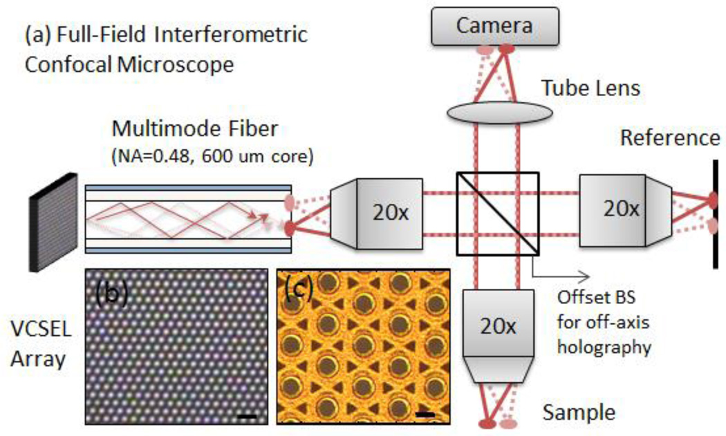
A schematic of the full-field confocal microscope is shown in Fig. 1. A microscope image of the VCSEL array (Princeton Optronics PCW-CE-4-W0808) is shown in Fig. 1(c) and an image of the array lasing is shown in Fig. 1(b). Each laser had a bandwidth of ~0.1 nm and the combined bandwidth of all 1200 lasers was ~1 nm. The lasers are each ~15 µm in diameter and periodically arranged in a 2D triangular array with a center-to-center spacing of ~44 µm. A step index multimode fiber with NA=0.48 and core diameter of 600 µm was used to collect the VCSEL array emission through a fiber collimator and deliver it to the microscope. Due to the relatively small divergence angle of the VCSEL array (~10°), the emission was easily collected with the multimode fiber. Each laser in the VCSEL array excited a different distribution of spatial modes in the fiber, resulting in distinct speckle patterns at the end of the multimode fiber. Since each of the ~1200 lasers are mutually incoherent, their speckle patterns are uncorrelated and add in intensity, providing a high power light source with low spatial coherence. Although multimode fibers can also reduce the spatial coherence of an individual laser if the temporal coherence is low [19], this effect is expected to be weak in our case due to the relatively narrow linewidth (~0.1 nm) of the individual lasers in the VCSEL array and the short length of the multimode fiber (1 meter). Nonetheless, the speckle contrast at the end of the fiber was reduced to N−1/2 where N is the number of uncorrelated speckle patterns. In this case, N~2×1200, where the factor of 2 accounts for each laser producing speckle patterns at the end of the fiber with orthogonal polarizations which do not interfere and add in intensity. The speckle contrast was therefore reduced to ~0.02, below the level of intensity variations humans can perceive [20].
Fig. 1.
(a) Schematic of the full-field confocal microscope. (b) A top-view of the VCSEL array while lasing—each dot is a separate laser. The scale bar is 100 µm. (c) Magnified view of the VCSEL array—each circle is an independent laser. The scale bar is 20 µm. The VCSEL array was coupled to a 1 meter long multimode fiber which scrambled the modes providing a uniform illumination source. The emission leaving the multimode fiber was imaged using 20× (NA=0.4) objectives onto the sample and reference arm through a beamsplitter. The beamsplitter was offset from the optical axis of the sample arm in order to introduce interference fringes in the detected signal. A CCD camera was then used to record the interference pattern.
The effective low spatial coherence of the VCSEL array can also be understood in comparison to the sources used, for example, in Ref. [14–16], which consisted of a conventional spatially coherent laser passed through a rotating diffuser. The rotating diffuser caused the speckle patterns illuminating the sample and reference to change over time. In those implementations, a relatively long integration time was then required to average over many diffuser positions, thereby reducing the speckle contrast and eliminating cross-talk in the detected interferometric signal. In our case, the 1200 lasers each produced a distinct speckle pattern, analogous to the speckle patterns produced by different diffuser positions. However, by using the VCSEL array, averaging over many speckle patterns was performed in parallel. We need only integrate longer than the temporal coherence of the modes (~10 ps based on the ~0.1 nm laser linewidth) to average out speckle. Thus, this approach has the potential for much faster imaging, and could also be used in applications which rely on very short integration times such as stroboscopic imaging [21] for which the rotating diffuser approach is particularly unsuited.
Although the VCSEL array could have been coupled directly into the microscope, the multimode fiber simplified the alignment and ensured spatially uniform illumination of the sample and reference arm. As shown in Fig. 1, the core of the multimode fiber was imaged through 20× objectives (NA=0.4) onto the reference and the sample arm. By placing a mirror on the reference arm, an image of the multimode fiber facet was produced on the charge coupled device (CCD) camera (Allied Vision Manta G-125) through a tube lens (f=15 cm). Light scattered by the sample was also imaged onto the CCD camera and the confocal signal was then encoded in the interference between the sample and reference arm. To enable single-shot detection without phase-stepping, we used an off-axis holography detection scheme. To do this, we offset the beamsplitter which introduced a phase tilt between the reference and sample arm images resulting in interference fringes.
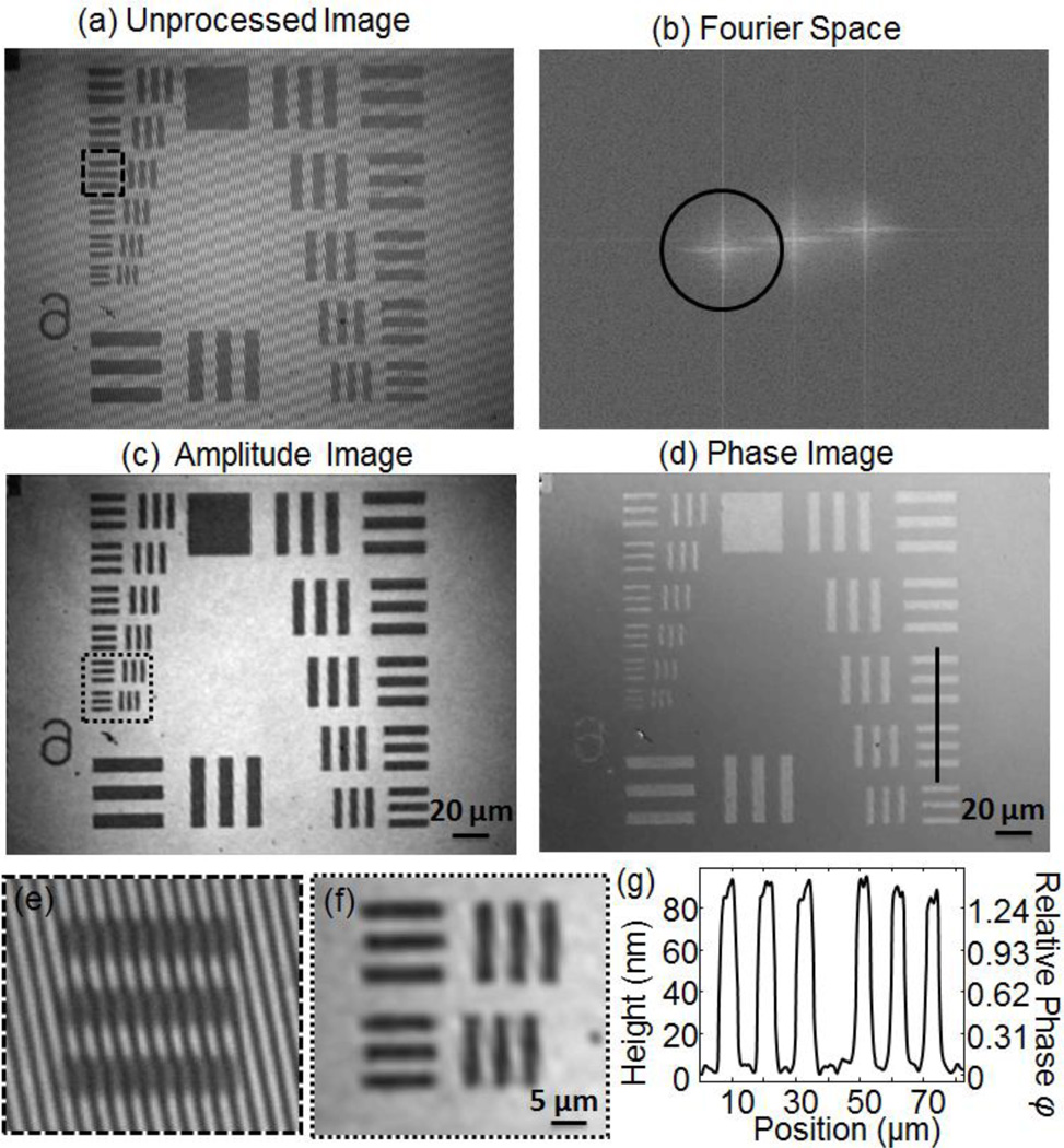
A typical unprocessed image recorded by placing a U.S. Air Force resolution target at the focal plane of the sample arm is shown in Fig. 2(a). A magnified view of the high contrast interference fringes are shown in Fig. 2(e). The confocal image was then extracted by applying a Hilbert filter in phase space. The spatial Fourier transform of the unprocessed image is shown in Fig. 2(b). We applied a Hann window to select the region of frequency space indicated by the red circle and moved this region to the center before applying an inverse Fourier transform. The amplitude and phase extracted from the inverse Fourier transform are shown in Fig. 2(c,d). As shown in Fig 2(f), the smallest features of the Air Force chart (2.19 µm lines) were clearly resolved.
Fig. 2.
(a) The unprocessed interference pattern measured on the CCD camera shown in Fig. 1. High contrast fringes are visible across the image. (b) The spatial Fourier transform of the image in (a). A Hann window indicated by the black circle was used to select the off-axis component. This component was then shifted back to the center of Fourier space. The amplitude (c) and phase (d) of the field from the sample is recovered after inverse Fourier transform of the filtered image in (b). (e) Magnified view of the region indicated in (a) showing high contrast interference fringes. (f) Magnified view of the region indicated in (c); features separated by 2.19 µm are clearly distinguishable. (g) The step height of the Air Force chart features extracted from the phase image along the cross section line shown in (d).
The high power per laser of the VCSEL array, combined with the low spatial coherence, which precluded the need for averaging over speckle patterns in time, enabled integration times as short as 100 µs, the minimum integration time on the camera. Even at such short integration times, the VCSEL array was attenuated to avoid saturating the camera. Thus, we expect this approach could enable high speed imaging of dynamic behavior with confocal resolution and sectioning. Moreover, the single shot image acquisition avoids the effect of motion artifacts and may be used for stroboscopic imaging by running the VCSEL array in pulsed mode.
In contrast to a standard scanning confocal microscope which records only the intensity, the interferometric confocal system presented here also records the phase of the field scattered by the sample. In the case of an Air Force chart, which consists of Chrome on glass, this phase information allows us to extract the step height, h, of the Air Force chart features as: h = φ[λ/(4π)], where λ is the illumination wavelength (808 nm) and φ is the relative phase difference between the Chrome and glass features of the phase image shown in Fig. 2(d). Note that what we measure is the phase of the field returning from the sample, and thus, to accurately extract the step height, we need to account for the phase delay introduced by reflections from different surfaces. In particular, the reflection from the air-Chrome interface introduces an additional phase delay of 0.32 radians compared with the reflection from the air-glass interface, due to the complex index of refraction of Chrome (n~3.18+3i at λ=808 nm). After accounting for this factor, the step height of the Air Force chart can be accurately measured. In Fig. 2(g), we show the extracted step height measured across the group 6 features of the Air Force chart, indicating an 80 nm step. This step height was confirmed using a mechanical profilometer (Alpha-Step IQ Surface Profiler).
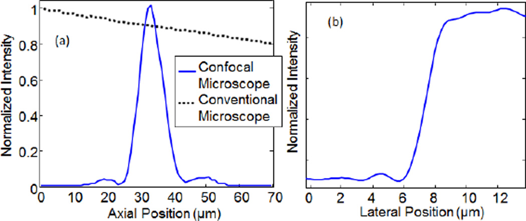
As in confocal systems using a physical pinhole, the interferometric confocal system shown here provides optical sectioning. To measure the axial point spread function, we plasced a mirror in the sample arm and scanned its position through the focal plane of the objective and recorded the intensity of the confocal image. As shown in Fig. 3, the interferometric confocal system shows a sharp axial response with full-width at half-maximum (FWHM) of ~ 8 µm. Based on the 0.4 NA of the microscope objectives, we would expect the FWHM axial point spread function to be ~1.26λ/NA2 = 6.3 µm [1]. The slight degradation in the observed axial resolution is a result of imposing the off-axis interference fringes by offsetting the beamsplitter. This had the secondary effect of under-filling the back aperture of the objective, thereby reducing the effective NA. Based on the observed axial PSF, the effective NA is ~0.36. The full-resolution of the objectives could be achieved by phase-stepping on the reference arm, rather than using an off-axis holography approach to recover the sample field. Alternately, adding a diffraction grating to one arm could be used to introduce high spatial frequency fringes without sacrificing resolution while maintaining single-shot image acquisition [16, 22]. We also repeated this experiment while blocking the sample arm to provide a comparison with a conventional, non-interferometric wide-field microscope. Although the conventional microscope image blurs with de-focus, the total intensity recorded as the mirror is scanned through the focal plane remains relatively constant.
Fig. 3.
(a) The axial point spread function (PSF) was recorded by scanning a mirror through the focal plane and recording the intensity of the confocal image as a function of mirror position. The confocal microscope shows a sharp axial response with FWHM ~ 8 µm, compared to the conventional microscope in which the recorded intensity decays slowly with defocus. (b) The lateral PSF was estimated by examining the sharpness of the edge in the image of the resolution chart shown in Fig. 2(c). The half-width-half-max is ~1.2 µm.
We also estimated the lateral resolution by examining the image intensity across the edge of the features in the AF chart shown in Fig. 2(c). As shown in Fig. 3(b), the intensity showed a sharp increase across the feature edge with a half-width-half-max of ~1.2 µm. In the current implementation, the lateral resolution was limited by the off-axis holography approach and could be improved to reach the diffraction limit of the microscope objectives (0.88λ/(2NA) ~ 0.9 µm [1]) by phase stepping on the reference arm. The lateral resolution of the microscope also dictates the effective speckle size on the sample and hence the virtual pinhole size. The total number of virtual pinholes is then given by the field of view divided by the effective speckle size (i.e. a circle with radius ~1 µm). Since the field of view of the image was 210×280 µm, we were able to acquire en face confocal images with the equivalent of ~18,000 virtual pinholes in parallel. Note that the number of virtual pinholes is not limited to the 1200 lasers in the VCSEL array, since these lasers are used to eliminate cross-talk through averaging, rather than as independent imaging channels. This dramatically reduces the required source complexity (i.e. the number of lasers in the array) while allowing massively parallel full-field imaging. In general, we expect the number of virtual pinholes to be limited by the number of resolvable elements provided by the microscope objective, whereas the number of lasers required to eliminate cross-talk will depend on the degree of scattering in the sample, the required speckle suppression, as well as aberrations in the imaging system. Moreover, the parallel cross-talk suppression provided by the VCSEL array could be combined with temporal averaging over different speckle patterns (introduced by a rotating diffuser or simply by shaking the multimode fiber to change the mode coupling conditions). This could enable averaging over many more speckle patterns to further suppress cross-talk at the cost of increased integration time.
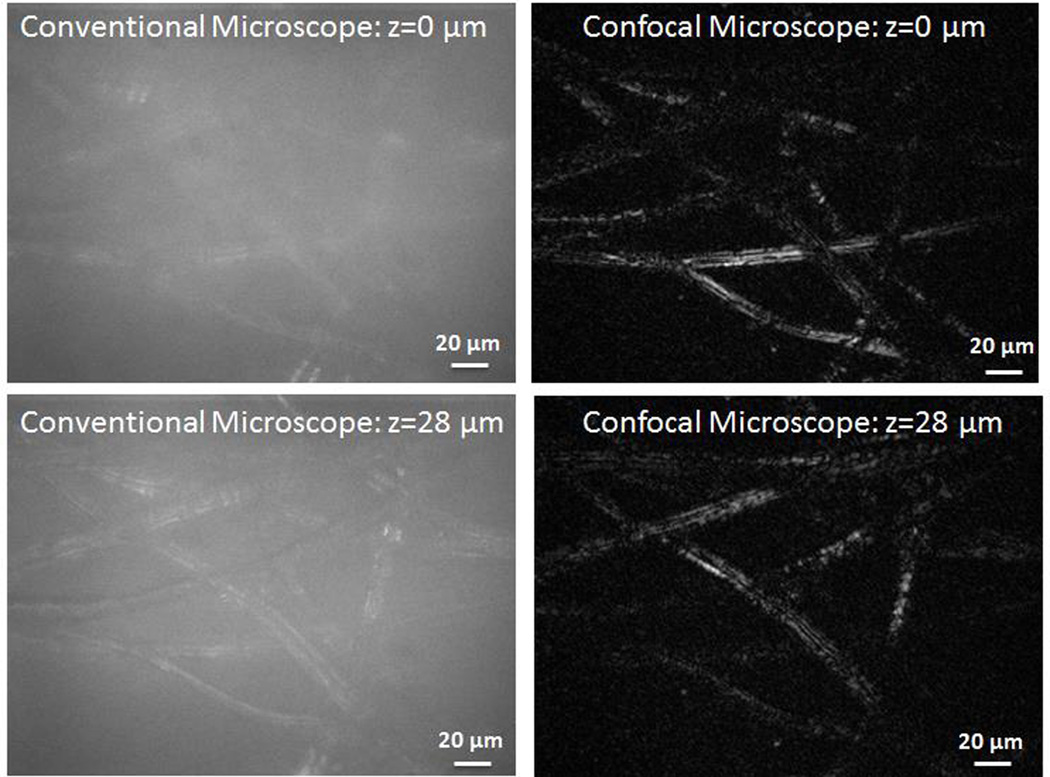
To demonstrate the optical sectioning capabilities of the confocal microscope, we recorded a series of images at different planes by scanning a piece of lens paper across the focal plane. The lens paper consists of a three-dimensional structure of threads. In Fig. 4, we show images recorded at two different planes with the confocal microscope along with images taken with a conventional wide-field microscope (i.e with the reference arm blocked). In the confocal images, the threads of the lens paper in the focal plane are clearly visible while scattered light from out-of-plane threads is rejected. However, in the conventional microscope image, the contribution from out-of-plane threads introduces a strong blurry background which reduces the image contrast. A movie showing 40 frames collected as the lens paper was scanned across the focal plane is provided in Media 1.
Fig. 4.
Images of lens paper at two focal planes separated by 28 µm. The conventional microscope images were recorded by blocking the reference arm. Unlike the conventional microscope, the optical sectioning ability of the confocal microscope enables imaging of different planes while rejecting out of plane light. (Multimedia online) Supplementary video shows the conventional microscope and confocal images as the lens paper is scanned through the focal plane.
In summary, we demonstrated a full-field, interferometric confocal microscope using spatial coherence gating to acquire single-shot en face images. Illumination was provided by a VCSEL array which combined high power per mode with low spatial coherence, enabling high-speed parallel image acquisition. The confocal system collected 210×280 µm field of view images with ~2 µm lateral and ~8 µm axial resolution at integration times as short as 100 µs. The same system could be adapted to provide higher resolution imaging using higher NA microscope objectives. In addition, interferometric detection provides access to phase information enabling quantitative phase measurements, enhanced contrast imaging of phase objects, or Doppler flow measurements.
Supplementary Material
Acknowledgments
This work was supported by the National Science Foundation under Grant No. ECCS-1128542 and the National Institute of Health under Grant No. 1R21EB016163-01A1.
References
- 1.Webb RH. Confocal optical microscopy. Reports Prog. Phys. 1996;59:427–471. [Google Scholar]
- 2.Kino GS, Corle TR. Confocal scanning optical microscopy and related imaging systems. Academic Press; 1996. [Google Scholar]
- 3.Rajadhyaksha M, Anderson RR, Webb RH. Video-rate confocal scanning laser microscope for imaging human tissues in vivo. Appl. Opt. 1999;38:2105–2115. doi: 10.1364/ao.38.002105. [DOI] [PubMed] [Google Scholar]
- 4.Liu JTC, Mandella MJ, Ra H, Wong LK, Solgaard O, Kino GS, Piyawattanametha W, Contag CH, Wang TD. Miniature near-infrared dual-axes confocal microscope utilizing a two-dimensional microelectromechanical systems scanner. Opt. Lett. 2007;32:256–258. doi: 10.1364/ol.32.000256. [DOI] [PMC free article] [PubMed] [Google Scholar]
- 5.Petráň M, Hadravský M, Egger MD, Galambos R. Tandem-Scanning Reflected-Light Microscope. J. Opt. Soc. Am. 1968;58:661. [Google Scholar]
- 6.Egner A, Andresen V, Hell SW. Comparison of the axial resolution of practical Nipkow-disk confocal fluorescence microscopy with that of multifocal multiphoton microscopy: theory and experiment. J. Microsc. 2002;206:24–32. doi: 10.1046/j.1365-2818.2002.01001.x. [DOI] [PubMed] [Google Scholar]
- 7.Shimozawa T, Yamagata K, Kondo T, Hayashi S, Shitamukai A, Konno D, Matsuzaki F, Takayama J, Onami S, et al. Improving spinning disk confocal microscopy by preventing pinhole cross-talk for intravital imaging. Proc. Natl. Acad. Sci. 2013;110:3399–3404. doi: 10.1073/pnas.1216696110. [DOI] [PMC free article] [PubMed] [Google Scholar]
- 8.Dwyer PJ, DiMarzio CA, Rajadhyaksha M. Confocal theta line-scanning microscope for imaging human tissues. Appl. Opt. 2007;46:1843–1851. doi: 10.1364/ao.46.001843. [DOI] [PubMed] [Google Scholar]
- 9.Larson B, Abeytunge S, Rajadhyaksha M. Performance of full-pupil line-scanning reflectance confocal microscopy in human skin and oral mucosa in vivo. Biomed. Opt. Express. 2011;2:2055–2067. doi: 10.1364/BOE.2.002055. [DOI] [PMC free article] [PubMed] [Google Scholar]
- 10.Im K-B, Han S, Park H, Kim D, Kim B-M. Simple high-speed confocal line-scanning microscope. Opt. Express. 2005;13:5151–5156. doi: 10.1364/opex.13.005151. [DOI] [PubMed] [Google Scholar]
- 11.Wang D, Chen Y, Wang Y, Liu JTC. Comparison of line-scanned and point-scanned dual-axis confocal microscope performance. Opt. Lett. 2013;38:5280–5283. doi: 10.1364/OL.38.005280. [DOI] [PMC free article] [PubMed] [Google Scholar]
- 12.Tearney GJ, Webb RH, Bouma BE. Spectrally encoded confocal microscopy. Opt. Lett. 1998;23:1152–1154. doi: 10.1364/ol.23.001152. [DOI] [PubMed] [Google Scholar]
- 13.Safrani A, Abdulhalim I. Ultrahigh-resolution full-field optical coherence tomography using spatial coherence gating and quasi-monochromatic illumination. Opt. Lett. 2012;37:458–460. doi: 10.1364/OL.37.000458. [DOI] [PubMed] [Google Scholar]
- 14.Somekh MG, See CW, Goh J. Wide field amplitude and phase confocal microscope with speckle illumination. Opt. Commun. 2000;174:75–80. [Google Scholar]
- 15.Pitter MC, See CW, Somekh MG. Full-field heterodyne interference microscope with spatially incoherent illumination. Opt. Lett. 2004;29:1200–1202. doi: 10.1364/ol.29.001200. [DOI] [PubMed] [Google Scholar]
- 16.Choi Y, Yang TD, Lee KJ, Choi W. Full-field and single-shot quantitative phase microscopy using dynamic speckle illumination. Opt. Lett. 2011;36:2465–2467. doi: 10.1364/OL.36.002465. [DOI] [PubMed] [Google Scholar]
- 17.Dubois A, Vabre L, Boccara A-C, Beaurepaire E. High-resolution full-field optical coherence tomography with a Linnik microscope. Appl. Opt. 2002;41:805–812. doi: 10.1364/ao.41.000805. [DOI] [PubMed] [Google Scholar]
- 18.Seurin J-F, Xu G, Khalfin V, Miglo A, Wynn JD, Pradhan P, Ghosh CL, D’Asaro LA. Progress in high-power high-efficiency VCSEL arrays. Proc. SPIE. 2009;7229:722903. [Google Scholar]
- 19.Dhalla A-H, Migacz JV, Izatt JA. Crosstalk rejection in parallel optical coherence tomography using spatially incoherent illumination with partially coherent sources. Opt. Lett. 2010;35:2305–2307. doi: 10.1364/OL.35.002305. [DOI] [PubMed] [Google Scholar]
- 20.Wang L, Tschudi T, Halldórsson T, Pétursson PR. Speckle reduction in laser projection systems by diffractive optical elements. Appl. Opt. 1998;37:1770–1775. doi: 10.1364/ao.37.001770. [DOI] [PubMed] [Google Scholar]
- 21.Mermillod-Blondin A, Mentzel H, Rosenfeld A. Time-resolved microscopy with random lasers. Opt. Lett. 2013;38:4112–4115. doi: 10.1364/OL.38.004112. [DOI] [PubMed] [Google Scholar]
- 22.Ikeda T, Popescu G, Dasari RR, Feld MS. Hilbert phase microscopy for investigating fast dynamics in transparent systems. Opt. Lett. 2005;30:1165–1167. doi: 10.1364/ol.30.001165. [DOI] [PubMed] [Google Scholar]
Associated Data
This section collects any data citations, data availability statements, or supplementary materials included in this article.


