

Abstract
Background and Aims
Windstorms are the major natural hazard affecting European forests, causing tree damage and timber losses. Modelling tree anchorage mechanisms has progressed with advances in plant architectural modelling, but it is still limited in terms of estimation of anchorage strength. This paper aims to provide a new model for root anchorage, including the successive breakage of roots during uprooting.
Methods
The model was based on the finite element method. The breakage of individual roots was taken into account using a failure law derived from previous work carried out on fibre metal laminates. Soil mechanical plasticity was considered using the Mohr–Coulomb failure criterion. The mechanical model for roots was implemented in the numerical code ABAQUS using beam elements embedded in a soil block meshed with 3-D solid elements. The model was tested by simulating tree-pulling experiments previously carried out on a tree of Pinus pinaster (maritime pine). Soil mechanical parameters were obtained from laboratory tests. Root system architecture was digitized and imported into ABAQUS while root material properties were estimated from the literature.
Key Results
Numerical simulations of tree-pulling tests exhibited realistic successive root breakages during uprooting, which could be seen in the resulting response curves. Broken roots could be visually located within the root system at any stage of the simulations. The model allowed estimation of anchorage strength in terms of the critical turning moment and accumulated energy, which were in good agreement with in situ measurements.
Conclusions
This study provides the first model of tree anchorage strength for P. pinaster derived from the mechanical strength of individual roots. The generic nature of the model permits its further application to other tree species and soil conditions.
Keywords: Tree anchorage, root mechanical properties, soil mechanical strength, failure modelling, functional–structural plant modelling, finite element method, ABAQUS, coarse root architecture, windthrow, Pinus pinaster, maritime pine
INTRODUCTION
Windstorms are among the primary causes of destruction in forests (Gandhi et al., 2008; McCarthy et al., 2010). In particular, they are the major hazard affecting European forests, causing tree and timber losses. Moreover, reported wind-induced damage in Europe has increased since the last century due to forest expansion (Gardiner et al., 2010). The increasing stock and average age of European forests and the observed ongoing climate changes, with the prediction of stronger windstorms (Della-Marta and Pinto, 2009), may also lead to a growing wind risk. For instance, storm Klaus, which hit southern Europe in January 2009, resulted in an estimated 43 000 000 m3 of timber being blown down in southwest France, including a volume of 37 000 000 m3 for Pinus pinaster (GPMF, 2011).
Numerous efforts have been made to model forest damage caused by wind (Gardiner et al., 2008). They have led to several predictive models for forest damage (overturning, stem breakage), i.e. HWIND, GALES and FOREOLE (Peltola et al., 1999; Gardiner et al., 2000; Ancelin et al., 2004). These models included empirical relationships to determine the tree's resistance to overturning based on tree-pulling tests. They are therefore are limited to the site conditions for which they were built (GALES and FOREOLE). Moreover, the resistance to overturning predicted by these empirical relationships used rough and simplified parameterization (HWIND).
Tree anchorage capacities vary with time and result from complex interactions between growing roots and their physical and biological environment. Previous observations and experimental studies have reported that part of root architecture plasticity is due to biomechanical acclimation when trees are subjected to wind loads (Stokes et al., 1995; Nicoll and Ray, 1996; Coutts et al., 1999; Tamasi et al., 2005; Lundström et al., 2007; Nicoll et al., 2008; Danjon et al., 2013). In particular, biomechanical acclimation of trees has been proved in the case of adult P. pinaster trees, for which asymmetrical patterns can play an important mechanical role in tree anchorage (Danjon et al., 2005). In the context of global change it is very important for wind risk prediction models to take into account the ability of trees to develop stronger anchorage with specific root traits as a biomechanical response to the wind. We therefore have to provide a tool capable of predicting tree stability by taking into account the acclimation of root systems and changes in soil strength as a function of climate conditions. This requires progress in understanding the uprooting process as a function of tree characteristics and soil material properties. The first studies on tree uprooting mechanisms were based on the experimental work of Coutts (1983, 1986), who also developed the first systematic method of analysing tree anchorage (Coutts, 1986). This author quantified the relative impacts of different anchorage components on Sitka spruce, i.e. root–soil weight, root material strength under tension and soil strength, on the overturning resistance of spruce. This method led to the first mechanistic model of tree anchorage (Blackwell et al., 1990) that described the root anchorage strength in terms of these components. Understanding of the anchorage mechanism progressed with the use of numerical analysis and advances in plant architecture digitizing (Dupuy et al., 2005b, 2007; Fourcaud et al., 2008). This approach used the finite element method (FEM) to calculate the deformation of root–soil systems in three dimensions. Real and simulated root systems with their specific architectural properties were considered in the simulations. These analyses allowed comparison of the theoretical anchorage performances of different root types, i.e. tap-, herringbone-, heart- and plate-like root systems, in clay and sandy soils. In addition, Fourcaud et al. (2008) attempted to quantify the relative roles of root components, e.g. superficial laterals, deep roots and tap roots, in anchorage strength in different soil types using a simple 2-D FEM model. Rahardjo et al. (2009) developed a finite element model of root anchorage and used a parametric study to examine the influence of soil properties. Thus, numerical models have been used essentially to investigate the influence of root architecture on tree anchorage using theoretical parameters for soil and roots. Less is known about the failure mechanism, which is crucial for predicting the occurrence of uprooting. This implies to better understand the effect of soil–root friction, root strength and soil strength on the whole response of root systems involved in the overturning process.
Our paper has two objectives. Firstly it presents a new model of tree anchorage that simulates the root breakage mechanism during tree uprooting, and secondly it tests this model in comparison with a field experiment in the case of young P. pinaster, which has simpler root architecture than adult specimens. In the first section we present the basis of the model and the tree-pulling tests performed in the field. In the second section, we analyse the simulated response of the whole root system and compare it with measurements, and in the last section we discuss the model's capacity to simulate uprooting.
MATERIALS AND METHODS
Anchorage model
The FEM model presented here is based on the initial work by Dupuy et al. (2007) and uses the ABAQUS software, version 6.13 (http://www.3ds.com/products-services/simulia/portfolio/Abaqus/). The model is composed of three parts: (1) the parallelepiped soil domain; (2) the root system; and (3) a perfectly rigid stem used as a lever arm to mimic tree uprooting (Fig. 1). All relevant details not given here can be found in Dupuy et al. (2007). The vertical rigid stem was tied to the top of the stump of the root system; therefore, the stem base and the top of the stump always had the same displacement. The 3-D root architecture was modelled as an assemblage of discretized beams with a defined topology, branching pattern and geometry. It was imported in ABAQUS from the software Xplo (http://amapstudio.cirad.fr/soft/xplo/start; Griffon and de Coligny, 2013) dedicated to the encoding and visualization of plant architectures.
Fig. 1.
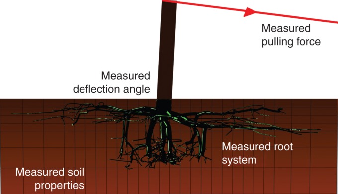
Anchorage model with root system architecture and soil properties measured for tree-pulling simulations. Model outputs are the response curve of turning moment versus the deflection angle at the stem base and the total energy supplied by the pulling force. Deflection angle is defined as the angle between the vertical and the stem.
In this new model, the developments were focused on root–soil interaction, the mechanical behaviour of root material and the characteristics of the soil. Due to the complexity of meshing root architecture with 3-D solid elements, the roots were considered as embedded beam elements. We evaluated the relevance of this choice in a preliminary study carried out on a 3-D direct shear test of a soil block with root inclusions. Simulations considering roots modelled with embedded beam elements were compared with simulations using 3-D solid elements and root–soil interface friction properties (see Appendix). This study concluded that (1) the embedded beam elements mimicked the friction behaviour at the root–soil interface with a friction coefficient of ∼0·1; and (2) for friction coefficients ranging from 0·1 to 0·9, the relative difference between the two approaches was always <21 % during the entire shear process. Embedded beam elements were then used in the anchorage model, implying that all the roots were slender structures embedded in the soil region. The roots were meshed with 3-D two-node linear Timoshenko beam elements with circular cross-sections (B31 in the ABAQUS element library).
The anchorage model described above allows the tree anchorage behaviour of various tree species to be modelled under different soil conditions. In our study, we chose a specific case of P. pinaster planted in sandy soil. The inputs of the model were: (1) a digitized root system of P. pinaster excavated after an in situ tree-pulling experiment; (2) soil properties from soil measurements in the laboratory; (3) root material properties from data taken from the literature, as described in the following sections. The model outputs were expressed by using response curves, i.e. ‘turning moment’ versus ‘deflection angle at the stem base’ and the energy supplied to the system during uprooting.
Formalism of individual root rupture
In the previous modelling work of Dupuy et al. (2007), the roots could only yield in the same way as metals, which exhibit plastic-like yielding, and the stresses remained stored in the roots after reaching the plasticity criterion. However, the roots were expected to exhibit brittle behaviour in tension, with their cumulated stress released and redistributed to the remaining roots during the uprooting process. Such features have been repeatedly observed and modelled when considering soil reinforcement by fine roots with diameter generally <1 cm (Abernethy and Rutherfurd, 2001; Pollen and Simon, 2005; Pollen, 2007). Therefore, roots were modelled as brittle material in the present root anchorage model. An elastic failure law based on continuum damage mechanics was developed for roots under tension, compression and bending, based on previous constitutive laws regarding fibre metal laminates (Linde et al., 2004). The law described by Linde et al. (2004) was adapted for wood beam elements and implemented in ABAQUS through the UMAT user subroutine.
In this model, roots are elastic in their initial state. During incremental loading, the damage initiation criterion is evaluated at each material point in every beam cross-section to detect the onset of damage. If the damage initiation criterion is reached, root stiffness degradation can be derived from the damage evolution law. The linear elastic behaviour defined in the beam cross-section axis is given by:
| (1) |
and
| (2) |
where σel11, τel11 and τel21 represent the beam's elastic axial stress component and two elastic shear stress components along two perpendicular directions in the cross-section, respectively; Er and Gr are modulus of elasticity and shear modulus, respectively; [C] is the non-degraded root stiffness tensor in its matrix form; and εel11, γel21 and γel31 represent the axial strain component and two shear strain components, respectively. The damage initiation criterion f is defined in terms of ultimate tensile strain εt11, ultimate compressive strain εc11 and actual strain ε11. Damage onset occurs when fulfilling the criterion:
| (3) |
where
| (4) |
| (5) |
σt11 and σc11 being the tensile strength and compressive strength of the root material, respectively, and f is zero for axial strain ε11 ranging from 0 to εt11 – εc11. Beyond this small interval it increases with increasing axial strain in both tensile and compressive directions. Figure 2A gives an example of the behaviour of f – εt11 (using data SA5, Table 3). As long as the damage initiation criterion is reached, the damage variable d is defined as the damage evolution law:
| (6) |
where Lc in our case is the characteristic length of the beam element and Gf is the fracture energy of the root material. The damage variable d is valid and takes continuous values from 0 to 1 from the axial failure strains defined by f in the compressive and tensile directions. Figure 2B gives an example of the behaviour of d in the tensile direction (data set SA5 of Table 3). The damage variable d increases abruptly, which means our constitutive law models root brittleness correctly. Finally, stiffness degradation in the root material is modelled by including the damage variable in the stiffness matrix as follows:
| (7) |
This shows that, after reaching the damage initiation criterion, the evolution of d causes the stiffness in the root material to decrease progressively. In our case, convergence difficulties occurred during calculations due to the complex geometry (the multi-branched root system) and large deformations. Thus, viscous regularization is applied to the damage variable d to improve convergence, and the regularized damage variable dv is used in the program instead of d:
| (8) |
where η is the viscosity parameter controlling the rate at which dv approaches the true damage variable d. The value of η is assumed to be small compared with the size of the increment to satisfy the assumption of quasi-brittle material.
Fig. 2.
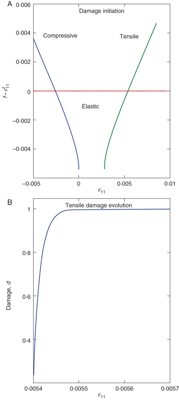
Root failure behaviour described by the constitutive law. (A) Damage initiation criterion f – εt11 compared with 0; green curve above 0 (red horizontal line) means damage initiation in the tensile direction, blue curve above 0 means damage initiation in the compressive direction and both below 0 means an elastic state. (B) Damage (d) developed in the tensile axial direction.
Table 3.
Root data sets for five simulations (SA1–SA5) using the 3-D anchorage model
| Unit | Root diameter interval | SA1 | SA2 | SA3 | SA4 | SA5 | SA6 | SA7 | |
|---|---|---|---|---|---|---|---|---|---|
| Er | GPa | <1 cm | 7·2 | 8·3 | 6·1 | 6·4 | 8 | 8 | 8 |
| 1–6 cm | 7·2–8·8 | 8·3–10·1 | 6·1–7·5 | 6·4–9·6 | 8 | 8 | 8 | ||
| >6 cm | 8·8 | 10·1 | 7·5 | 9·6 | 8 | 8 | 8 | ||
| ρr | kg m–3 | <1 cm | 379·3 | 421·4 | 337·2 | 337·2 | 421·4 | 421·4 | 421·4 |
| 1–6 cm | 379·3–463·6 | 421·4–515·0 | 337·2–412·2 | 337·2–505·7 | 421·4 | 421·4 | 421·4 | ||
| >6 cm | 463·6 | 515·0 | 412·2 | 505·7 | 421·4 | 421·4 | 421·4 | ||
| σt11 | MPa | <1cm | 38·8 | 44·3 | 33·4 | 34·5 | 43·2 | 43·2 | |
| 1–6 cm | 38·8–47·5 | 44·3–54·1 | 33·4–40·8 | 34·5–51·8 | 43·2 | 43·2 | |||
| >6 cm | 47·5 | 21·1 | 40·8 | 51·8 | 43·2 | 43·2 | |||
| σc11 | MPa | <1 cm | 18·6 | 21·1 | 16·0 | 16·5 | 20·6 | ||
| 1–6 cm | 18·6–22·7 | 21·1–25·8 | 16·0–19·6 | 16·5–24·8 | 20·6 | ||||
| >6 cm | 22·7 | 25·8 | 19·6 | 24·8 | 20·6 |
Verification of the model for individual root failure
Before applying the constitutive law to the whole root system, it is necessary to test whether it reproduces the brittle rupture of the root material; rupture is expected to occur at the strength limits (σt11 or σc11) with a sharp decrease in stress after failure. Tensile, compressive and bending tests were performed numerically in ABAQUS on a cantilever beam 1 m in length and 0·04 m in diameter, with a characteristic length (Lc = 0·1 m) and the root material properties for SA5 given in Table 3. Displacement was separately imposed at the free end of the beam in the tensile direction, the compressive direction and perpendicular to the axial direction (Fig. 3A). Panels 1, 2 and 3 in Fig. 3 show the force-displacement curves obtained at the free tip of the beam during calculations for tensile, compressive and bending simulation tests, respectively. Figure 3B4 illustrates the numerical effect due to the viscous regularization parameter η. Panels 1 and 2 in Fig. 3B show that the root tensile and compressive strength predicted by tests agree well with the input (σt11 and σc11). Root compressive behaviour is as brittle as that in tension and the root fails in compression at a lower axial strain, while the degradation of bending strength and stiffness is more gradual (Fig. 3B3). Parameter η for viscous regularization was calibrated by beam tensile tests with five different η values ranging from 0·00001 to 0·1, compared with the increment of 0·02 (Fig. 3B4). The three smaller η values (0·00001, 0·0001 and 0·001) predict curve behaviour similar to that without viscous regularization. However, the results from larger η values (0·01 and 0·1) predict less brittle tensile behaviour and overestimate the tensile strength of the root specimen. Thus, small η values compared with the characteristic size of increments should be used to avoid numerical discrepancies when modelling root mechanical behaviour. In the following, simulations hold for η = 0·000075.
Fig. 3.
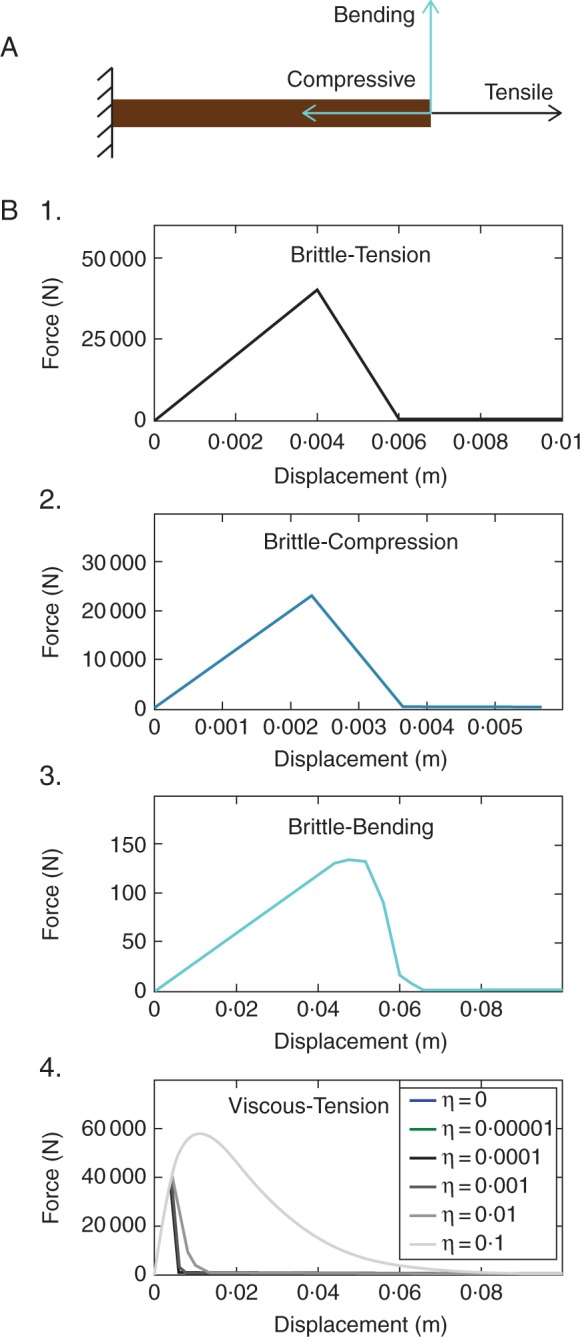
Numerical root failure behaviour tests and results. (A) A cantilever beam of wood material subjected to different displacements at the free end: tensile, compressive and bending tests. (B) Force–displacement curves predicted by simulations at the free end: 1, tensile test; 2, compressive test; 3, bending test; 4, tensile tests including viscous effect (η values are 0·0, 1·0e–5, 1·0e–4, 1·0e–3, 1·0e–2 and 1·0e–1).
Field experiment and parameter measurements
Site and tree-pulling experiment
A tree-pulling experiment was carried out on 24 April 2012 on a selected 13-year-old P. pinaster tree 0·18 m in diameter at breast height (Nézer forest in the southwest of France, altitude 15 m, latitude 44·6/44° 36′0″ N, longitude –1·03333/1° 1′60″ W; la Mairie du Teich). In 2012 the site had a total yearly rainfall of 846·7 mm and a mean temperature of 9·2°C (Météo France). The pulling direction was perpendicular to the prevailing wind direction (northwest). The experimental protocol was similar to that used by Nicoll et al. (2006) and many others (Coutts, 1986; Moore, 2000; Cucchi et al., 2004; Kamimura et al., 2012). The selected tree was overturned with a motorized winch (WinchMax 7550, 5681 kg; Winchmax, UK; http://www.winchmax.co.uk/). The cable was attached to the stem of the pulled tree at the height of 1·68 m. The winch was attached to the stem base of an anchor tree at a distance of ≃12 m from the pulled tree so that the pulling force can be considered horizontal with an error of 1 %. The part of the tree above this height was cut off. The pulling force was measured by a load cell (SM 5420, 50 kN; Sensel, France) and the stem deflection angles on the top and at the base of the stem were measured by two inclinometers (SN: 25276; Sensel, France). The turning moment was calculated using the horizontal component of the pulling force.
Root architecture
Root system excavation, measurements and modelling were performed according to Danjon et al. (1999, 2005). On 15 May 2012 the soil surrounding the damaged root system was removed with a high-pressure soil pick (Soil Pick; MBW Inc., USA; http://www.mbw.com/products/Pick.aspx) and the root system was excavated with a large mechanical shovel. Roots thinner than 1 cm in basal diameter were removed before the measurements. Root breakages were marked and large root deformations corrected manually, in order to return as close as possible to the undamaged state of the root system. In the meantime, the root system was discretized by a Polhemus Fastrak low magnetic field digitizer (Polhemus, Colchester, VT, USA; http://www.polhemus.com) and encoded in a standard format (MTG) commonly used for representing branching topological relationships at different observation scales (Godin and Caraglio, 1998). The MTG file was then read by Xplo software and exported to the root anchorage model in a format readable by ABAQUS.
Soil mechanical parameters
Around the pulled tree, soil was sampled at four locations in the main cardinal directions at depths of 0–10, 10–30 and 30–60 cm, just above water table level (≃60 cm depth) to measure soil bulk density and water content and to collect material for the mechanical tests. Then, 12 sandy soil samples were reconstituted with an initial dry bulk density of 1410 kg m–3 and an initial gravimetric water content of 0·11 g g–1, both corresponding to the mean values measured in the field. Direct shear tests were conducted using a Wykeham Farrance shear testing machine to characterize soil mechanical properties. The soil material was assumed to be initially linear elastic (defined by modulus of elasticity Es), combined with plastic behaviour modelled using the Mohr–Coulomb failure criterion available in the ABAQUS materials library (Table 1):
| (9) |
where τmax is soil shear strength, σn the normal pressure in the soil failure plane, ϕ the soil internal friction angle and c the soil cohesion (Bardet, 1997).
Table 1.
Measurements of mechanical properties of soil material: elastic–plastic with the Mohr–Coulomb criterion
| Symbol | Value | Unit | |
|---|---|---|---|
| Density | ρs | 1410 | kg m–3 |
| Modulus of elasticity | Es | 19·86 | MPa |
| Poisson's ratio | ν | 0·33 | – |
| Cohesion | c | 21·402 | kPa |
| Friction angle | ν | 14·62 | ° |
| Dilation angle | ψ | 0 | ° |
Simulation set-up
Simulations were performed to mimic the field experiment. The stem height at which the pulling force was applied was 1·68 m. The soil domain (dimensions 8 m × 8 m × 4 m) was meshed with eight-node linear brick elements with reduced integration (C3D8R in the ABAQUS element library), with the region containing the roots meshed into finer elements with an approximate edge size of 0·25 m. Symmetrical boundary conditions (XSYMM and YSYMM in the ABAQUS Analysis User's Guide) were imposed on the four laterals of the soil domain so that these faces were blocked to constrain soil motions with respect to the planes considered (x, z and y, z). The boundary condition of fully built-in (ENCASTRE in the ABAQUS Analysis User's Guide) was defined for the bottom of the soil to block all six degrees of freedom in the x, y plane. The root architecture measured was imported into ABAQUS as already explained. Loading was applied on the root–soil system in two steps: the gravity body force was applied first with gravity constant g = 9·81 m s−2, then a horizontal displacement of 1·2 m was imposed in the direction of the x axis at the top of the stem to ensure a maximum deflection angle of 45°. This displacement implies large deformations in the root–soil system, which makes sure that maximum turning moment occurs largely before the end of the simulation. The reaction force and corresponding displacement at the top of the stem were recorded during the simulation. The force–displacement response curves were analysed by calculating the work done by the pulling force as the integral of pulling force F as a function of the maximum horizontal displacement, d0, imposed on the top of the stem:
| (10) |
with x the horizontal displacement. The 3-D anchorage model requires a set of root parameters, namely ρr (root density), Er, σt11, σc11 and Gf, to characterize root mechanical behaviour. The relationships among these parameters were developed using recent evidence for stem wood of pine species and roots of P. pinaster reported in the literature (Stokes and Mattheck, 1996; Stokes et al., 1997; Khuder et al., 2007; Niklas and Spatz, 2010; Kretschmann, 2010). Niklas and Spatz (2010) showed that the modulus of elasticity Er was linearly correlated to root density ρr, tensile strength σt11 and compressive strength σc11 for the stem wood of more than 100 worldwide species. Here data for green wood samples of 16 pine species (Kretschmann, 2010) were used to obtain these relationships (Table 2). Values of ρr and Er were found to decrease with increasing distance from the tree stem in the lateral roots of P. pinaster (Khuder et al., 2007). Thus, considering that the diameter decreases with increasing distance, ρr and Er were assumed to be positively linearly correlated to root diameter. Er was fixed at 8 GPa for a root diameter of 3·5 cm in the first simulation, SA1 (range taken from data source: Stokes et al., 1997; Khuder et al., 2007). A linear variation in Er from 7·2 to 8·8 GPa was defined for SA1 for root diameters ranging from 1 to 6 cm (Fig. 4). The value of Er for roots of diameter <1 and >6 cm was fixed at constant values equal to 7·2 and 8·8 GPa, respectively (Fig. 4). Then all the other mechanical parameters related to Er were determined using relationships in Table 2. The fracture energy Gf was fixed at a value found in the literature (Dourado et al., 2008), i.e. 209·4 J m−2 for the stem wood of P. pinaster for all the simulation cases. To take into account variety in mechanical properties and variety in relationships between mechanical and geometric properties (i.e. root diameter in our study), four other simulation cases were defined in the same way with (1) different Er central values for roots of diameter 3·5 cm (9·2 and 6·8 GPa in SA2 and SA3, respectively; Fig. 4); and (2) different variations in Er for the range of root diameters (1 and 6 cm) (± 20 % and ± 0 % with respect to the central value in SA4 and SA5, respectively; Fig. 4).
Table 2.
Linear correlations between Er (in GPa) and {ρr, σt11, ρr} for green wood of 16 pine species
| Correlation | Unit | R² | |
|---|---|---|---|
| ρr | 38·94 Er + 109·91 | kg m–3 | 0·641 |
| σt11 | 5·07 Er + 2·61 | MPa | 0·577 |
| σc11 | 2·37 Er + 1·69 | MPa | 0·633 |
Fig. 4.
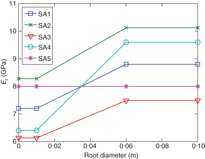
Linear relationships of modulus of elasticity of root material (Er) versus root diameter applied to the entire root system for five simulation cases (SA1–SA5). More detailed information about parameter values in each case is presented in Table 3.
Two other simulations, SA6 and SA7, without root failure behaviour were also performed in comparison with the previous five simulations and the experiment. Simulation SA6 defines elastic behaviour for all roots with Er of 8 GPa and a Poisson ratio of 0·3 for all roots, and SA7 defines elastoplastic behaviour, with the elastic behaviour again Er = 8 GPa and plastic threshold the same value of σt11 as that defined for SA5. All root mechanical parameters used in these simulations are summarized in Table 3.
RESULTS
Moment–rotation response curves
Simulations in comparison with the experiment
The response curves provided by the simulations with root breakage and the in situ tree-pulling test were compared, taking the deflection angle at the stem base. The simulated response curves exhibited typical behaviour for brittle material with successive root breakages (Fig. 5). Large decreases in turning moment are due to root breakages whereas very small decreases are mainly due to numerical errors related to local algorithmic convergence difficulties. The simulations suggest that the contribution of roots to anchorage strength is strongly influenced by their mechanical properties. For example, the abrupt decrease in turning moment by 2130 N m at 7·3° for simulation SA3, caused by the breakage of a thick counter-winchward lateral root, was delayed in cases SA1 and SA2 which had globally higher Er, σt11 and σc11. The cases with higher Er, σt11 and σc11 in all roots (SA1 and SA2) and the case with higher Er, σt11 and σc11 only in thicker roots (SA4) predicted greater anchorage strength (i.e. critical turning moment).
Fig. 5.
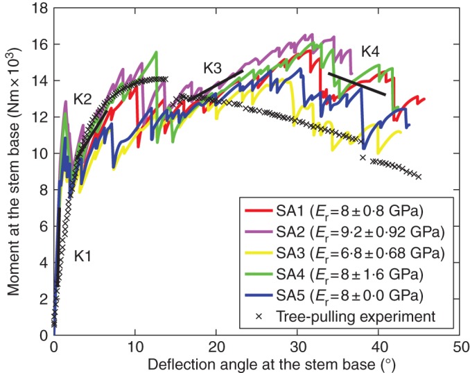
Comparison among five simulations (SA1–SA5) with different data sets of root mechanical parameters and the curve measured from the tree-pulling experiment: turning moment of pulling force against deflection angle at the stem base. K1, K2, K3 and K4 are averaged system stiffnesses (slopes) at four intervals of deflection angle.
Root breakage in comparison with no root breakage
The response curves, i.e. the turning moment of the pulling force against the deflection angle at the stem base, obtained from two simulations (SA6 and SA7) without root breakage were compared with a representative simulation, SA1, defining root breakage and the experiment (Fig. 6). SA6 predicted a continuously increasing turning moment within the considered interval of deflection angle. Therefore, defining the critical turning moment for root anchorage strength would be inappropriate. The turning moment predicted by SA7 reached the global maximum deflection angle at 27·5°, after which it decreased slightly and gradually. The slight decrease in turning moment is probably due to both the negative contribution of soil softening behaviour after plastic yielding and the zero contribution of the root after plastic yielding. Within the considered interval, SA1 predicted a response curve similar to that of the experiment in terms of magnitude of turning moment. SA6 and SA7 predicted clearly much higher values in turning moment with respect to SA1 and the experiment.
Fig. 6.
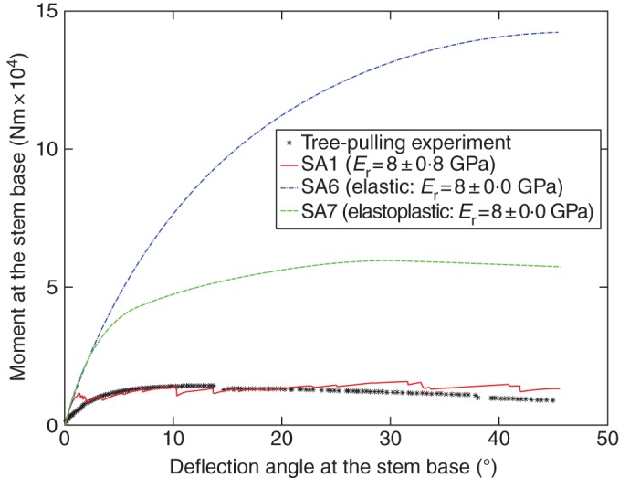
Comparison among the two simulations without root breakage (SA6 and SA7), simulation SA1, including root breakage, and the experiment: turning moment of pulling force against deflection angle at the stem base.
Evolution of apparent stiffness of the root–soil system during the tree-pulling process
Simulations including root breakages exhibited abrupt decreases in the moment–rotation response curves, followed by increases. These local increases characterize the root–soil system strength, which changes during the uprooting process. It can be quantified in terms of apparent stiffness of the root–soil system due to successive breakages and successive activation of new roots to sustain the loading. The trend of system stiffness degradation as a function of deflection angle is thus represented by progressively decreased apparent slopes (i.e. K1, K2, K3 and K4) within four intervals of deflection angle. To determine K1, K2, K3 and K4, we proceeded as follows: (1) for each of the five simulation curves, we first identified four successive intervals with an apparent slope to be determined for each of them; (2) the apparent slope within each interval of the simulation was determined by linear regression; (3) then, each Ki was calculated for interval i as the mean value of apparent slopes from five simulation cases. For all simulations, the first recovery of the turning moment characterized by K2 gave rise to a local maximum turning moment at ≃10°. This interval matched the deflection angle at which the critical turning moment occurred in the experiment (14°). However, the second recovery of turning moment characterized by K3 gave rise to the global maximum at ≃30°, slightly higher than the previous one. Compared with the simulation curves, the curve from the experiment was much smoother, being divisible into three parts marked by two abrupt decreases in turning moment, at 14° and 38° respectively. Recovery after the peak value was small enough to be neglected. Taking the global peak as the critical turning moment, simulations SA1–SA5 overestimated anchorage strength by up to 17·8 %. Another main difference between the measured and simulated response curves was the initial stiffness behaviour. Firstly, the initial stiffness estimated by all simulations was higher than the measured value. Secondly, the measured stiffness gradually decreased, as characterized by the smoothness of the curve, whereas in the simulations the decreases in initial stiffness due to root breakages were abrupt and without transition.
Energy induced by the pulling force: simulations in comparison with the experiment
The fundamentals of continuum damage mechanics have related numerous energy-based concepts and approaches to the damage behaviour of materials (Krajcinovic, 1996; Murakami, 2012). Simulations were analysed using the stored energy of the root–soil system induced by the pulling force. Figure 7 shows the evolution of energy induced by the pulling force as a function of the horizontal displacement at the pulling point during the tree-pulling process, for simulations SA1–SA5 and the experiment. For all the simulations, the energy was in good agreement with that of the experiment. At the initial loading stage (horizontal displacement of pulling point ranging from 0 to 0·2 m) the root–soil system in all the simulations was stiffer than that in the experiment. Therefore, the predicted energy was initially higher in all the simulations.
Fig. 7.
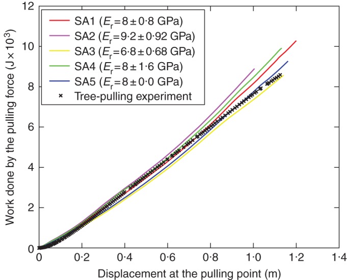
Evolution of the work done by the pulling force during the tree-pulling process predicted by simulations (SA1–SA5) compared with that measured in the tree-pulling experiment.
Linking successive root breakage to tree mechanical response to overturning
Our model can now be used to examine successive root breakage during the uprooting process. Figure 8 illustrates how broken roots can be detected and the connection between successive root breakage and the mechanical effect on root anchorage strength. The response curve shows the turning moment calculated at the stem base versus the deflection angle at the stem base (Fig. 8A). The first square mark on the curve is linked to Fig. 8B1, which shows the state of the intact root system just before the first root breakage. The uniform greenish blue colour in the root system indicates the zero value of the damage variable d (SDV1 in the legend), meaning no damage has occurred. The second square mark on the curve is linked to the state of the root system shown in Fig. 8B2. Figure 8B2 shows the moment after the successive breakage of three finer intermediate roots <2·5 cm in basal diameter, a lateral root 5·5 cm in basal diameter and a thick chuck-like oblique root 8·7 cm in basal diameter. Broken root segments are represented in red in Fig. 8B2. These broken roots reduce the turning moment by 1905 N m. The third square mark corresponds to the moment just before the breakage of a thick lateral root in the counter-winchward direction (the root marked by a circle in Fig. 8B3), and the fourth square mark to the moment immediately after root breakage (the damaged root zone circled in Fig. 8B4). Breakage of this thick lateral root alone leads to a sudden drop of 2130 N m in turning moment. After each drop in turning moment caused by root breakage, the redistribution of stresses released by the broken root(s) to the other roots leads to another recovery of the turning moment. The root breakage tendency (i.e. root types and locations) predicted by our model was compared with field observations during root system excavation. Field observations showed breakage of a large number of relatively finer roots, a large shallow root in the counter-winchward direction and a shallow root in the sector perpendicular to the winchward direction. In particular, the damage in the thick shallow root in the counter-winchward direction was initiated very close to the stump, cracking along a large segment. The detailed root damage state in Figure 8B4 shows that our model predicts qualitatively fairly well the observed root breakage tendency; the same shallow root in the counter-winchward direction was also broken close to the stump, and many small roots were broken.
Fig. 8.
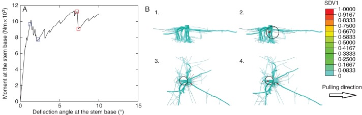
Linking successive root breakage effects to tree overturn response. (A) Turning moment of pulling force against deflection angle at the stem base (SA3) with four squares marking breakage points. (B) Root damage state (SDV1) in the root system at four moments corresponding to square marks on the curve in (A): (1) intact state of the root system related to the first blue square; (2) after several root breakages, marked by a black circle related to the second blue square; (3) state of root damage before breakage of a thick counter-winchward root occurs, marked by a black circle, related to the first red square; (4) state of root after breakage of a thick counter-winchward root occurs, marked by a black circle, related to the second red square.
DISCUSSION
Our strategy for developing the model was to provide a model with the same degree of physical realism for the three main components: (1) root architecture; (2) root mechanical strength; and (3) soil strength. As previous numerical work has focused on root architecture (Dupuy et al., 2005b; Fourcaud et al., 2008), this new model was developed to integrate a more realistic description of individual root behaviour and soil. A constitutive law for root mechanical rupture was developed to describe root failure under tension, bending and compression. Using data from the literature, we established a specific parameterization for root mechanical properties and their variation as a function of root dimensions. This method led to simulation of the successive breakage of roots during uprooting, something that had not been done before. Also, the simulated tree response curve obtained without any calibration was in good agreement with our observations. The following section is devoted to an examination of these results and an assessment of the potential of this new model and its limitations.
Initial root–soil stiffness
The initial stiffness of the root–soil system was not properly estimated by the model. However, it is important to accurately estimate tree inclination in addition to trunk bending under the effect of wind. In particular, to assess the risk of uprooting the initial stiffness is required in order to estimate the moment applied to the crown due to wind and gravity and compare it with the critical turning moment. Moreover, it could be valuable when considering damage resulting from tree inclination after a windstorm without uprooting or breakage, i.e. toppling, usually reported for young trees (Moore et al., 2008), or when considering the wind's interaction with trees for landscape-scale problems (Gardiner et al., 2000). In the latter case, it is common to model the root–soil system without flexibility due to a lack of quantitative information, despite the fact that including flexibility improves prediction (Neild and Wood, 1999; Jonsson et al., 2006). The present model overestimates the initial stiffness of the root–soil system. We performed a sensitivity analysis in order to identify the model parameters responsible for this discrepancy between the simulations and the observations. Four mechanical parameters of roots and soil were selected for this sensitivity analysis. The purpose was to quantify their separate influences on the initial behaviour of the root–soil system characterized by the initial slope of the force–angle response curve. Root tensile strength σt11, compressive strength σc11 and fracture energy Gf were not selected in this analysis, because these parameters are involved in calculations only if root breakage occurs. However, according to the simulation results no root breakage was detected during the early loading stage considered. For all cases the initial stiffness of the root–soil system was calculated as the slope of the response curve for reaction forces ranging from 0 N to 4 kN (Fig. 9). The initial stiffness is supposed to be calculated within the material elastic state of the system. However, in the case of soil cohesion variation of –50 %, the soil zone surrounding the root system was yielding when the reaction force reached 4 kN (blue curve in Fig. 9). The initial stiffness was revaluated just before the first yielding zone appeared in the soil in this case (green curve in Fig. 9). The initial slope of the force–angle response curve is mainly influenced by the modulus of elasticity of the root and soil materials. A variation of ± 50 % in the modulus of elasticity of the roots leads to a variation in the initial slope of –37·5 and +32·1 %, positively related to the input variation. The same variation in the modulus of elasticity of the soil leads to a variation in the initial slope from –19·0 to +8·3 %. Soil cohesion and friction angle are not influential factors as long as the overall soil state remains elastic at the early loading stage considered. For the case of a 50 % decrease in soil cohesion, when the pulling force reached ∼4 kN, the plastic yielding occurred in a zone ∼60 cm in size (including the stump) in the soil domain. The first evaluation of initial stiffness in the force interval [0, 4 kN] gives a decrease of 19·2 % in initial stiffness (blue circles in the third column of Fig. 9). The fact that the yielding area appears on the soil surface at a very early loading stage in this case can be explained by the lower soil shear strength resulting from the reduced soil cohesion, according to the Mohr–Coulomb equation τmax = σn tanϕ + c. Revaluation of initial stiffness was then computed in the interval ranging from the soil initial state to the soil elastic state just before yielding. The result shows that the slight variation of 1·3 % is due to a decrease of 50 % in soil cohesion (green circles in the third column of Fig. 9). Finally, the sensitivity analysis indicates that the overestimate of initial root–soil stiffness is due to the overestimation of input elastic data, namely Er and Es. Thus, the accurate estimation of root–soil stiffness probably requires a good estimate of the elastic modulus for both soil and root. The overestimation is probably due to the lack of data on root mechanical properties. Furthermore, Young's modulus of roots at the early loading stage was found to be lower than average values due to their initial tortuosity, and after stretching roots become stiffer, exhibiting average root material stiffness (Commandeur and Pyles, 1991). In the model, Young's modulus was defined to be constant with respect to root geometry change during the course of tree-pulling, which may potentially lead to overestimation of initial stiffness. This new insight into root–soil stiffness illustrates the potential of the present mechanistic model for further application, such as tree–wind interaction for landscape-scale problems for which root–soil flexibility remains poorly described (Jonsson et al., 2006; Szoradova et al., 2013).
Fig. 9.

Sensitivity analysis of the initial slope of the response curves: initial slope variation versus ±50 % variation in modulus of elasticity of roots (Er), modulus of elasticity of soil (Es), soil cohesion (c) and soil friction angle (ϕ). The initial stiffness of the root–soil system was evaluated twice for the case of a –50 % decrease in soil cohesion (c), with the second evaluation marked by a green circle.
Modelling root failure
The relevance of this new model lies essentially in the improvement obtained in modelling root–soil failure. This gives a more realistic description of every important aspect of the first mechanistic model of root anchorage (Blackwell et al., 1990). For the first time, we have produced a model that simulates root ruptures realistically, by combining a constitutive law for rupture in composite materials and mechanical parameters for wood available in the literature. Our constitutive law accounted for root brittle failure behaviour under tension, compression and bending. We demonstrated through a simulation case that the numerous drops in turning moment were directly linked to successive root breakages. This type of behaviour with successive drops has been reported in previous field investigations on tree-pulling tests (Cucchi, 2004). In addition, the signature of root breakages during uprooting was also reported by Coutts (1983), who measured the sound made by successive root breakages using microphones. This behaviour with successive ruptures was also observed in studies performed to prevent soil erosion by using roots to increase slope stability. This cumulative rupture was reported for numerous field pull-out tests using fine root bundles and this trend could be reproduced in several models adapted from the fibre bundle model (Riestenberg, 1994; Pollen et al., 2004; Schwarz et al., 2012, 2013). In these cases, the problem was to evaluate the contribution of fine roots to soil reinforcement, so only the tensile failure of roots was accounted for, and root diameter was generally <1 cm. In our case, the tree uprooting process involves coarse roots under tension, compression and bending failing progressively, which requires a model dedicated to uprooting.
Compared with previous tree anchorage models, our model is able to provide more realistic response curves with respect to the experiment and predicted a peak value of turning moment that defined properly the critical turning moment (Dupuy et al., 2005b, 2007; Rahardjo et al., 2009). Our results gave fairly accurate descriptions of the behaviour of the root–soil system during tree overturning. Despite the simplifications introduced for root–soil interaction and root material, the estimated critical turning moment was reasonably correct and close to that measured in the experiment. In addition to this first quantitative validation, this new model seems robust in terms of the physics simulated. Our damage model is derived from continuum damage mechanics, for which energy estimation is essential (Murakami, 2012). All the simulations were in good agreement with the experiment in terms of energy induced by the pulling force. A more in-depth analysis of this aspect of the model would require better simulation of the rupture behaviour of individual roots. At this stage, the constitutive law for root rupture is based on the literature and has not been validated by comparison with mechanical tests on individual roots.
Whereas the model appears to estimate the critical turning moment well, it differs from the observations when considering post-rupture behaviour. The simulations exhibited moment–rotation curves that increased after the first stage of the ruptures, contrary to the experimental curve. First from a physics point of view, if larger and stiffer roots take the role of other roots which carried the loads before their breakage, the recovery contributed by these roots may be much more significant than that contributed by roots with lower stiffness (i.e. lower Er or smaller diameter). Our simulations defined higher Er values from the wide range for coarse roots, which could potentially lead to a more significant recovery in turning moment. In addition, this discrepancy could also be partially explained by certain numerical prerequisites. Indeed, the root slippage caused by large deformations of the root–soil system was constrained by the root–soil interaction method used, namely the embedded element method. Thus, potential errors could arise due to the fact that no possible failure occurs at the root–soil interface. Recent developments in understanding soil reinforcement by fine roots permits root–soil interactions to be modelled more accurately by incorporating friction laws for root–soil interaction (Pollen, 2007; Schwarz et al., 2012, 2013). However, friction laws prove to be expensive in terms of computational cost due to complex geometries and interactions in our model. Such a high level of complexity will probably not be required in the near future because the embedded element method turned out to be a good compromise between accuracy and computational cost (see results in Appendix).
Root mechanical properties
One significant result of this study concerns the role of the mechanical strength of roots. By linking the global root–soil system response characterized by the response curve to local root breakages detected by visualization, we are able to detect broken roots at a given moment. The root breakage pattern due to tree-pulling was fairly well imitated, which allowed us to use the model as a diagnostic tool to explain the mechanical role played by the main root components. The results show that root thickness and root location may strongly influence the contribution of the tree response to overturning. Thick counter-winchward lateral roots contribute more significantly to anchorage strength in comparison with relatively fine lateral and intermediate roots. Furthermore, thick counter-winchward lateral roots contribute more than thick oblique roots. For the first time, we highlight the role played by mechanical properties of roots in the tree's response to overturning, as previously suggested by Coutts (1983). In our study, we found that both higher root mechanical strength with higher Er in all roots and higher strength with higher Er only in thicker roots provided better root anchorage, which is reasonably correct. But we had to simplify certain root mechanical properties due to the lack of data on root material. Firstly, relationships among the material properties of coarse roots were assumed to be similar to those in stem wood. Thus, the correlations established between Er and the other three parameters, ρr, σt11 and σc11, for stem wood also applied to roots. However, it is generally believed that the mechanical properties of roots differ from those of stem wood and vary enormously depending on root age, tree species and root physical properties such as cellulose and water contents (Genet et al., 2005). For example, the tensile strength measured for coarse roots may range from 9 to 63 MPa (Coutts, 1983). For the same species (P. pinaster), the longitudinal modulus of elasticity measured may vary from 0·8 to 11 GPa (Stokes et al., 1997; Khuder et al., 2007). The data sets built into all our simulations always took higher values of Er in the range of 0·8–11 GPa, which may lead to estimation errors for all the other parameters related to Er. Furthermore, our sensitivity analysis showed that overestimation of Er potentially led to overestimation of the initial stiffness of the root–soil system. Secondly, relationships between root mechanical properties and root diameter were assumed to be positive linear, based on similar descriptive findings for coarse roots (Stokes and Mattheck, 1996; Khuder et al., 2007). This may have caused estimation errors for root anchorage strength. Moreover, another mechanical parameter, Gf, remained constant for all the simulation cases. This may have led to errors in characterizing root failure behaviour. Finally, we formulated a damage model with an assumption of brittle material for roots. However, load displacement curves from fracture tests on single-edge-notched beams showed that wood in bending exhibited less abrupt post-rupture behaviour than that predicted by our model (Dourado et al., 2008). In conclusion, more experiment results will be needed to improve and validate the damage model for roots.
Soil mechanical properties
This new model was tested using a set of measured soil properties corresponding to the soil conditions of the tree-pulling tests. This represents a significant improvement because previous modelling approaches either did not consider soil material properties or used only literature findings to model general soil mechanical behaviour (Blackwell et al., 1990; Dupuy et al., 2005b; Rahardjo et al., 2009). However, the role of the soil compartment remains poorly described and is treated as a homogeneous medium, so that improvements are required in the future to evaluate its impact on tree anchorage. The presence of a water table, rocks, hardpan and organic matter (dead leaves and stumps, roots, soil surface vegetation etc.) modifies the soil, making it much more porous and far from a homogeneous material, as considered here. In particular, numerous studies confirmed that the local presence of fine roots can improve local soil shear strength by providing additional cohesion to the soil (Waldron, 1977; Wu et al., 1979; Waldron and Dakessian, 1981; Pollen and Simon, 2005; Schwarz et al., 2010; Mao et al., 2012). The present model could be used to investigate the influence of forest soil properties and its spatial variation on tree stability.
Conclusions
This paper presents a new model of tree anchorage capable of simulating root breakages for the first time. It also permits the localization of damage within the root system and includes specific parameterization for root and soil properties based on measurements and experimental evidence reported in the literature. These simulations were performed without any calibration and were found to be in good agreement with the observations. The results are promising enough to allow consideration of further applications to adult trees, which are more vulnerable to uprooting than young specimens. However, the architecture of the root system of adult trees is different from that of young trees for P. pinaster. This could increase the degree of complexity of the model. For example, the formation of a rigid ‘cage’ within a root system is common for older P. pinaster (Danjon et al., 2005). Thus, relevant adaptations for more complex root structures should be made in the model in the future. Nevertheless, our model proved useful for examining the role of root mechanical properties and thus it represents a significant step forward in our understanding of the uprooting process as a function of tree characteristics and soil mechanical properties. Mechanical consequences can also be analysed as a function of certain aspects of root system asymmetry (e.g. leeward chuck-like structure) or other specific root features (e.g. sections of large shallow roots formed as an ‘I’ or oval beam type close to the stump). Therefore, the model could help us understand how trees optimize the allocation of root material. This is particularly important for our comprehension of tree anchorage. The model is also expected to provide useful information on the underground response of trees to uprooting during storms for landscape wind risk models in the future. In particular, by studying the influence of variations in soil material properties on tree overturning behaviour, the model is expected to help us understand the impact of soil management on rooting (cultivation, iron pans, high water tables, indurations and soil saturation).
ACKNOWLEDGEMENTS
This work was supported by the project FAST-A of Aquitaine Region, the project TWIST of the JCC Program of the French National Research Agency and the project ForWind (Ref. ANR-12-AGRO-0007) of the French National Research Agency.
We thank Jean-Marc Bonnefond, Didier Garrigou and Pierre Trichet for their help in the tree-pulling experiments and soil property measurements; Antoine Danquechin Dorval and Raphael Segura for the root architecture measurements; Sébastien Griffon and Hervé Rey for their help in using Xplo software; Mark Irvine for his technical support for the ABAQUS computations; and Dr Sylvain Dupont for fruitful discussions on numerical modelling and his critical reading of our manuscript. We are also deeply grateful to two reviewers for their valuable remarks and suggestions, which offered new insights in this work.
AMAP (Botany and Computational Plant Architecture; http://amap.cirad.fr/) is a joint research unit including CIRAD (UMR51), CNRS (UMR5120), INRA (UMR931), IRD (2M123) and Montpellier 2 University (UM27).
APPENDIX
Preliminary study: comparison of two methods of root–soil interaction modelling
Materials and methods
This work was carried out in the ABAQUS environment, version 6.13 (http://www.3ds.com/products-services/simulia/portfolio/Abaqus/). The preliminary study was conducted with a 3-D model of a direct shear test on root-reinforced sandy soil. We evaluated the results given by two root–soil interaction modelling approaches, namely the embedded element approach and the frictional behaviour approach, to justify (1) the choice of beam elements to discretize the root system, and (2) the choice of the embedded element method to model root–soil interaction. The frictional behaviour method consists of applying a realistic physical law to surfaces in contact so that shear and normal stresses can be transmitted across the interface. However, this method proved unable to cope with multiple complex structures, in our case, for example, a real root system with a high branching order. The embedded element method does not take into account stress transmission across the interface and makes assumptions on translational motions of embedded root elements. Its simplified considerations make this method capable of tackling certain problems with complex geometries.
Fig. A1.
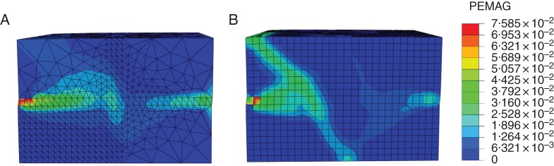
Comparison of two methods of root-soil interaction modelling: frictional behaviour and embedded element. Distribution of plastic deformation magnitude in the soil medium (A) predicted by the frictional behaviour method and (B) predicted by the embedded element method.
Fig. A2.
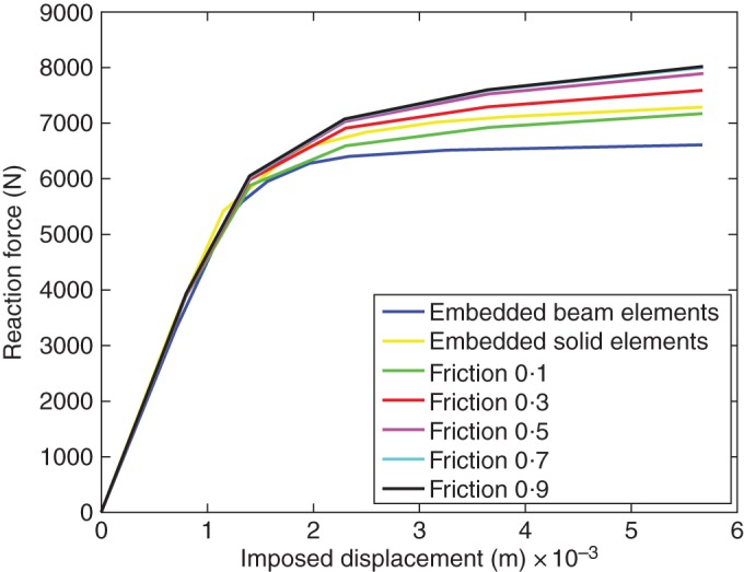
Comparison of two mesh methods and two root-soil interaction models: force-displacement response curves calculated at the centre of the rigid plate predicted by the embedded beam element method, the embedded solid element method and frictional behaviour method with five friction coefficient values: 0·1, 0·3, 0·5, 0·7 and 0·9.
Modelling root–soil mechanical interaction
The embedded element method assumes that all the nodes of root elements are embedded in the host soil region. Each translational kinematic degree of freedom (d.o.f.) of embedded root nodes is calculated using the interpolation values of the corresponding d.o.f. of the soil nodes in the vicinity of the root node automatically searched by a specific algorithm. The region where the root system is located contains two materials, namely roots and soil. The mass and stiffness of embedded roots are added to the model during analysis runs. The method of frictional behaviour applies the Coulomb friction model to the root–soil interface to model possible root slippage in the soil medium:
where τ1 and τ2 are two stress components in two perpendicular tangential directions of the friction surface, μ is the friction coefficient and p is normal pressure on the friction surface. The Coulomb friction model states that no relative motion occurs if the equivalent frictional stress τeq is less than the critical frictional stress τcrit (ABAQUS Theory Guide). In addition, the root and soil surfaces in contact are allowed to separate from each other, but applications to the 3-D anchorage model can lead to either mesh difficulties or convergence problems. In this study, the friction coefficient μ is defined to range from 0·1 to 0·9 for five simulation cases (with different values from the literature ranging from 0·1 to 0·9; data source, Gray and Barker, 2004; Dupuy et al., 2005a).
Model of the direct shear test
The geometry of the soil domain is modelled by a rectangular box 0·5 m in length (x) and width (z) and 0·32 m in height (y). For the case of the embedded element, the root segments are embedded in the soil block. The soil area occupied by root segments actually contains both root and soil materials. The entire soil block is meshed into eight-node linear brick elements (C3D8R in the ABAQUS element library) to avoid convergence difficulties. For the case of frictional behaviour, room for roots was provided in the soil. Four-node linear tetrahedron elements (C3D4 in the ABAQUS element library) are chosen to make the soil zone meshable in the vicinity of the root segments. A refined mesh with an average element size of 1·5 cm is defined within the zone surrounding the location of the roots and the soil shear zone. For both cases, the soil material is assumed to be homogeneous and initially linear elastic combined with plastic behaviour defined by the Mohr–Coulomb criterion (the same definition as that from the anchorage model). The soil data set in Table 1 is used in all the simulations.
The soil is reinforced by 12 identical parallel root segments. They are equidistant (4 cm apart) and vertically placed in the plane in the middle of the soil block perpendicular to the direction of the imposed horizontal displacement. The geometry of the root segments is assumed to be a thin cylinder 2 cm in diameter and 28 cm in length. For the case of the embedded element, the root segments are meshed into two-node linear Timoshenko beam elements. For the case of frictional behaviour, the root segments are meshed into C3D8R elements. The root material is assumed to be homogeneous and linear elastic with the same density and modulus of elasticity as that from SA5, namely a density of 421·4 kg m−3 and a modulus of elasticity of 8 GPa, as well as a Poisson ratio of 0·3.
A thin plate is defined about half the size of the lateral face (14 × 50 cm2) of the soil rectangular box to cover the upper half of the lateral face. The plate is meshed into four-node bilinear rigid elements (R3D4 in the ABAQUS element library) and placed against the upper lateral half-face so it is pushed during the shear process. A reference point is defined at the centre of the plate to prescribe its motions (d.o.f.) and record the imposed displacement and pushing force.
Loadings are defined in two analysis steps: the gravity body force is defined in the first step with gravity acceleration g = 9·81 m s−2 in the downward direction, –y. A normal pressure of 1 kPa is applied on the top face of the soil block. The effect of both loadings is propagated through the second analysis step. The bottom of the soil box is fixed with all d.o.f. constrained to 0 through a two-step analysis (ENCASTRE in the ABAQUS Analysis User's Guide). Soil motions with respect to four laterals are constrained to 0 in the first step (XSYMM and YSYMM in the ABAQUS Analysis User's Guide). During the second step, which is the shear process, the same symmetry constraint is defined for the lower half of the lateral face on the opposite side of the pushed lateral face. The constraints on the other lateral planes are removed and a displacement of 2 cm is imposed at the reference point of the rigid plate so that the upper half of the soil block is driven to move horizontally in direction x.
Three root–soil configurations were used in order to make separate comparisons of the geometry effect of using the beam element and the interaction effect of the embedded element: (1) roots meshed into solid elements in frictional contact with the soil medium; (2) roots meshed into solid elements embedded in the soil medium; and (3) roots meshed into beam elements embedded in the soil medium.
Results
The two methods predict similar results in terms of the distribution of plastic strain magnitude in the soil block at the end of the shear process (Fig. 9): two narrow horizontal soil zones with elevated plastic strain magnitude (PEMAG) start at the mid-height of the soil block from both lateral sides (y, z plane) perpendicular to the direction of the imposed displacement. The plastic zone on the side against the plate stops expanding before arriving at the plane of the 12 root segments and turns obliquely to one side towards the bottom in the middle of the block, and on the other side it turns backwards to the top of the pushing plate. For the case of frictional behaviour, another small soil zone with an elevated plastic strain magnitude can be identified at mid-height in the location of the roots. Since frictional behaviour allows the transmission of normal and shear stresses between the root segments and the soil medium, we can deduce that the root segments make an additional contribution to soil shear, especially in the Mohr–Coulomb failure plane, where they are subjected to larger axial deformations due to soil shearing. The embedded element does not predict such a plastic soil zone at the same location, probably because this interaction approach only consists of the constraint of translational d.o.f. between the root and soil nodes. However, no stress transmission is allowed, which partly limits the additional contribution of the roots to the soil shear process.
Pushing force versus imposed displacement curves are obtained at the reference point on the plate during the analysis runs (Fig. 10). First, we examined the geometry effect of the beam elements by comparing the case of the embedded solid element and the embedded beam element. The curves of the two cases presented good agreement with each other. The initial stiffness of the reinforced soil (the initial slope of the curves) is slightly lower in the case of the beam elements. In addition, the pushing force on the rigid plate after soil yielding predicted by beam elements is smaller by up to 10·2 % at the end of the shear process. Secondly, we examined the effect of the root–soil interaction by comparing the curve of the embedded solid elements to five curves obtained for the frictional behaviour of five friction coefficients, i.e. 0·1, 0·3, 0·5, 0·7 and 0·9. The curve of the embedded solid element is placed exactly between the frictional behaviour curves with friction coefficients of 0·1 and 0·3. Qualitatively, the embedded beam element predicts a curve in good agreement with the curves of frictional behaviour: the initial linear elastic part of the curves has broadly the same slope. Beyond the elastic part the slope decreases gradually, which suggests soil yielding. The largest relative difference in required pushing force between the two interaction methods estimated at the end of shear test is from –1·7 to 9·1 % for all cases of frictional behaviour. For the five cases of frictional behaviour, the global level of reaction force is positively correlated to the friction coefficient. It is reasonable to see that the required pushing force increases with a rougher root–soil interface, which suggests possible stronger stresses transmitted at the interface, making root slippage more difficult. For a friction coefficient >0·5, the force–displacement curves remain almost the same, which suggests that the root–soil interface is rough enough to be insensitive. Despite the difference between the mechanisms defined by the two approaches, the results predicted by the embedded element method are fairly reasonable and probably equivalent to that of the frictional behaviour of a friction coefficient of 0·2.
LITERATURE CITED
- Abernethy B, Rutherford ID. The distribution and strength of riparian tree roots in relation to riverbank reinforcement. Hydrological Processes. 2001;15:63–79. [Google Scholar]
- Ancelin P, Courbaud B, Fourcaud T. Development of an individual tree-based mechanical model to predict wind damage within forest stands. Forest Ecology and Management. 2004;203:101–121. [Google Scholar]
- Bardet JP. Experimental soil mechanics. Upper Saddle River, NJ: Prentice-Hall; 1997. [Google Scholar]
- Blackwell PG, Rennolls K, Coutts MP. A root anchorage model for shallowly rooted Sitka spruce. Forestry. 1990;63:73–91. [Google Scholar]
- Commandeur PR, Pyles MR. Modulus of elasticity and tensile strength of Douglas-fir roots. Canadian Journal of Forest Research. 1991;21:48–52. [Google Scholar]
- Coutts MP. Root architecture and tree stability. Plant and Soil. 1983;71:171–188. [Google Scholar]
- Coutts MP. Components of tree stability in sitka spruce on peaty gley soil. Forestry. 1986;59:173–197. [Google Scholar]
- Coutts MP, Nielsen CCN, Nicoll BC. The development of symmetry, rigidity and anchorage in the structural root system of conifers. Plant and Soil. 1999;217:1–15. [Google Scholar]
- Cucchi V. Sensibilité au vent des peuplements de pin maritime (Pinus pinaster Ait.). Analyse comparative de dégâts de tempête, étude expérimentale et modélisation de la résistance au déracinement. 2004. PhD Thesis, University of Bordeaux 1, France.
- Cucchi V, Meredieu C, Stokes A, et al. Root anchorage of inner and edge trees in stands of maritime pine (Pinus pinaster Ait.) growing in different podzolic soil conditions. Trees—Structure and Function. 2004;18:460–466. [Google Scholar]
- Danjon F, Bert D, Godin C, Trichet P. Structural root architecture of 5-year-old Pinus pinaster measured by 3D digitising and analysed with AMAPmod. Plant and Soil. 1999;217:49–63. [Google Scholar]
- Danjon F, Fourcaud T, Bert D. Root architecture and wind-firmness of mature Pinus pinaster. New Phytologist. 2005;168:387–400. doi: 10.1111/j.1469-8137.2005.01497.x. [DOI] [PubMed] [Google Scholar]
- Danjon F, Khuder H, Stokes A. Deep phenotyping of coarse root architecture in R. pseudoacacia reveals that tree root system plasticity is confined within its architectural model. Plos One. 2013;8(12):e83548. doi: 10.1371/journal.pone.0083548. doi:10.1371/journal.pone.0083548. [DOI] [PMC free article] [PubMed] [Google Scholar]
- Della-Marta PM, Pinto JG. Statistical uncertainty of changes in winter storms over the North Atlantic and Europe in an ensemble of transient climate simulations. 2009. Geophysical Research Letters 36.
- Dourado N, Morel S, de Moura MFSF, Valentin G, Morais J. Comparison of fracture properties of two wood species through cohesive crack simulations. Composites Part A. 2008;39:415–427. [Google Scholar]
- Dupuy LX, Fourcaud T, Stokes A. A numerical investigation into factors affecting the anchorage of roots in tension. European Journal of Soil Science. 2005a;56:319–327. [Google Scholar]
- Dupuy LX, Fourcaud T, Stokes A. A numerical investigation into the influence of soil type and root architecture on tree anchorage. Plant and Soil. 2005b;278:119–134. [Google Scholar]
- Dupuy LX, Fourcaud T, Lac P, Stokes A. A generic 3D finite element model of tree anchorage integrating soil mechanics and real root system architecture. American Journal of Botany. 2007;94:1506–1514. doi: 10.3732/ajb.94.9.1506. [DOI] [PubMed] [Google Scholar]
- Fourcaud T, Ji J-N, Zhang Z-Q, Stokes A. Understanding the impact of root morphology on overturning mechanisms: a modelling approach. Annals of Botany. 2008;101:1267–1280. doi: 10.1093/aob/mcm245. [DOI] [PMC free article] [PubMed] [Google Scholar]
- Gardiner B, Blennow K, Carnus J-M, et al. Destructive storms in european forests: past and forthcoming impacts. Brussels: EFIAtlantic; 2010. [Google Scholar]
- Gandhi K, Gilmore DW, Katovich SA, Mattson WJ, Zasada JC, Seybold SJ. Catastrophic windstorm and fuel-reduction treatments alter ground beetle (Coleoptera: Carabidae) assemblages in a North American sub-boreal forest. Forest Ecology and Management. 2008;256:1104–1123. [Google Scholar]
- Gardiner B, Peltola H, Kellomaki S. Comparison of two models for predicting the critical wind speeds required to damage coniferous trees. Ecological Modelling. 2000;129:1–23. [Google Scholar]
- Gardiner B, Byrne K, Hale S, et al. A review of mechanistic modelling of wind damage risk to forests. Forestry. 2008;81:447–463. [Google Scholar]
- Genet M, Stokes A, Salin F, et al. The influence of cellulose content on tensile strength in tree roots. Plant and Soil. 2005;278:1–9. [Google Scholar]
- Godin C, Caraglio Y. A multiscale model of plant topological structures. Journal of Theoretical Biology. 1998;191:1–46. doi: 10.1006/jtbi.1997.0561. [DOI] [PubMed] [Google Scholar]
- GPMF . Sylviculture et stabilité. France: GIS Groupe Pin Maritime du Futur; 2011. Les Cahiers de la Reconstitution, No. 1. Cestas. [Google Scholar]
- Gray DH, Barker D. Root-soil mechanics and interactions. In: Bennett SJ, Simon A, editors. Riparian vegetation and fluvial geomorphology. Washington, DC: American Geophysical Union; 2004. pp. 113–123. [Google Scholar]
- Griffon S, de Coligny F. AMAPstudio: an editing and simulation software suite for plants architecture modelling. 2013. Ecological Modelling, in press.
- Jonsson MJ, Foetzki A, Kalberer M, Lundström T, Ammann W, Stoeckli V. Root-soil rotation stiffness of Norway spruce (Picea abies (L.) Karst) growing on subalpine forested slopes. Plant and Soil. 2006;285:267–277. [Google Scholar]
- Kamimura K, Kitagawa K, Saito S, Mizunaga H. Root anchorage of hinoki (Chamaecyparis obtusa (Sieb. Et Zucc.) Endl.) under the combined loading of wind and rapidly supplied water on soil: analyses based on tree-pulling experiments. European Journal of Forest Research. 2012;131:219–227. [Google Scholar]
- Khuder H, Stokes A, Danjon F, Gouskou K, Lagane F. Is it possible to manipulate root anchorage in young trees? Plant and Soil. 2007;294:87–102. [Google Scholar]
- Krajcinovic D. Damage mechanics. Amsterdam: Elsevier Science; 1996. [Google Scholar]
- Kretschmann DE. Wood handbook: wood as an engineering material. Madison, WI: Forest Products Laboratory, US Department of Agriculture; 2010. Mechanical properties of wood. Chapter 5. [Google Scholar]
- Linde P, Pleitner J, de Boer H, Carmone C. Modelling and simulation of fibre metal laminates. 2004. ABAQUS Users' Conference.
- Lundström T, Jonas T, Stoeckli V, Ammann W. Anchorage of mature conifers: resistive turning moment, root–soil plate geometry and root growth orientation. Tree Physiology. 2007;27:1217–1227. doi: 10.1093/treephys/27.9.1217. [DOI] [PubMed] [Google Scholar]
- Mao Z, Saint-André L, Genet M, et al. Engineering ecological protection against landslides in diverse mountain forests: choosing cohesion models. Ecological Engineering. 2012;45:55–69. [Google Scholar]
- McCarthy JK, Hood IA, Brockerhoff EG, et al. Predicting sapstain and degrade in fallen trees following storm damage in a Pinus radiata forest. Forest Ecology and Management. 2010;260:1456–1466. [Google Scholar]
- Moore JR. Differences in maximum resistive bending moments of Pinus radiata trees grown on a range of soil types. Forest Ecology and Management. 2000;135:63–71. [Google Scholar]
- Moore JR, Tombleson JD, Turner JA, der Colff M. Wind effects on juvenile trees: a review with special reference to toppling of radiata pine growing in New Zealand. Forestry. 2008;81:377–387. [Google Scholar]
- Murakami S. Continuum damage mechanics: a continuum mechanics approach to the analysis of damage and fracture. Dordrecht: Springer; 2012. [Google Scholar]
- Neild SA, Wood CJ. Estimating stem and root-anchorage flexibility in trees. Tree Physiology. 1999;19:141–151. doi: 10.1093/treephys/19.3.141. [DOI] [PubMed] [Google Scholar]
- Nicoll BC, Ray D. Adaptive growth of tree root systems in response to wind action and site conditions. Tree Physiology. 1996;16:891–898. doi: 10.1093/treephys/16.11-12.891. [DOI] [PubMed] [Google Scholar]
- Nicoll BC, Bardiner BA, Rayner B, Peace AJ. Anchorage of coniferous trees in relation to species, soil type, and rooting depth. Revue Canadienne de Recherche Forestière. 2006;36:1871–1883. [Google Scholar]
- Nicoll BC, Gardiner BA, Peace AJ. Improvements in anchorage provided by the acclimation of forest trees to wind stress. Forestry. 2008;81:389–398. [Google Scholar]
- Niklas KJ, Spatz H-C. Worldwide correlations of mechanical properties and green wood density. American Journal of Botany. 2010;97:1587–1594. doi: 10.3732/ajb.1000150. [DOI] [PubMed] [Google Scholar]
- Peltola H, Kellomaki S, Vaisanen H, Ikonen V-P. A mechanistic model for assessing the risk of wind and snow damage to single trees and stands of Scots pine, Norway spruce, and birch. Revue Canadienne de Recherche Forestière. 1999;29:647–661. [Google Scholar]
- Pollen N. Temporal and spatial variability in root reinforcement of streambanks: accounting for soil shear strength and moisture. Catena. 2007;69:197–205. [Google Scholar]
- Pollen N, Simon A. Estimating the mechanical effects of riparian vegetation on stream bank stability using a fiber bundle model. Water Resources Research. 2005;41:W07025. doi:10.1029/2004WR003801. [Google Scholar]
- Pollen N, Simon A, Collison A. Advances in assessing the mechanical and hydrologic effects of riparian vegetation on streambank stability. In: Bennett SJ, Simon A, editors. Riparian vegetation and fluvial geomorphology. Washington, DC: American Geophysical Union; 2004. pp. 125–139. [Google Scholar]
- Rahardjo H, Harnas FR, Leong EC, Tan PY, Fong YK, Sim EK. Tree stability in an improved soil to withstand wind loading. Urban Forestry & Urban Greening. 2009;8:237–247. [Google Scholar]
- Riestenberg MM. Anchoring of thin colluvium by roots of sugar maple and white ash on hillslopes in Cincinnati. US Geological Survey Bulletin 2059-E. Washington, DC: United States Government Printing Office; 1994. [Google Scholar]
- Schwarz M, Lehmann P, Or D. Root-soil mechanical interactions during pullout and failure of root bundles. Journal of Geophysical Research. 2010;115:F04035. doi:10.1029/2009JF001603. [Google Scholar]
- Schwarz M, Cohen D, Or D. Spatial characterization of root reinforcement at stand scale: theory and case study. Geomorphology. 2012;171:190–200. [Google Scholar]
- Schwarz M, Giadrossich F, Cohen D. Modeling root reinforcement using root-failure Weibull survival function. Hydrology and Earth System Sciences. 2013;10:3843–3868. [Google Scholar]
- Stokes A, Mattheck C. Variation of wood strength in tree roots. Journal of Experimental Botany. 1996;47:693–699. [Google Scholar]
- Stokes A, Fitter AH, Coutts MP. Responses of young trees to wind and shading – effects on root architecture. Journal of Experimental Botany. 1995;46:1139–1146. [Google Scholar]
- Stokes A, Martin F, Sacriste S, Fourcaud T. Adaptation of tree roots to wind loading: the relationship between mechanical behaviour and wood formation. 1997. Plant Biomechanics 339–346.
- Szoradova A, Praus L, Kolarik J. Evaluation of the root system resistance against failure of urban trees using principal component analysis. Biosystems Engineering. 2013;115:244–249. [Google Scholar]
- Tamasi E, Stokes A, Lasserre B, et al. Influence of wind loading on root system development and architecture in oak (Quercus robur L.) seedlings. Trees—Structure and Function. 2005;19:374–384. [Google Scholar]
- Waldron LJ. Shear resistance of root-permeated homogeneous and stratified soil. Soil Science Society of America Journal. 1977;41:843–849. [Google Scholar]
- Waldron LJ, Dakessian S. Soil reinforcement by roots – calculation of increased soil shear resistance from root properties. Soil Science. 1981;132:427–435. [Google Scholar]
- Wu TH, Mckinnell WP, Swanston DN. Strength of tree roots and landslides on Prince of Wales Island, Alaska. Canadian Geotechnical Journal. 1979;16:19–33. [Google Scholar]