Abstract
This paper reports the development of an MRI-Safe robot for direct (interventional) MRI-guided endorectal prostate biopsy. The robot is constructed of nonmagnetic and electrically nonconductive materials, and is electricity free, using pneumatic actuation and optical sensors. Targeting biopsy lesions of MRI abnormality presents substantial clinical potential for the management of prostate cancer.
The paper describes MRI-Safe requirements, presents the kinematic architecture, design and construction of the robot, and a comprehensive set of preclinical tests for MRI compatibility and needle targeting accuracy. The robot has a compact and simple 3 degree-of-freedom (DoF) structure, two for orienting a needle-guide and one to preset the depth of needle insertion. The actual insertion is performed manually through the guide and up to the preset depth. To reduce the complexity and size of the robot next to the patient, the depth setting DoF is remote.
Experimental results show that the robot is safe to use in any MRI environment (MRI-Safe). Comprehensive MRI tests show that the presence and motion of the robot in the MRI scanner cause virtually no image deterioration or signal to noise ratio (SNR) change. Robot’s accuracy in bench test, CT-guided in-vitro, MRI-guided in-vitro and animal tests are 0.37mm, 1.10mm, 2.09mm, and 2.58mm respectively. These values are acceptable for clinical use.
Index Terms: MRI-Safe, MRI-compatible, pneumatic, motor, robot, prostate biopsy
I. Introduction
In 2013, an estimated 238,590 new prostate cancer (PCa) cases will be diagnosed in the US alone [1]. A large number of these represent indolent tumors unlikely to limit the lifespan of the patient. A study has shown that it is necessary to treat 48 men to prevent one death from PCa, suggesting that significant overtreatment exists [2]. Still, many PCa are aggressive expecting to cause 29,720 mortalities this year [1]. Therefore, a more comprehensive diagnostic approach is needed to differentiate indolent and harmless tumors from aggressive and lethal PCa in individual patients.
The most common way of diagnosing PCa is the transrectal ultrasound (TRUS) guided prostate biopsy. But, standard grayscale ultrasound provides minimal PCa specific information being unreliable in differentiating PCa from normal gland tissues. The biopsy procedures are cancer “blind”, aiming to sample the gland systematically in search of possible tumors. Since PCa is a heterogeneous multifocal disease, untargeted biopsies often lead to the detection of small, clinically insignificant tumors and/or miss significant cancers [3, 4].
A noticeable solution to sample significant cancer with few biopsies is cancer-image-guided targeting. Among other imaging modalities, MRI provides the highest spatial and contrast resolution on prostate anatomy [5]. Functional MRI techniques (MR spectroscopy, diffusion-weighted, and dynamic contrast-enhanced imaging) have shown substantial potential to complement T2-weighted MRI in improving prostate cancer localization [4]. Even though no current imaging method can absolutely differentiate benign from malignant prostate lesions, imaging could point to abnormities that should be biopsied.
One of the simplest methods of biopsy targeting is MRI-TRUS image fusion. In this approach MRI is acquired ahead of time. Then, the biopsy is guided as usual based on the TRUS, but with guidance from the MRI which is fused (registered) to the interventional TRUS. As such, cancer suspicious regions (CSR) of image abnormality depicted in MRI may be targeted under TRUS guidance. However, targeting accuracy relies heavily on challenging cross-modality image-to-image registration [6] and deformable registration methods [7, 8]. MRI-TRUS fusion is most likely superior to traditional systematic methods, but requires further validation and it remains to be tested if it is sufficiently accurate to make a clinical difference [9].
A more involved but highly promising CSR targeting method is to use the MRI directly for guiding the intervention. A few groups investigated the use of manually operated needle-guide devices in the MRI scanner [10, 11]. But these manual devices may be difficult to operate due to the limited access within the scanner and table movements are required to access the patient.
A noticeable solution to guide the needle remotely in the MRI scanner is to employ robotic assistance. However, making a robot that can operate safely and accurately in the MRI without being influenced by and without interfering with the functionality of the imager has been a very challenging engineering task. MRI scanners use magnetic fields of very high density (3 Tesla becoming common), with pulsed magnetic and radio frequency fields. Within the imager, ferromagnetic materials are exposed to very high magnetic interaction forces and heating may occur in conductive materials by electromagnetic induction. The use of electricity may cause interference leading to signal to noise attenuation, signal distortions, and image artifacts. As such, most of the components commonly used in robotics may not be used in close proximity of the MRI. For example, the ubiquitous electromagnetic motor is clearly MRI-unsafe because it functions based on magnetism.
The American Society for Testing and Materials (ASTM) has set a series of standards to test (ASTM F2052, F2213, F2182, F2119) and classify (ASTM F2503) devices for the MRI environment, as shown in Table 1. In the United States, compliance to these standards is required for medical device regulatory clearance by the Food and Drug Administration (FDA).
Table 1.
ASTM F2503 classification for the MRI environment
 |
Is an item that poses no known hazards in all MR environments. |
 |
Is an item that has been demonstrated to pose no known hazards in a specified MR environment with specified conditions of use. Field conditions that define the specified MR environment include field strength, spatial gradient, dB/dt (time rate of change of the magnetic field), radio frequency (RF) fields, and specific absorption rate (SAR). |
 |
Is an item that is known to pose hazards in all MR environments. |
Several non-ferrous metals such as titanium, beryllium copper, and nitinol have been found to be MRI-Conditional for small size parts and are used in commercial MRI passive devices (biopsy needles for example) [12]. However, for noninterference with electro-magnetism the ideal materials should be not only nonmagnetic but also nonconducting, such as plastic, rubber, or glass [13, 14]. Interestingly, carbon fiber is not inherently MRI-Safe because it is a good electrical conductor.
The ASTM standards specifically note that items may classify as MRI-safe on a scientifically based rationale of being nonconducting and nonmagnetic.
From the energetic point of view, electricity will likely exclude the MRI-Safe option, because currents generate electromagnetic waves and require wires. Electric devices could be MRI-Conditional at best. Hydraulic actuation may be MRI-Safe, but leakage may be difficult to control especially when nonmetallic components are used [15]. Pneumatics and light on the other hand are ideal MRI-Safe energy choices, because they are decoupled from electromagnetism.
Most previous attempts to make direct MRI-guided robots used nonmagnetic piezoelectric motors [16–18]. Image interference has traditionally been a problem. Even without power, it was shown that the wiring could debase the signal-to-noise-ratio (SNR) by as much as 50% [19]. Screening and filtering have been employed to cope with these problems and incremental gain was progressively achieved. Innovative recent development of special motor control circuits suggest that acceptable image quality may be achieved [17, 20]. However, the use of piezoelectric motors (including ceramic types) in a MRI device will likely limit its ASTM qualification to MRI-Conditional because the electric actuation will likely disqualify it as MRI-Safe.
Alternatively, pneumatic actuation is a fundamentally flawless MRI-safe option. But, the major limitation of classic pneumatic actuators is their difficult servo control, which in the MRI is even more intricate because the valves must be located distally making the hoses relatively long. Moreover, pneumatic cylinders are direct drive actuators that may be unsafe for medical use [21]. Breaks have been proposed to increase safety, for example to lock the device in place while inserting a needle [22, 23]. But this only works when the robot is at rest. Moreover, due to the additional complexity the robots still included metallic components [22–25], somewhat debasing the SNR [25]. The former Innomotion company (Germany) devised a purpose-built pneumatic cylinder for MRI [26]. Very ingeniously, this increased the sliding friction relative to the stiction (static friction) to unbalance the unfavorable influence of the latter in servo-control. But the cylinder was sensitive to disturbances such as small temperature changes and, unfortunately, the company is no longer active in this field.
A pneumatic turbine-based motor was recently reported from the Nijmegen Medical Centre in the Netherlands and the device is entirely built of nonmetallic components [27]. This represents a very promising MRI-safe engineering solution. The device applies to direct MRI-guided endorectal prostate biopsy and is the first actuated device for the application to be tested clinically [28]. Yet, a technology limitation is that the actuators of the device are not yet encoded, so that this is a remote controlled device rather than a robot. The device is operated by a physician observing the MRI, which may be difficult due to relative long acquisition times of MRI. However, technical advances are reportedly in progress.
We have also developed a motor for the MRI, the Pneumatic Step Motor, PneuStep [29]. With this, we have previously developed an MRI-Safe and MRI-Stealth robot for transperineal needle access [30–32].
Hitherto, very few interventional MRI-guided prostate biopsy devices have been tested clinically [11, 28] in very few patients. Yet, these have shown the feasibility of interventional MRI and CSR biopsy targeting, and that these may selectively improve the detection of significant prostate cancer. Further device developments and clinical validations are needed to evaluate the clinical role of biopsy targeting.
We present the development of a new robot based on updated PneuStep motor technology. The control hardware was also revised for performance and MRI-Safe logistics. The paper presents the kinematic architecture, design, and construction of the robot. We show that only 3 degrees of freedom (DoF) are necessary and sufficient to target the gland transrectally. One of these DoF is implemented remotely and represents a novel way of setting the depth of needle insertion. Previous similar devices use only 2 DoF, leaving the user to choose the depth [18, 33, 34]. Motion bench tests, interference with MRI experiments, and in-vitro image-guided targeting accuracy tests are presented. Image-to-robot registration, image-guided control, and animal experiments are described briefly.
II. MRI-Safe Actuation
As shown above, common motor types are not entirely suitable for the MRI environment, because none can collectively satisfy the reliability, precision, and safety required for a medical robot to function in the MRI without interfering with its functionality. In short available types may either be MRI-unsafe, or imprecise and clinically unsafe, or cause image distortions.
Rather than coping with the incompatibilities of other types and avoid known engineering problems, we have developed a new type of motor built specifically for the MRI, the PneuStep [29], a pneumatic step motor. With a stepper precision is bound within the step resolution, independent of other factors such as the supply pressure. This inherently offers simple, reliable, and precise motion [29] that circumvents the challenging problem of pneumatic servo-control. The PneuStep is entirely constructed of MRI-Safe materials, which are nonmagnetic and nonconductive such as plastics and rubbers. Its sensors are built with fiber optics, so that the motor is electricity free.
The PneuStep motor is MRI-Safe according to ASTM F2503 based on the scientific rational and comprehensive testing [29, 30]. These have shown that the PneuStep operates precisely and without interfering with the MRI, even if located at the image isocenter of virtually any magnetic field imager [30]. The PneuStep satisfies the combined MRI-safe, image non-interference, precision, safety and reliability required for MRI-guided devices.
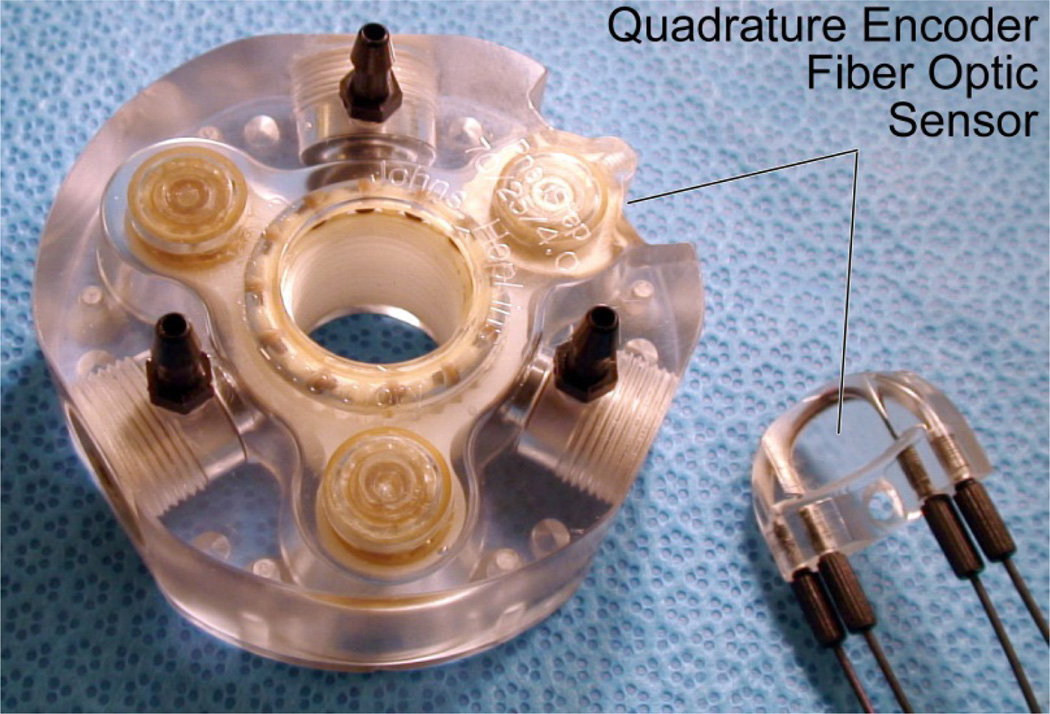
For the biopsy robot the PneuStep has been revised (Figure 1) with a more compact size (from Ø85×45mm to Ø70×25mm), a calipers-shaped detachable optical encoder that makes it easy to service the motor and fibers, a 12 counts/cycle code-wheel to measure the 6 half-steps/cycle of the drive (quadrature encodes multiple of 4, can’t do 6), and a special control using piezoelectric valves which will be detailed in Section VI.
Figure 1.
PneuStep motor used in the robot
III. Robot-Assistant Device and Biopsy Workflow
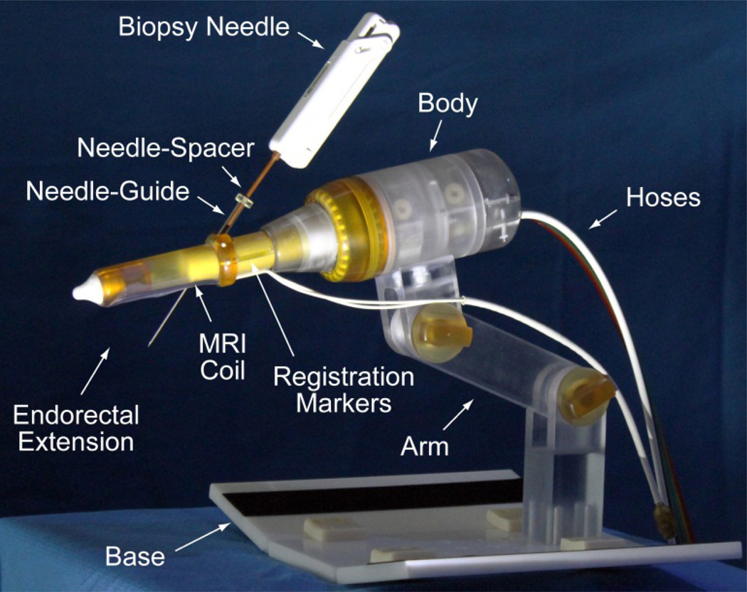
A novel robotic-assistant device for endorectal prostate biopsy was developed. The device assists the physician by automatically orienting a needle-guide on target and setting the depth of needle insertion under MRI guidance. The target is selected by the physician in the MRI. Needle insertion and biopsy are performed manually, as usual, but guided by the device. A photograph of the robot is presented in Figure 2.
Figure 2.
The robotic-assistant device
The robot attaches with a base plate to the MRI couch, after placing the patient in the prone position. The endorectal extension is then placed manually, like a TRUS probe or endorectal MRI coil. The support arm is locked in place to maintain this position throughout the procedure. Robotic motion is generated by the PneuStep motors located within the body of the robot. These are controlled with air and light through a bundle of hoses that connects the robot to an interface and controller (Section VI).
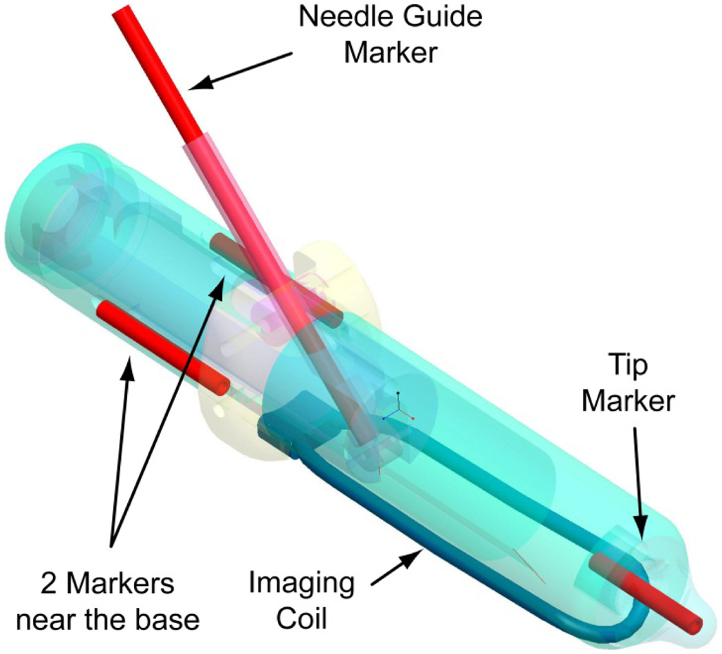
The endorectal extension includes an MRI coil and a set of registration markers for the image-to-robot registration. The needle-guide passes the endorectal extension at an angle that is automatically adjusted by the robot. A needle-spacer is attached to the biopsy needle adjusting its effective length to set the depth of insertion. Its length of the needle-spacer is adjusted automatically by a remote device (Section V).
IV. Kinematic Structure
The architecture and motion of the robot were optimized for the accuracy of prostate biopsy. For accurate image-guided biopsy, it is essential that at the time when the biopsy is targeted the prostate has not geometrically changed from its initially imaged state, based on which the biopsy target was selected. This implies that the motion of the device required to align the needle-guide on target should not move or deform (displace + deform ≡ deflect) the gland. Preventing deflections circumvents the difficult task of compensating for them.
With a TRUS-Robot that we have also built [35, 36] we verified that prostate deflections are unobservable if the TRUS probe is held in place and only rotated about its axis.
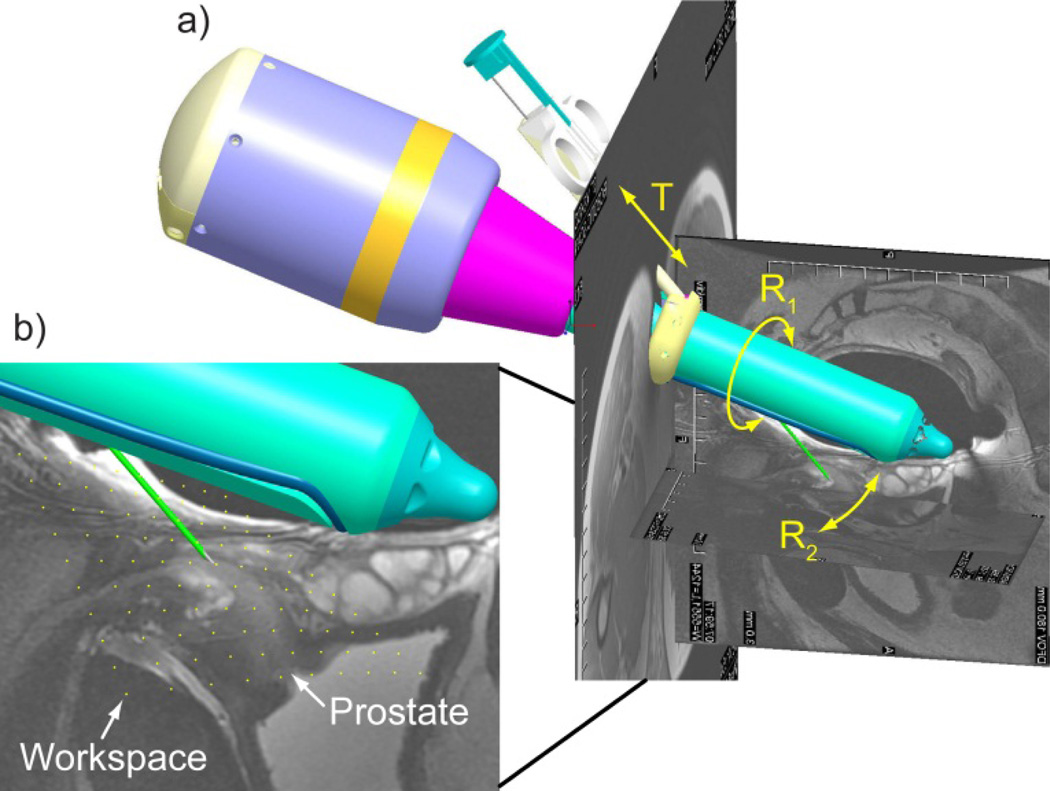
The kinematics of the reported robot was formulated similarly, with low DoF and purely rotary motion of the endorectal extension. Biopsy targeting was simulated in a combined Computer Aided Design (CAD) – MRI environment. For this, MR images were registered to the robot space simulated in Creo (former Pro/Engineer, Parametric Technology Corporation, Needham, MA), as shown in Figure 3a.
Figure 3.
a) Robot CAD with MRI of the prostate and b) needle point workspace density plot in sagittal view.
The robot presents 3DoF: R1 – a rotation of the endorectal extension about its axis relative to the fixed robot body; R2 – a rotation of the needle-guide relative to the endorectal extension; T – a translation for inserting the needle through the needle-guide.
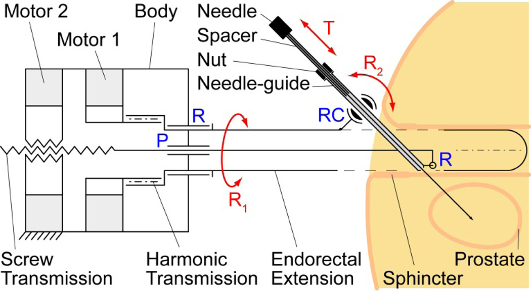
The kinematic diagram of the robot is presented in Figure 4. A first motor adjusts the angle of the endorectal extension (R1) supported by a revolute joint (R) through a harmonic transmission. The second motor engages a screw transmission supported by a prismatic joint (P) and slides the bottom of the needle-guide through a revolute joint (R). The top of the needle-guide slides through a revolute-cylindrical joint (RC, zero link length) that is attached to the endorectal extension. The needle-spacer is mounted on the needle and a nut is threaded to it. The position of the nut over the spacer is adjusted automatically by the remote DoF (Section V). Using a remote DoF reduced the size and complexity of the robot. Manually, the needle is then inserted fully through the needle-guide (T), until the nut stops at the top of the needle-guide.
Figure 4.
Kinematic diagram with pelvic structures
As shown above, this kinematic architecture has been chosen based on several clinical considerations (Figure 4):
Since the needle-guide passes through the endorectal extension and does not protrude at the bottom, rotations of the extension (R1) are unlikely to deflect the gland.
The precision of targeting increases if the exit of the needle-guide is as close as possible to the target (prostate). The revolute joint (R) at the bottom of the needle-guide maintains the guide as close as possible independent of the angulation R2.
Placing the needle-guide angulation pivot (RC) at the top of the extension and as close as possible to the anus reduces the interference of the needle-path with the anal sphincter.
The same clinical application and endorectal constrains have led to the development of another system with similar kinematics [18]. A manually operated version of this device has been used in clinical trials [11, 34]. Manually operated devices [10] have been the first to clinical tests and had major contributions to test the feasibility of interventional MRI.
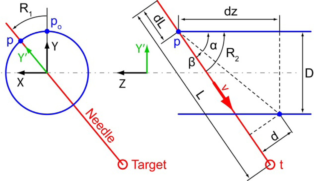
The kinematics of the 3DoF manipulator can be derived as follows. The robot XYZ coordinate system is attached to the endorectal probe as shown in Figure 5. Motor 1 rotates its output shaft with angle θ1 and engages a harmonic transmission (ratio H) that rotates the endorectal extension about the Z axis with angle R1 = H θ1. This rotates the center point p0 of the RC joint and the direction of the Y axis to:
Figure 5.
Diagram for kinematic calculations
The needle-guide angulation mechanism operates in the Y'Z plane adjusting the needle-guide angle R2. Its direction ν is:
with R2 = α + β. Their values can be calculated as tan α = D/dz and sin , where D and d are constant design parameters and dz = dz0 + P(θ2 − R1), where θ2 is the output angle of Motor 2, P is the pitch of the screw transmission and dz0 is a constant design parameter. The direct kinematics position of the needle point in robot coordinates as a function of the motor angles is given by:
where (L − dL) is a length of the needle L, adjusted by needle spacer, and dL = Pd θ3, where Pd is the pitch of the depth adjusting screw θ3 is the output of the 3rd motor (Section V).
The inverse kinematics can also be derived analytically. If t = [tX, tY, tZ]T is a given target point in robot coordinates,
Similarly, the direction of the needle-guide should be aligned with , therefore:
Finally, the needle-depth is adjusted so that:
Within the range of motion the robot presents no singularities. The workspace of the needle point has been calculated based on the direct kinematics presented above and also simulated in CAD. For simplicity, the result is presented in the sagittal plane (Figure 3b, yellow dots). As shown, the density plot spans across the entire prostate confirming that the 3 selected DoF are sufficient to target the gland. Moreover, 3 DoF are also necessary to target in 3D.
V. Robot Design and Prototype
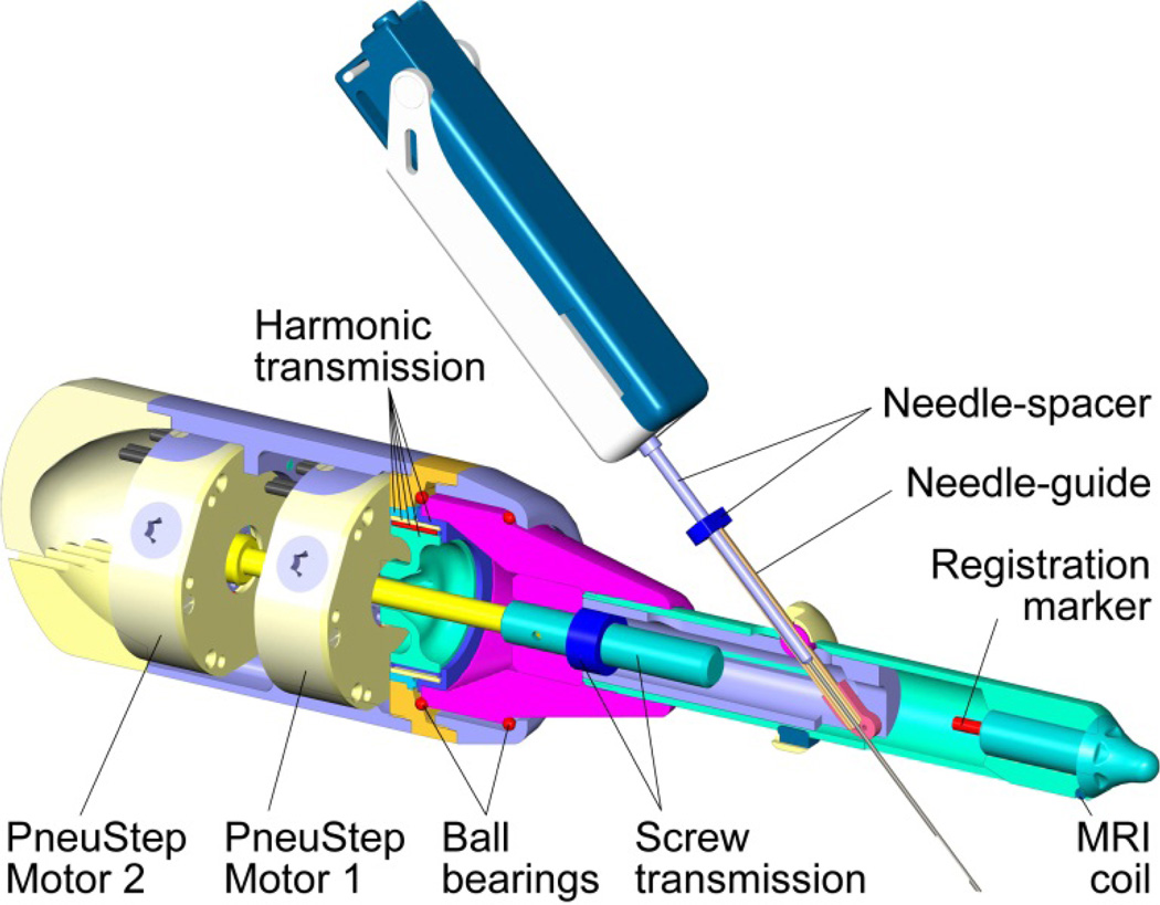
The robot was designed and manufactured in Creo using kinematic simulation and analysis, Geometric Element Methods (GEM) for the structural analysis, and computer aided manufacturing. A central cross-section of the robot design is shown in Figure 7. The robot uses PneuStep motors. These present a hollow output shaft, making it convenient to juxtapose the motors and pass one’s output through the other. The output of Motor 1 engages the wave generator of a harmonic transmission. Its output drives a part at the base of the endorectal extension. This is supported by two custom ball bearings built within the parts. Motor 2 drives a shaft that passes through the bore of Motor 1 and engages the screw of the transmission actuating the angulation of the needle-guide. For simplicity, the kinematic diagram (Figure 4) shows the motor engaging the nut (same kinematics). The endorectal extension may be disassembled by unthreading it from the body. One of the registration markers and a part of the MRI coil are also shown in Figure 7.
Figure 7.
Central cross-section of the robot
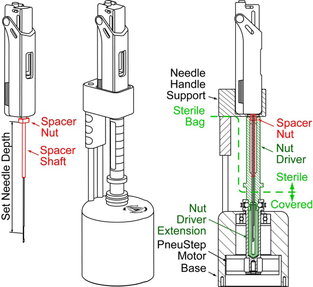
The design of the remote DoF for presetting the depth of needle insertion, the needle-spacer driver, is presented in Figure 6. The spacer assembly comprises a threaded spacer shaft and a nut. The device adjusts the effective length of the needle by spinning the nut on the shaft. For this, the needle-spacer assembly is placed into the device, where the nut is engaged by a (sterile) shaft controlled by a third PneuStep motor. The needle handle support is built for the Invivo Fully Automatic Biopsy Gun, 18G 175mm (Gainesville, FL).
Figure 6.
Needle-depth driver
The robot and needle-spacer driver have been built with three identical PneuStep motors of Ø70 × 25 mm size and 6*15=90 steps/turn (Figure 1). With the screw and harmonic transmissions the step resolutions are 0.082°/step, 28µm/step, and 7µm/step for the R1 axis, the linear drive of the R2, and the needle-depth preset (T), respectively. All parts have been built of plastic, rubber, glass, and ceramic materials. Parts that come in contact with the sterile needle must be sterilized. These include the endorectal extension needle-guide and several parts of the needle-depth driver (Figure 6). The endorectal extension is covered with a condom, as usual, and the robot body and depth driver are covered with sterile bags.
VI. Robot Control
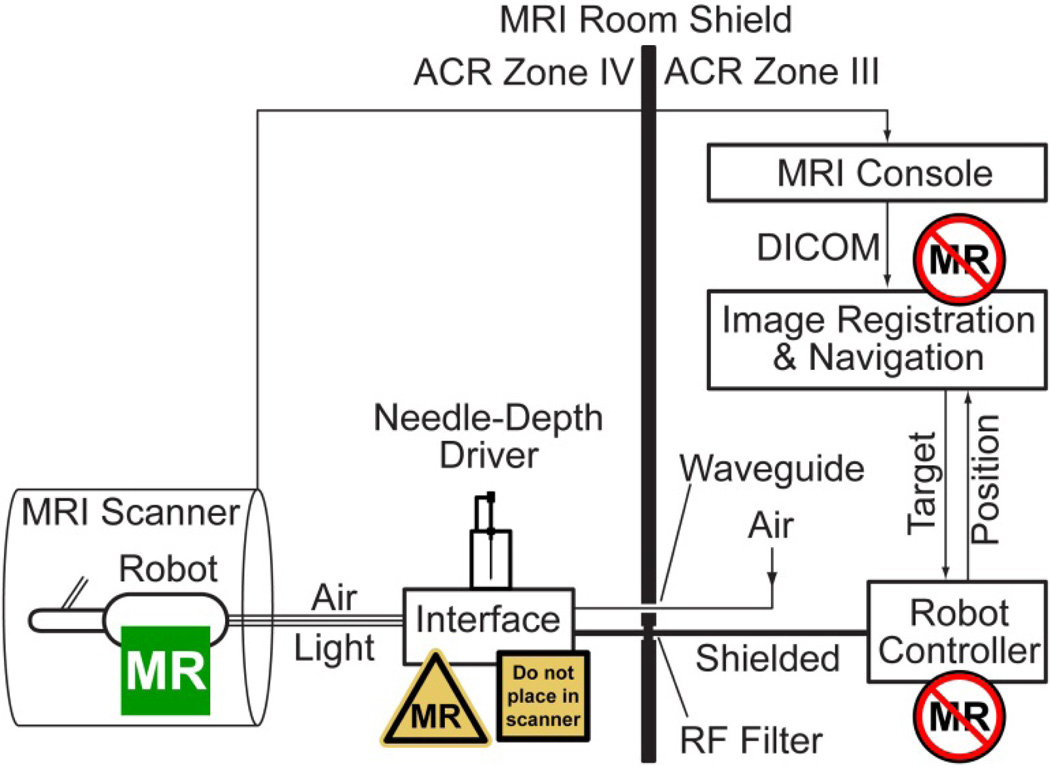
A schematic of the robotic system is presented in Figure 8. The Robot Controller is a PC based computer running Windows XP (Microsoft Corp.) equipped with a motion control card (MCC) (MC4000, PMDI, Victoria, BC, Canada). This is MR-Unsafe and must remain outside the ACR (American College of Radiology) Zone IV (scanner room), in the ACR Zone III (control room or equipment room) [37].
Figure 8.
Control of the MR-Safe robot with an MR-Conditional electro-pneumatic and electro-optical Interface and MR-Unsafe Robot Controller
The PneuStep motors use air pressure for actuation and light for the sensors. Electro-pneumatic and electro-optical interfaces are used to control the robot. The electro-pneumatic interface includes a PneuStep driver and a set of three pneumatic valves for each robot axis. The driver is a custom circuit that we developed to convert standard stepper pulse and direction signals from the MCC to half-step (6/cycle) pneumatic commutation signals [29].
Standard voice-coil valves are magnetic. Being MRI-unsafe, these valves must be located in ACR Zone III. Instead, we used piezoelectric valves (Hoerbiger PS10021-641A, Germany), which are magnetism free and may be brought in the scanner room (ACR Zone IV). However, these use electricity therefore should remain outside the scanner. This placement reduces the length of the pneumatic hoses substantially (3m compared to 6m on our previous MRI robot with voice-coil valves [30]), thus improving the speed performance of the motors. Moreover, having the interface box in the MRI room allows the hoses and optical fibers to be permanently connected to the valves and optical sensors, circumventing the need for a complex pneumatic-optical connector and reducing optical signal loss. If valves are in the MRI control room the connector is necessary to pass the hoses through access waveguide. Now, a simple electrical cable (DB25 to match the common type on the RF Shield) is used to connect the interface to the controller, as shown in Figure 8.
The electro-optical interface is implemented with fiber optic sensors (D10 Expert, Banner Engineering, Minneapolis, MN). Overall the Interface box hosts the piezoelectric valves, step drivers, and optical sensors. The Interface is nonmagnetic but includes metallic components and uses electricity. Therefore, the Interface is labeled MRI-Conditional and it should not be placed within the scanner bore.
The remote DoF device that is used to preset the depth of needle insertion (Figure 6) was conveniently mounted on top of the Interface box. This is location is also ergonomic for needle handling.
Motion control, safety, and robot kinematics are implemented on the Robot controller PC under C++ (Visual Studio 2008, Microsoft Corp.) using libraries of the MCC. The PC supervises the MCC which coordinates the motion in realtime. Safety features include a watchdog, emergency stop buttons, and visual alerts. The watchdog (built on hardware and software) checks the state of several components of the system once every 0.1s, disabling power to the pneumatic valves of the electro-pneumatic interface, should a faulty condition occur.
The controller operates in robot space. Image-to-robot registration is used to register the MRI and robot spaces, in order to control the robot in the image space. Images are acquired as usual and transferred over the network in DICOM format (Digital Imaging and Communications in Medicine) to the Image Registration & Navigation controller implemented on another PC (a laptop) (Figure 8).
A set of registration markers and an MRI coil are built within the endorectal extension of the robot, as shown in Figure 9. The markers are plastic and glass tubes filled with MRI contrast (MR-Spots, Beekley Corporation, Bristol, CT). The MRI coil is based on the MEDRAD BPX-30 (Warrendale, PA) coil.
Figure 9.
Registration markers and built-in MRI coil
The image-to-model registration method is used and implemented with custom modules in the Amira Visualization software (Visage Imaging, San Diego, CA): A CAD model of the markers built in the robot coordinate system is superimposed over the MR image of the markers; then, the registration matrix is given by the relative position and orientation of the robot and image coordinate frames. This enables the conversion of points between the two systems. For example, when a target biopsy point is selected in the MRI, the registration converts it to robot coordinates. These are passed to the Robot Controller, which derives the desired joint angles (θ1, θ2, θ3) through the inverse kinematics (Section IV). Joint angles are used as set point commands to the MCC. Conversely, if the robot is moved, the reversed transformations can simulate the location of the targeted biopsy point in the MRI.
VII. Experiments
Bench Tests of Robot Precision and Accuracy
A set of experiments was conducted to determine the targeting performance of the robot independent of the imaging components. A 30 × 20 × 20 mm region within the workspace of the robot was divided in 10 mm interval, creating a target set of 36 target locations. A Polaris optical tracker (NDI, Canada) was used to measure the actual location of the needle point, using a passive marker mounted on the needle. Its manufacturer stated RMS error is 0.35mm. Measurements were performed close to the tracker, with the marker at rest, and repeated averaged measurements. For these “careful” measurement conditions, the accuracy of this optical tracker may be as low as 0.055mm [38]. A robot-to-Polaris space registration was performed using Arun’s point-cloud method [39]. A targeting error vector was defined as the difference between the corresponding points of the target and measured sets. For this and following experiments, the norm of the error vector was used to quantify targeting precision and accuracy as usual, as the standard deviation and respectively the mean of the error norm over the entire data set.
MRI Tests
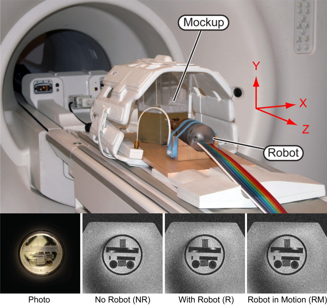
A mockup was built to simulate endorectal access to a “prostate” structure showing fine geometric patterns of lines and circles (Braino MRI test phantom). This was embedded within a gelatin base and placed in a plastic container (Figure 10). Several tests were conducted to establish a quantitative image deterioration metric [13] due to the presence of the robot in the imaging field (EP - passive test) and by the motion of the robotic instrument (EA - active test). The values of these measures range between 0% which corresponds to no deterioration and 100% which corresponds to total degradation of the images. Measures EP ≤ 2% and EA ≤ 1% are associated with unobservable image interference.
Figure 10.
In-vitro test setup in the MRI, photo of fine geometric pattern mockup located in a gelatin base, and MRI
Two sets of the following experiments were performed in a 3-Tesla scanner to calculate the image deterioration factors as well as signal to noise ratio (SNR):
Sets NR: Reference image of the mockup without the robot.
Sets R: Image of the mockup with the robot in place, powered, but not in motion.
Sets RM: Image of the mockup with the robot in motion.
The change in SNR due to the presence and motion of the robot in the imaging field have been calculated using the NEMA standard [40]. The two image sets acquired for each case (NR1 & NR2, R1 & R2, RM1 & RM2) were used. Coronal (ZX plane, Figure 10) slices were used in this evaluation. A rectangular region of interest (ROI) was defined to entirely include the geometric pattern. The signal was calculated as the average pixel values, and noise was calculated as the standard deviation of the difference between the respective sets divided by [40].
All images were acquired with a pelvic phased-array coil. The built-in coil was removed in this experiment because it was impossible to consistently acquire the NR sets.
In-vitro Image-Guided Needle Targeting Tests
Robot-assisted image-guided targeting tests have been performed with the MRI but also with the CT for its typically higher out-of-plane resolution. The measurement of the inserted needle location in the MRI is difficult due to typical artifacts at the needle point [41]. To avoid these, we placed small cylindrical ceramic markers (seeds) through the trocar and retracted the needle. The implanted seed then marked the actual targeting point. The seeds were implanted as carefully as possible to reduce seed implantation (migration) errors.
A direct targeting approach was used [42]. A mockup was made with 16 O-rings (rubber, 5.0mm inner diameter) embedded in a gelatin base. The center of each O-ring was targeted under MRI guidance and a seed was implanted. After implanting all seeds, the mockup was imaged with CT. The targeting error vector was defined as the difference between the O-ring and seed centers, in a three dimensional (3-D) reconstruction of the CT images.
To exclude errors that may have been caused by seed migration, we performed the experiment under CT-guidance and imaged the needle point directly, without the seeds. Twenty four points were targeted with the needle point. Error vectors were defined as the difference between the target and needle point in the image space.
Animal Study
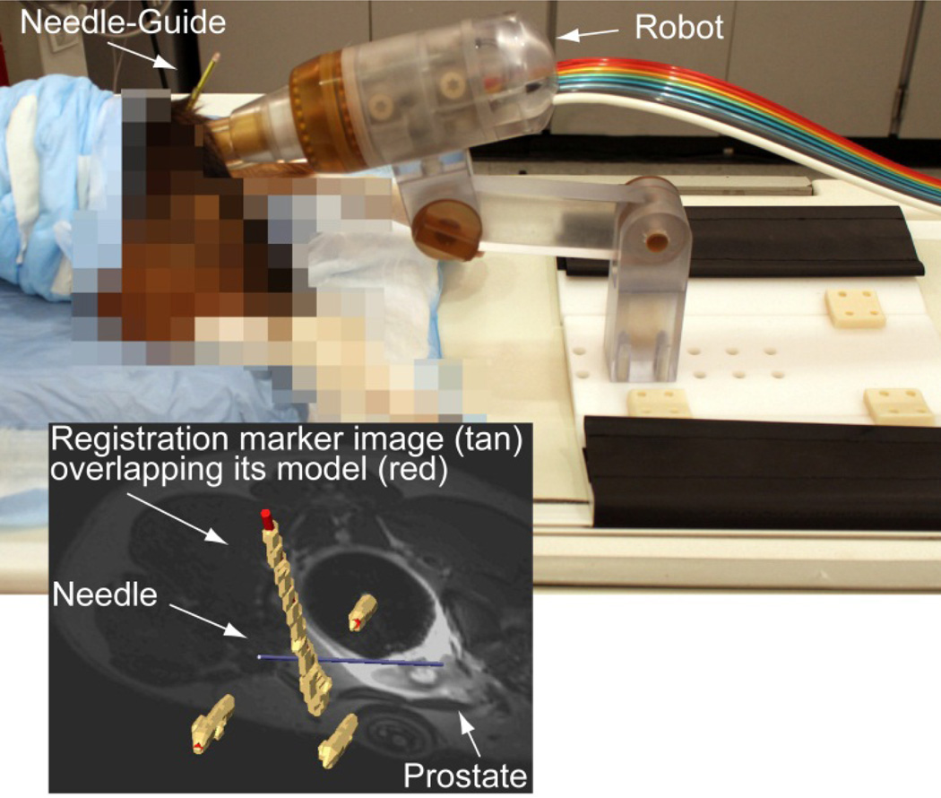
A survival animal study on 6 male Beagle dogs was performed with the approval of the Institutional Animal Care and Use Committee (IACUC) and clearance of the DoD Animal Care and Use Review Office (ACURO). Under general anesthesia, the dogs were placed prone on the MRI table on support pads (Figure 11). The endorectal extension of the robot was placed transrectally and the robot locked in place. The built-in endorectal and pelvic phased-array coils were used concurrently. Images of the marker were used for registration. Images of the prostate were used to select targets. Targeting error vectors were calculated as the difference between the target and actual locations in the image space.
Figure 11.
MRI-guided biopsy, animal experiment
VIII. Experiment Results
The results of the precision and accuracy tests are summarized in Table 2.
Table 2.
Summary of robot precision and accuracy
| Precision [mm] |
Accuracy [mm] |
|
|---|---|---|
| Bench tests | 0.17 | 0.37 |
| CT-guided, in vitro | 0.33 | 1.10 |
| MRI-guided, in vitro | 1.32 | 2.09 |
| MRI-guided, animal | 1.31 | 2.58 |
MRI Test Results
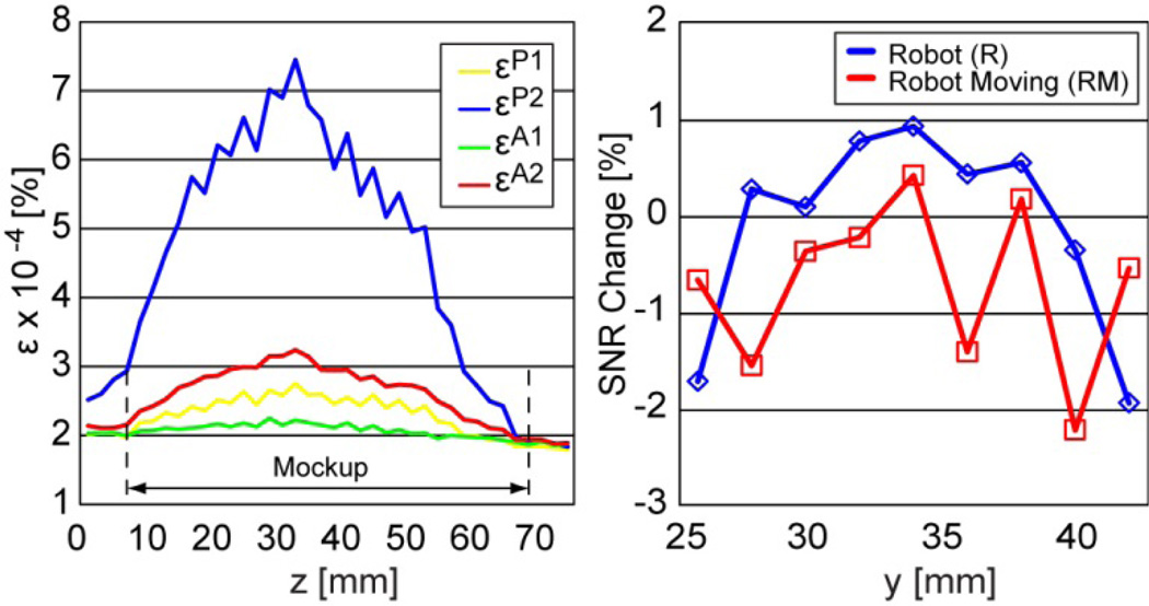
Images of the geometric pattern (Figure 10) show unperceivable differences between the NR, R, and RM sets. Figure 12 depicts the passive (P) and active (A) coefficients as a function of the axial (XY Plane, Figure 10) image slice from the mockup towards the endorectal part.
Coefficient εP1 plots differences between two sets taken without the robot (NR1-NR2).
Coefficient εP2 plots differences between two sets taken without and with the robot (NR1-R1).
Coefficient εA1 plots differences between two sets taken with the robot (R1-R2).
Coefficient εA2 plots differences between two sets taken with the robot and with the moving robot (R1-RM1).
Figure 12.
MRI deterioration factors (ε) and SNR change due to the presence and motion of the robot
The average difference between εP2 and εP1 over the geometric mockup gives the passive image deterioration factor EP, and respectively the average difference between εA2 and εA1 plots gives the active factor EA. Their experimental values are EP=2.53×10⁻⁴% and EA=5.68×10⁻⁵%.
The plots in Figure 12 also show the change in SNR due to the presence (R) and motion (RM) of the robot, relative to the no robot (NR) case. The graphs show very small positive and negative changes. In average the SNR change due to the robot is −0.1% and due to its motion −0.71% (negative is loss). Since there is no reason to believe that the presence of the robot in the imaging field enhances the quality of the images, we estimate that the fluctuations shown in the graph are due to experimental measurement errors and that the SNR change is very small, virtually zero.
Animal Study
Due to the small size of the prostate in dogs, only 4–6 targets were selects for each dog. These were targeted with the needle and MRI was acquired to measure the actual locations. Figure 11 shows an example of the image navigation screen showing the superimposed registration markers (tan-image over red-model), the prostate and the inserted needle model. Accuracy and precision data for a total of 30 targets in six dogs are included in Table 2. All dogs recovered and have been adopted.
IX. Discussion and Conclusion
We report the development of an MRI-Safe robot for endorectal direct MRI-guided biopsy. Biopsy targeting with accurate CSR targeting has the potential to 1) reduce the randomness that yields clinically insignificant cancer and leads to overdiagnosis and overtreatment, and 2) increase the likelihood of sampling the most advanced CSR reducing the underdiagnosis of potentially lethal cancer.
The robot was entirely built of nonmagnetic and electrically nonconductive materials, is electricity free, and a control structure devised according to MRI safety considerations was used. On a scientific based rationale the robot is MRI-Safe according to ASTM F2052, F2213, and F2182. In addition, imaging tests described in Sections VII and VIII make the device MRI-Safe under ASTM F2119. In conclusion, the robot is MRI-Safe under ASTM F2503 and is labeled accordingly, as shown in Figure 8.
Few MRI-Safe motorized devices exist. These include our previous MRI robot for transperineal needle access [30], the device recently developed in the Netherlands [27], and the robot reported herein. Other may only qualify as MRI-Conditional, due to the use of metals [22–25] and electricity [16–18]. This does not mean that they can’t become effective clinical tools, but more comprehensive tests will be required for regulatory clearances (FDA, European Community, and other) and their application will be restricted to specified MR environments and specified conditions of use.
But most importantly, the level of image interference for MRI-Safe and MRI-Conditional devices is substantially different, inherently, by the nature of the materials and energies used. For example, a similar kinematics robot for prostate biopsy was recently reported [18]. The primary difference is that it uses piezoelectric motors. They report up to 80% SNR loss by simply activating the motors, without motion. Even when the robot was wrapped in a shielding cloth the SNR loss was still 40% to 60%. These could potentially be improved with special drivers and additional shielding [20]. Of course, the device could be totally shut down during imaging but this creates additional problems and may raise safety concerns related to the unsupervised device and rebooting at the same location. Alternatively, with an MRI-Safe device image interference is at a different order of magnitude. For example, we measured 0.1% loss due to the robot and 0.71% due to motion, values including experimental measurement errors. The SNR loss due to MRI-Safe devices may be very small, virtually zero.
Moreover, we also show that images are not worse even with the robot in motion. In general, any device placed in the MRI will interfere, but the level is highly depended on the material types [12, 14]. Scientifically, since PCa imaging is still under development, it is preferable that no image loss or artifact should compromise the images. And, imaging should not be limited to certain sequences just to satisfy the MRI-conditional device requirement. For these multiple reasons, MRI-Safe devices are likely preferable.
MRI compatibility is often tested solely based on the SNR tests [40]. But, this test is not entirely comprehensive as it may be insensitive to image artifacts [12–14]. For example, the signal part of the SNR, which is calculated by the average pixel values in the ROI, may not be influenced by a warping artifact entirely included within the ROI. Moreover, the SNR test alone is insufficient for the FDA required ASTM F2119 test. Additional tests are required, have been proposed, and used [13, 14]. Our tests on a special MRI mockup with fine structures show that the deterioration of the images [13] due to the presence and motion of the MRI-Safe device are unperceivable.
The precision and accuracy of the robot has been tested comprehensively, first by itself, then with CT, and also with MRI, with results no larger than 2.58mm. These values are certainly within the 5mm acceptable error required to target a clinically significant tumor (0.5 cm3, 5mm radius if spherical) [43, 44].
We also report a depth of needle insertion setting method and a novel remote-DoF to implement it. With previous devices the depth has been commonly set manually and targeting errors in the direction of the needle were not reported [18]. For biopsy procedures such small errors may not be critical due to the length of the biopsy core slot. But having the depth automated simplifies the procedure, may reduce targeting errors, and could be important and safer in certain procedures.
Details regarding the image registration, navigation, and animal experiments with the MRI-Safe robot are reported in a more clinically oriented publication [45]. Here, we report the technical mechatronic development and a comprehensive set of preclinical tests. These demonstrate a novel MRI-Safe device and that this is sufficiently accurate to guide needle placement for prostate biopsy. Future work is dedicated to the FDA clearance of the device and clinical trials.
Acknowledgments
The project described was supported by Award Number W81XWH0810221 from the Prostate Cancer Research Program of the Department of Defense. The content is solely the responsibility of the authors and does not necessarily represent the official views of the PCRP or the DOD.
Biographies

Dan Stoianovici (ASME M’1994) received the Ph.D. degree from Southern Methodist University, Dallas, TX, in 1996. He is Professor of Urology, Mechanical Engineering, and Neurosurgery at the Johns Hopkins University. He is also the Director of the Urology_Robotics_Program. His specialty is medical robotics in particular robotic hardware and image-guided robots. His bibliography includes numerous publications and 20 patents of invention. He serves on the editorial boards of the IEEE/ASME TRANSACTIONS on Mechatronics, Journal of Endourology, International Journal of Medical Robotics and Computer Aided Surgery, the British Journal of Urology International and other medical-engineering journals.

Chunwoo Kim (S’2010) received a B.S. degree from Department of Mechanical Aerospace Engineering at Seoul National University in 2008. Since 2008, he is Ph.D. student in Urology Robotics Lab at Johns Hopkins University. He is a recipient of the Fulbright scholarship and the Prostate Cancer Research Training Award of the United States Department of Defense. His research interests include image-guided robots and medical imaging.

Govindarajan Srimathveeravalli received his MS and PhD degrees in mechanical engineering from University at Buffalo, Buffalo, NY. After a brief stint in the industry he returned to academic research as a postdoctoral fellow with Memorial Sloan-Kettering Cancer Center. Currently he is an Assistant Attending Engineer with Memorial Sloan-Kettering Cancer Center, and an Assistant Professor with Dept. of Radiology in Weil Cornell Medical College. His specialty is in developing tools and devices that enable minimally invasive image guided therapy of oncologic conditions. For this, he has developed robotic systems that provide endovascular access, and training tools for improving surgical skill while performing robot assisted surgery. He is currently studying the biological impact of different types of energy that are used for tissue ablation.

Doru Petrisor (ASME M’2003) received a MS degree in Mechanical Engineering from the University of Craiova, Romania in 1988, the PhD from the University of Petrosani, Romania in 2002, followed by a research fellowship in Urology at the Johns Hopkins University. Between 1991–1994 he was Assistant Professor at the University of Craiova and Lecturer since 1994. In 2002 he joined the Urology Robotics research group at Johns Hopkins and currently is Research Associate Professor. Dr. Petrisor's specialty is design of interventional and surgical robots, medical instrumentation, and CNC manufacturing. His bibliography includes numerous articles, presentations, and 4 patents of invention.

Stephen B. Solomon received his M.D. degree from Yale University School of Medicine, New Haven CT in 1993. He is Professor of Radiology at Weill Cornell Medical College. He is also the Chief of Interventional Radiology at Memorial Sloan-Kettering Cancer Center in New York. His specialty is image-guided interventions. He has over 100 peer-reviewed publications.

Hedvig Hricak received her MD from the University of Zagreb in Zagreb, Croatia and her Dr. Med. Sc. (PhD) from the Karolinska Institute in Stockholm, Sweden. She is Chair of the Department of Radiology at Memorial Sloan-Kettering Cancer Center (MSKCC). She holds a senior position within the Program of Molecular Pharmacology and Chemistry at the Sloan-Kettering Institute, is a professor at Gerstner Sloan-Kettering Graduate School of Biomedical Sciences, and is a professor of radiology at the Weill Medical College of Cornell University. In 2005 she was awarded an honorary doctorate in medicine from Ludwig Maximilian University in Munich, Germany. Before joining MSKCC, she was a professor of radiology, radiation oncology, urology and gynecology at the University of California at San Francisco and headed the abdominal section of the Department of Radiology at UCSF Medical Center. The focus of Dr. Hricak’s research is the development and validation of imaging biomarkers for improving the detection, diagnosis and evidence-based management of gynecological and genitourinary cancers. She and her group have developed applications of cross-sectional imaging techniques (e.g., ultrasound, MRI, CT) and as well as molecular imaging techniques (e.g., DCE-MRI, MR spectroscopy, and PET/CT and PET/MRI with innovative tracers). Dr. Hricak is a member of the Institute of Medicine of the National Academies of Science. Dr. Hricak has authored or co-authored 367 peer-reviewed original research articles, 185 review/editorial articles, and 145 book chapters. She has given more than 130 named or keynote lectures and has been a visiting professor at more than 30 institutions worldwide.
REFERENCES
- 1.Siegel R, Naishadham D, Jemal A. Cancer statistics, 2013. CA Cancer J Clin. 2013;63:11–30. doi: 10.3322/caac.21166. [DOI] [PubMed] [Google Scholar]
- 2.Barry MJ. Screening for prostate cancer--the controversy that refuses to die. N Engl J Med. 2009;360:1351–1354. doi: 10.1056/NEJMe0901166. [DOI] [PubMed] [Google Scholar]
- 3.Han M, Chang D, Kim C, Lee BJ, Zuo Y, Kim HJ, Petrisor D, Trock B, Partin AW, Rodriguez R, Carter HB, Allaf M, Kim J, Stoianovici D. Geometric Evaluation of Systematic Transrectal Ultrasound Guided Prostate Biopsy. Journal of Urology. 2012;188:2404–2409. doi: 10.1016/j.juro.2012.07.107. http://urobotics.urology.jhu.edu/pub/2012-han-jurol.pdf. [DOI] [PMC free article] [PubMed] [Google Scholar]
- 4.Kelloff GJ, Choyke P, Coffey DS. Challenges in clinical prostate cancer: role of imaging. AJR Am J Roentgenol. 2009;192:1455–1470. doi: 10.2214/AJR.09.2579. [DOI] [PMC free article] [PubMed] [Google Scholar]
- 5.Hricak H, Choyke PL, Eberhardt SC, Leibel SA, Scardino PT. Imaging prostate cancer: a multidisciplinary perspective. Radiology. 2007;243:28–53. doi: 10.1148/radiol.2431030580. [DOI] [PubMed] [Google Scholar]
- 6.Yang EY, Polsani VR, Washburn MJ, Zang W, Hall AL, Virani SS, Hodge MD, Parker D, Kerwin WS, Lawrie GM, Garami Z, Ballantyne CM, Morrisett JD, Nambi V. Real-time co-registration using novel ultrasound technology: ex vivo validation and in vivo applications. J Am Soc Echocardiogr. 2011;24:720–728. doi: 10.1016/j.echo.2011.02.003. [DOI] [PMC free article] [PubMed] [Google Scholar]
- 7.Cheung MR, Krishnan K. Using manual prostate contours to enhance deformable registration of endorectal MRI. Comput Methods Programs Biomed. 2012 doi: 10.1016/j.cmpb.2012.01.009. [DOI] [PubMed] [Google Scholar]
- 8.Xu S, Kruecker J, Turkbey B, Glossop N, Singh AK, Choyke P, Pinto P, Wood BJ. Real-time MRI-TRUS fusion for guidance of targeted prostate biopsies. Comput Aided Surg. 2008;13:255–264. doi: 10.1080/10929080802364645. [DOI] [PMC free article] [PubMed] [Google Scholar]
- 9.Shigemura K, Motoyama S, Yamashita M. Do additional cores from MRI cancer-suspicious lesions to systematic 12-core transrectal prostate biopsy give better cancer detection? Urol Int. 2012;88:145–149. doi: 10.1159/000334375. [DOI] [PubMed] [Google Scholar]
- 10.Beyersdorff D, Winkel A, Hamm B, Lenk S, Loening SA, Taupitz M. MR imaging-guided prostate biopsy with a closed MR unit at 1.5 T: initial results. Radiology. 2005;234:576–581. doi: 10.1148/radiol.2342031887. [DOI] [PubMed] [Google Scholar]
- 11.Susil RC, Menard C, Krieger A, Coleman JA, Camphausen K, Choyke P, Fichtinger G, Whitcomb LL, Coleman CN, Atalar E. Transrectal prostate biopsy and fiducial marker placement in a standard 1.5T magnetic resonance imaging scanner. J Urol. 2006;175:113–120. doi: 10.1016/S0022-5347(05)00065-0. [DOI] [PMC free article] [PubMed] [Google Scholar]
- 12.El Bannan K, Handler WB, Wyenberg C, Chronik BA, Salisbury SP. Prediction of Force and Image Artifacts Under MRI for Metals Used in Medical Devices. IEEE/ASME TRANSACTIONS ON MECHATRONICS. 2012;18:954–962. [Google Scholar]
- 13.Stoianovici D. Multi-Imager Compatible Actuation Principles in Surgical Robotics. International Journal of Medical Robotics and Computer Assisted Surgery. 2005;1:86–100. doi: 10.1002/rcs.19. http://urobotics.urology.jhu.edu/pub/2005-stoianovici-MRCASJ.pdf. [DOI] [PMC free article] [PubMed] [Google Scholar]
- 14.Yu N, Gassert R, Riener R. Mutual interferences and design principles for mechatronic devices in magnetic resonance imaging. Int J Comput Assist Radiol Surg. 2011;6:473–488. doi: 10.1007/s11548-010-0528-2. [DOI] [PubMed] [Google Scholar]
- 15.Gassert R, Moser R, Burdet E, Bleuler H. MRI/fMRI-compatible robotic system with force feedback for interaction with human motion. Ieee-Asme Transactions on Mechatronics. 2006;11:216–224. [Google Scholar]
- 16.Wang Y, Cole GA, Su H, Pilitsis JG, Fischer GS. MRI compatibility evaluation of a piezoelectric actuator system for a neural interventional robot. Conf Proc IEEE Eng Med Biol Soc. 2009;2009:6072–6075. doi: 10.1109/IEMBS.2009.5334206. [DOI] [PubMed] [Google Scholar]
- 17.Su H, Camilo A, Cole GA, Hata N, Tempany CM, Fischer GS. High-field MRI-compatible needle placement robot for prostate interventions. Stud Health Technol Inform. 2011;163:623–629. [PMC free article] [PubMed] [Google Scholar]
- 18.Krieger A, Song SE, Cho NB, Iordachita I, Guion P, Fichtinger G, Whitcomb LL. Development and Evaluation of an Actuated MRI-Compatible Robotic System for MRI-Guided Prostate Intervention. IEEE ASME Trans Mechatron. 2012;18:273–284. doi: 10.1109/TMECH.2011.2163523. [DOI] [PMC free article] [PubMed] [Google Scholar]
- 19.Wendt O, Oellinger J, Luth TC, Felix R, Boenick U. The effects of the use of piezoelectric motors in a 1.5-Tesla high-field magnetic resonance imaging system (MRI) Biomedizinische Technik. 2000;45:20–25. doi: 10.1515/bmte.2000.45.1-2.20. [DOI] [PubMed] [Google Scholar]
- 20.Fischer GS, Cole G, Su H. Approaches to creating and controlling motion in MRI. Conf Proc IEEE Eng Med Biol Soc. 2011;2011:6687–6690. doi: 10.1109/IEMBS.2011.6091649. [DOI] [PubMed] [Google Scholar]
- 21.Taylor RH, Stoianovici D. Medical robotics in computer-integrated surgery. IEEE Transactions on Robotics and Automation. 2003;19:765–781. http://urobotics.urology.jhu.edu/pub/2003-taylor-ieeetra.pdf. [Google Scholar]
- 22.van den Bosch MR, Moman MR, van Vulpen M, Battermann JJ, Duiveman E, van Schelven LJ, de Leeuw H, Lagendijk JJ, Moerland MA. MRI-guided robotic system for transperineal prostate interventions: proof of principle. Phys Med Biol. 2010;55:N133–N140. doi: 10.1088/0031-9155/55/5/N02. [DOI] [PubMed] [Google Scholar]
- 23.Tokuda J, Song SE, Fischer GS, Iordachita, Seifabadi R, Cho NB, Tuncali K, Fichtinger G, Tempany CM, Hata N. Preclinical evaluation of an MRI-compatible pneumatic robot for angulated needle placement in transperineal prostate interventions. Int J Comput Assist Radiol Surg. 2012 doi: 10.1007/s11548-012-0750-1. [DOI] [PMC free article] [PubMed] [Google Scholar]
- 24.Fischer GS, Iordachita I, Csoma C, Tokuda J, Dimaio SP, Tempany CM, Hata N, Fichtinger G. MRI-Compatible Pneumatic Robot for Transperineal Prostate Needle Placement. IEEE ASME Trans Mechatron. 2008;13:295–305. doi: 10.1109/TMECH.2008.924044. [DOI] [PMC free article] [PubMed] [Google Scholar]
- 25.Song SE, Hata N, Iordachita I, Fichtinger G, Tempany C, Tokuda J. A workspace-orientated needle-guiding robot for 3T MRI-guided transperineal prostate intervention: evaluation of in-bore workspace and MRI compatibility. Int J Med Robot. 2012 doi: 10.1002/rcs.1430. [DOI] [PMC free article] [PubMed] [Google Scholar]
- 26.Zangos S, Herzog C, Eichler K, Hammerstingl R, Lukoschek A, Guthmann S, Gutmann B, Schoepf UJ, Costello P, Vogl TJ. MR-compatible assistance system for punction in a high-field system: device and feasibility of transgluteal biopsies of the prostate gland. Eur Radiol. 2007;17:1118–1124. doi: 10.1007/s00330-006-0421-0. [DOI] [PubMed] [Google Scholar]
- 27.Schouten MG, Ansems J, Renema WK, Bosboom D, Scheenen TW, Futterer JJ. The accuracy and safety aspects of a novel robotic needle guide manipulator to perform transrectal prostate biopsies. Med Phys. 2010;37:4744–4750. doi: 10.1118/1.3475945. [DOI] [PubMed] [Google Scholar]
- 28.Yakar D, Schouten MG, Bosboom DG, Barentsz JO, Scheenen TW, Futterer JJ. Feasibility of a pneumatically actuated MR-compatible robot for transrectal prostate biopsy guidance. Radiology. 2011;260:241–247. doi: 10.1148/radiol.11101106. [DOI] [PubMed] [Google Scholar]
- 29.Stoianovici D, Patriciu A, Mazilu D, Petrisor D, Kavoussi L. A New Type of Motor: Pneumatic Step Motor. IEEE/ASME TRANSACTIONS ON MECHATRONICS. 2007;12:98–106. doi: 10.1109/TMECH.2006.886258. 2008 Best Paper Award of the Journal, http://urobotics.urology.jhu.edu/pub/2007-stoianovici-tmech.pdf. [DOI] [PMC free article] [PubMed] [Google Scholar]
- 30.Stoianovici D, Song D, Petrisor D, Ursu D, Mazilu D, Muntener M, Schar M, Patriciu A. “MRI Stealth” Robot for Prostate Interventions. Minimally Invasive Therapy & Allied Technologies. 2007;16:241–248. doi: 10.1080/13645700701520735. http://urobotics.urology.jhu.edu/pub/2007-stoianovici-mitat.pdf. [DOI] [PMC free article] [PubMed] [Google Scholar]
- 31.Muntener M, Patriciu A, Petrisor D, Mazilu D, Kavoussi L, Cleary K, Stoianovici D. Magnetic Resonance Imaging Compatible Robotic System for Fully Automated Brachytherapy Seed Placement. Urology. 2006;68:1313–1317. doi: 10.1016/j.urology.2006.08.1089. http://urobotics.urology.jhu.edu/pub/2006-muntener-urology.pdf. [DOI] [PMC free article] [PubMed] [Google Scholar]
- 32.Muntener M, Patriciu A, Petrisor D, Schar M, Ursu D, Song D, Stoianovici D. Transperineal prostate intervention: robot for fully automated MR imaging--system description and proof of principle in a canine model. Radiology. 2008;247:543–549. doi: 10.1148/radiol.2472070737. http://urobotics.urology.jhu.edu/pub/2008-muntener-radiology.pdf. [DOI] [PMC free article] [PubMed] [Google Scholar]
- 33.Krieger A, Susil RC, Menard C, Coleman JA, Fichtinger G, Atalar E, Whitcomb LL. Design of a novel MRI compatible manipulator for image guided prostate interventions. IEEE Trans Biomed Eng. 2005;52:306–313. doi: 10.1109/TBME.2004.840497. [DOI] [PMC free article] [PubMed] [Google Scholar]
- 34.Krieger A, Csoma C, Iordachital, Guion P, Singh AK, Fichtinger G, Whitcomb LL. Design and preliminary accuracy studies of an MRI-guided transrectal prostate intervention system. Med Image Comput Comput Assist Interv. 2007;10:59–67. doi: 10.1007/978-3-540-75759-7_8. [DOI] [PMC free article] [PubMed] [Google Scholar]
- 35.Han M, Kim C, Mozer P, Schafer F, Badaan S, Vigaru B, Tseng K, Petrisor D, Trock B, Stoianovici D. Tandem-robot Assisted Laparoscopic Radical Prostatectomy to Improve the Neurovascular Bundle Visualization: A Feasibility Study. Urology. 2011;77:502–506. doi: 10.1016/j.urology.2010.06.064. http://urobotics.urology.jhu.edu/pub/2011-han-urology.pdf. [DOI] [PMC free article] [PubMed] [Google Scholar]
- 36.Stoianovici D, Kim C, Schafer F, Huang CM, Zuo YH, Petrisor D, Han M. Endocavity Ultrasound Probe Manipulators. IEEE/ASME TRANSACTIONS ON MECHATRONICS. 2013;18:914–921. doi: 10.1109/TMECH.2012.2195325. http://urobotics.urology.jhu.edu/pub/2013-stoianovici-tmech.pdf. [DOI] [PMC free article] [PubMed] [Google Scholar]
- 37.Kanal E, Barkovich AJ, Bell C, Borgstede JP, Bradley WG, Jr., Froelich JW, Gilk T, Gimbel JR, Gosbee J, Kuhni-Kaminski E, Lester JW, Jr., Nyenhuis J, Parag Y, Schaefer DJ, Sebek-Scoumis EA, Weinreb J, Zaremba LA, Wilcox P, Lucey L, Sass N. ACR guidance document for safe MR practices: 2007. AJR Am J Roentgenol. 2007;188:1447–1474. doi: 10.2214/AJR.06.1616. [DOI] [PubMed] [Google Scholar]
- 38.Decker R, Jun C, Vacharat A, Taylor HR, Stoianovici D. How to use an Optical Tracker for more Accurate Measurements. presented at Engineering and Urology Society, 27th Annual Meeting; Atlanta, GA. 2012. http://engineering-urologyorg/am/27EUS_2012pdf. [Google Scholar]
- 39.Arun KS, Huang TS, Blostein SD. Least-squares fitting of two 3-d point sets. IEEE Trans Pattern Anal Mach Intell. 1987;9:698–700. doi: 10.1109/tpami.1987.4767965. [DOI] [PubMed] [Google Scholar]
- 40.NEMA Standards Publication MS 1-2008. 2008. Determination of Signal-to-Noise Ratio (SNR) in Diagnostic Magnetic Resonance Imaging. N. E. M. Association, Ed., www.nema.org. [Google Scholar]
- 41.Song SE, Cho NB, Iordachita, Guion P, Fichtinger G, Kaushal A, Camphausen K, Whitcomb LL. Biopsy Needle Artifact Localization in MRI-Guided Robotic Transrectal Prostate Intervention. IEEE Trans Biomed Eng. 2012;59:1902–1911. doi: 10.1109/TBME.2012.2192118. [DOI] [PMC free article] [PubMed] [Google Scholar]
- 42.Kim C, Chang D, Petrisor D, Chirikjian G, Han M, Stoianovici D. Ultrasound probe and needle-guide calibration for robotic ultrasound scanning and needle targeting. IEEE Transactions on Biomedical Engineering. 2013;60:1728–1734. doi: 10.1109/TBME.2013.2241430. http://urobotics.urology.jhu.edu/pub/2013-kim-tbme.pdf. [DOI] [PubMed] [Google Scholar]
- 43.Ploussard G, Epstein JI, Montironi R, Carroll PR, Wirth M, Grimm MO, Bjartell AS, Montorsi F, Freedland SJ, Erbersdobler A, van der Kwast TH. The contemporary concept of significant versus insignificant prostate cancer. Eur Urol. 2011;60:291–303. doi: 10.1016/j.eururo.2011.05.006. [DOI] [PubMed] [Google Scholar]
- 44.Stamey TA, Freiha FS, McNeal JE, Redwine EA, Whittemore AS, Schmid HP. Localized prostate cancer. Relationship of tumor volume to clinical significance for treatment of prostate cancer. Cancer. 1993;71:933–938. doi: 10.1002/1097-0142(19930201)71:3+<933::aid-cncr2820711408>3.0.co;2-l. [DOI] [PubMed] [Google Scholar]
- 45.Srimathveeravalli G, Kim C, Petrisor D, Ezell P, Coleman J, Hricak H, Solomon S, Stoianovici D. MRI-Safe Robot for Targeted Transrectal Prostate Biopsy: Animal Experiments. British Journal of Urology International. 2013 doi: 10.1111/bju.12335. pp. in press. [DOI] [PubMed] [Google Scholar]


