

Abstract
The rapid growth of the brain in the first few years of life drives the expansion of the cranial vault. This expansion occurs primarily at the cranial sutures; premature fusion of these results in growth restriction perpendicular to the axis of the suture. The result of this is physical deformation of the cranial and facial skeleton, as well as the distortion of the underling brain and its physiology. These patients can present with symptoms of raised intracranial pressure, neurodevelopmental delay, as well as the morphological features of craniosynostosis. Acquired conditions such as the slit ventricle syndrome may also result in cephalocranial disproportion with these clinical features. Traditional vault remodeling surgery is able to correct the physical abnormalities as well as correcting cephalocranial disproportion. Its limitations include the degree of scalp expansion achievable as well as resulting defects in the bone. The use of distraction osteogenesis of the cranial vault permits a controlled expansion in a predetermined vector in a gradual manner. When used in the calvarium, this combines the benefits of tissue expansion on the scalp, as well as stimulating the production of new bone, reducing the defects resulting from expansion.
In this review, the authors describe some of the surgical considerations important to the use of this technique. This includes the relevant anatomy and technical aspects illustrated with the use of clinical cases. Finally, they present a summary of their experience and discuss the complications associated with cranial vault distraction osteogenesis.
Keywords: osteogenesis, distraction osteogenesis, posterior cranial vault expansion, craniosynostosis, syndromic craniosynostosis, distraction devices
Craniosynostosis is the premature fusion of the calvarial sutures. Although many of these sutures do not close until the second or third decades of life, the greatest clinical impact occurs when sutures fuse during the period of rapid brain growth in the first few years of life. The result of the premature closure of these sutures, results in the restriction of calvarial growth perpendicular to the axis of the suture (Virchow's law) and compensatory expansion elsewhere to accommodate the rapidly growing brain. The clinical consequences of this are physical distortions of the craniofacial skeleton, causing both localized pressure on the underlying brain as well as increasing the risk of raised intracranial pressure (ICP).
The aims of treatment of patients with single-suture synostosis are directed toward removing the restrictions of the synostotic suture, to allow unrestricted growth of the brain, and expansion of the calvarial volume to accommodate the growing brain and to prevent or correct any craniofacial distortions.
Most patients with nonsyndromic, single-suture craniosynostoses will present during infancy with anomalies detected in cranial shape. Traditional vault remodeling can be used as a single procedure to correct their cranial shape. This is commonly performed around the age of 8 to 10 months when the cranial bone has calcified sufficiently, yet retains enough plasticity to be surgically remodeled.
Patients with multisutural craniosynostosis and syndromic craniosynostosis present with other competing clinical issues in addition to abnormal craniofacial form. The overall risk of raised ICP is increased with the number of sutures involved and is higher in syndromic craniosynostosis.1 In addition, these challenging patients often require multiple, function-preserving interventions to address the airway obstruction, treat exorbitism and to correct facial form in addition to cephalocranial disproportion and morphology. Timing of these procedures in relation to necessity and development is crucial and demands an individualized approach to each patient throughout his or her life.
Traditional cranial vault remodeling addresses the cranial volume and cranial morphology adequately, but has some significant limitations. Volume expansion is limited by the capacity for the scalp to stretch over the expanded calvarial construct. In addition, the separation of the calvarium from the dura creates a construct of devascularized bone with defects as a result of an expanded volume. In infants, this bone construct usually heals without any residual significant defects; however, older children progressively lose this capacity beyond the age of 12 to 14 months. The reconstruction of these resultant bony defects requires creating a secondary donor site with its attendant morbidity.
Distraction osteogenesis (first used in the craniofacial skeleton by McCarthy to lengthen the mandible2) has been shown to be able to resolve some of these challenges elsewhere in the craniofacial skeleton.
The expansion of the fronto-orbital skeleton by distraction was able to address the anterior cranial volume as well as the retruded orbital bandeau.3 4 5 6 7 However, the degree of cranial volume expansion is limited by globe to orbit proportion.
The introduction of distraction to expand the posterior calvarium8 addressed many of these shortcomings. It permitted the scalp to be closed without tension and facilitated a controlled expansion. In addition, it obviated the need for secondary bone grafting of the residual bony defect. In children normally nursed in a supine position, it also resists relapse associated with pressure on the occipital region prior to bone union. Furthermore, posterior expansion has the capacity to achieve 35% more volume expansion when compared with an equivalent movement by anterior vault expansion.9
Furthermore, unlike anterior vault distraction, posterior expansion of the cranium appears to decrease the frontal bossing and to decrease cranial height trajectory.10 These beneficial cranial morphological changes permit any frontofacial surgery to be addressed independently at the appropriate time. In addition, expansion of the posterior vault reduces tonsillar herniation in some patients.11
Despite these advantages, several complications related to the technique have been reported. Dural injury, device failure and loosening, infection and wound dehiscence were all reported in the initial study by White et al. 8 Posterior vault distraction osteogenesis may be associated with reduced operative duration, transfusion requirements, and hospital stays.12 However, this finding is not universal with others reporting little difference in the perioperative and safety profiles of distraction osteogenesis when compared with conventional vault remodeling.13
Method
Preoperative Surgical Planning
There are several critical components in the preoperative surgical planning for posterior cranial vault distraction. These goals aim to address cephalocranial disproportion by increasing cranial volume, as well as altering the shape of the cranium by careful design of the osteotomies and expansion along a predesignated vector.
Distraction Vector
In general, osteotomies are designed along a predominantly coronal plane with posterior movement vector parallel to the main anteroposterior axis of the skull. The advantage of a posterior distraction vector is that there is no impact on facial balance. There are other clinical scenarios that require variations from this design; they are listed in Table 1.
Table 1. Indications for posterior vault distraction and appropriate vector of distraction.
| Type | Indication | Vector |
|---|---|---|
| 1 | Cephalocranial disproportion with acceptable overall shape | Posterior |
| 2 | Cephalocranial disproportion with Chiari 1 malformation | Posterior with foramen magnum decompression |
| 3 | Turribrachycephaly | Posteroinferior |
| 4 | Shunt related slit ventricle syndrome | Bilateral |
| 5 | Asymmetric cranium | Asymmetrical expansion |
Degree of Distraction
The degree of volume expansion is controlled by the distance of expansion and the cross-sectional area of the cranium between the osteotomies. It follows that by placing the osteotomies at the widest point of the skull, a greater volume expansion can be achieved for each millimeter (mm) of distraction than at narrower points.
Anatomical Considerations
Clinical examination and computed tomography (CT) and magnetic resonance imaging (MRI) are an essential component of the presurgical planning. In addition to confirming the overall head shape, imaging is used to define the bony characteristics such as bone thickness, deficiencies, and perforations as well as the position and size of the fontanelles and sutures. In addition, the underlying anatomy of the venous sinuses, the volume of cerebrospinal fluid (CSF) and radiological signs of ICP are noted as well as any anomalous features that may be encountered during surgery.
In a typical posterior cranial vault expansion (Figs. 1 and 2), the general path of the initial osteotomy is in the coronal direction. At the vertex, this traverses the superior sagittal sinus that is running in an anteroposterior direction under the sagittal suture. The osteotomy continues inferiorly to a point within the squamous temporal bone near the asterion. These osteotomies running from the vertex inferiorly toward the occipital bone traverse the lateral sinus, which should be approached with great care. These osteotomies are then angled slightly more posteriorly to meet in the midline. This juncture should be at a point around the inion to reduce any appreciable step deformity at the termination of the distraction process. In the case of Chiari 1 malformation, a foramen magnum decompression (Fig. 3) can be incorporated into this osteotomy by modifying the osteotomy and directing it toward the foramen magnum at a point inferior to the asterion.
Fig. 1.
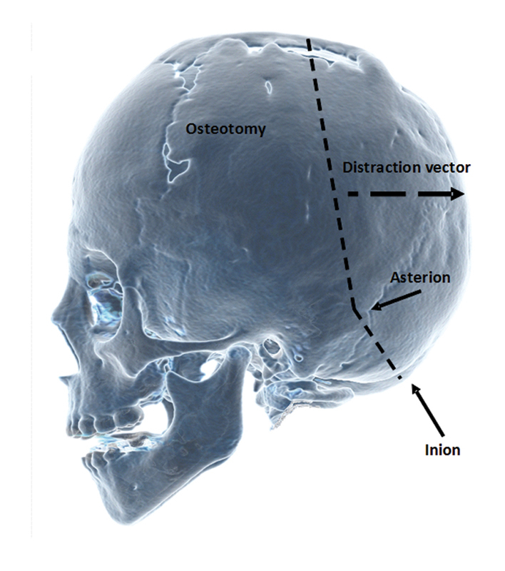
Lateral view illustrating standard osteotomies running from the vertex to a point near the asterion and ending below the inion.
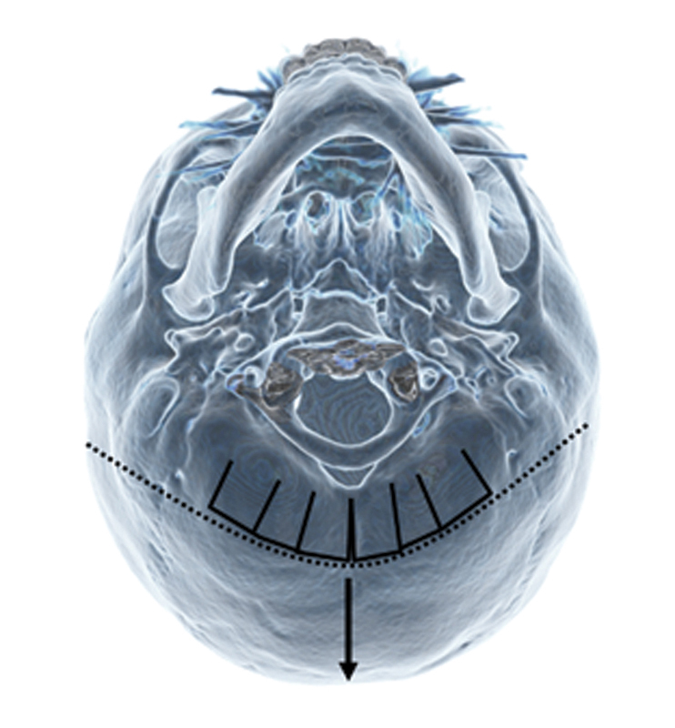
Fig. 2.
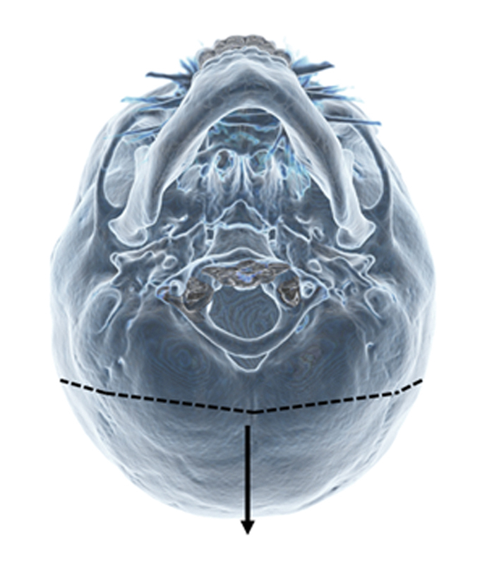
Basal view illustrating osteotomies and vector of movement. Note the osteotomies are made near the widest point on the skull.
Fig. 3.
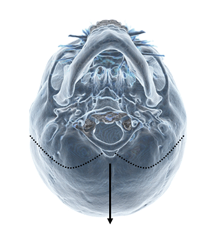
Basal view of osteotomies with a variation including a foramen magnum decompression.
Surgical Technique
Technical Tips for the Osteotomy
The patients are positioned prone. A zigzag coronal incision is made, with subgaleal dissection of anterior and posterior scalp flaps. Following pericranial elevation adequate exposure of the cranial surface is achieved. Optimal sites for the osteotomies are determined and this is correlated with CT imaging.
A matchstick burr is used to safely perforate the skull on either side of the sagittal sinus to allow the craniotome to be safely introduced to complete the osteotomies. At particularly high-risk areas, such as around the venous sinuses, the matchstick burr can be used to complete the osteotomies. There is significant variation in bone thickness, as well as in irregularity in the endocranial surface particularly when there is significant thumbprinting associated with raised ICP. Bony variation and the relation of the underlying dilated venous structures to the overlying bony landmarks require that extreme caution should be exercised at all times. The major confluence of the superior sagittal, straight sinus, and transverse sinus is an area known as the torcula. This lies at a region between the juncture of the sagittal and lambdoid sutures and the inion. This then runs laterally toward the asterion as the transverse sinus. The lateral coronal osteotomies are designed to advance across the transverse sinuses and connect in the midline at a point on the downward slope of the occipital bone inferior to the inion and torcula.
Dural Mobilization
Once the osteotomies have been made, the dura is mobilized from the cranium anterior to the osteotomy (Fig. 4). In contrast, the dura is left adhered to the posterior mobile segment. By limiting the dural release to the area under the anterior immobile cranium and preserving the dural attachments to the mobile posterior bone segment, perfusion is preserved to both components.
Fig. 4.
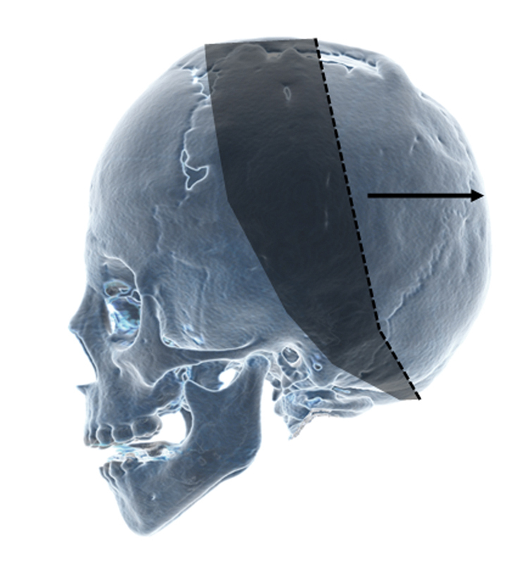
Lateral view illustrating osteotomies (dashed line) and the areas of dural mobilization (gray) and posterior vector of mobile segment (arrow).
We believe this not only preserves blood perfusion to this mobilized bone segment, but also distributes tension from the distraction process over a larger area of dura reducing the potential for tears that may result in bleeding or CSF leaks.
Reducing Step Deformity
To reduce the potential for residual step deformity, the osteotomy should be designed so that the limit of the osteotomy is inferior to the torcula, along the gentle slope toward the foramen magnum (Fig. 2). Where this may not be achievable, or when there is significant asymmetry, barrel staves in combination with outfracturing can be incorporated to reduce the potential for a step deformity (Fig. 5). In most cases, inferior barrel staves in the immobile segment of occipital bone are made with the benefit of a further increase in expansion and reducing a step-off deformity.
Fig. 5.
Location of barrel stave osteotomies to correct for step-off deformities when higher osteotomies are used.
Distractor Placement
Once the osteotomies have been made and dural mobilization performed, a meticulous examination is performed to ensure hemostasis and to identify and repair any dural tears. Prior to placement of the device, each distractor is tested by turning the screws to the full extended limit of the range and then closing the device to the starting position. Two distractors are then positioned, ensuring that the vectors of each distractor are parallel and that the footplates lie in a stable configuration on the outer table spanning the osteotomy with the positioning hooks precisely placed at the margin of the respective bone segments.
Before the footplates are secured to the underlying bone, it is important to open the distractors slightly to correctly seat the positioning hooks. This ensures that during distraction, the forces are transmitted through these hooks to the edge of the bone segments rather than borne by the securing screws.
Prevention of dural injury during osseous fixation of the distractor footplates is particularly important. Several strategies can be employed to minimize the risk of dural injury during placement of the devices as well as during distraction and removal. These strategies can be adapted according to the individual characteristics of the patient.
Self-drilling screws are used to minimize the risk of dural injury from drilling; we routinely use blunt-tipped modification of these screws to further minimize injury. Occasionally, where the bone is particularly hard, small pilot holes can be drilled to ease the entry of the self-drilling screws. When the drill is used, dural injury can be prevented by using an instrument, such as a malleable retractor placed between the dura and below the bone in the trajectory of the drill. A minimum of three screws on each hemi-footplate are required to achieve secure fixation. If the bone is particularly thin, more screws may be required.
Once the distractors have been fully secured, the device is completely closed to reapproximate the bone margins. The turning arms are fitted to the device and the scalp flaps repositioned to identify an appropriate site for the incision in the scalp to enable the distraction arms to traverse the skin without undue tension.
Once satisfied with the positioning of the distractor devices, a layered closure of the scalp over two subgaleal drains completes the surgical procedure.
Postsurgical Management
Distraction Protocol
Following surgery, patients remain in the hospital until drainage is less than 25 ml/24 h. Antibiotics are continued until the drains are removed.
The distraction protocol we employ is dependent on the age of the patient (Table 2). The latency period for children up to 6 months of age is 5 days. Between 6 months and 2 years of age, distraction commences at 7 days; for children between 2 and 8 years of age, distraction commences at 10 days. Above this age, distraction starts at 2 weeks.
Table 2. Age-adjusted distraction protocol.
| Age | Latency | Distraction rate (0.3/turn) | Distraction distance | Consolidation |
|---|---|---|---|---|
| < 6 mo | 5 d | 0.9 mm/d | 20–30 mm | 2 mo |
| 6 mo–8 y | 7 d | 0.9 mm/d | ||
| 8–16 y | 10 d | 0.6 mm/d |
In addition, the rate of distraction in governed by the age. Children up to the age of two are distracted at 1.2 mm/d, whereas children between 2 and 8 years are distracted at 0.9 mm/d and older children at 0.6 mm/d.
As we age, the rate of bone healing reduces. Our distraction protocol reflects this phenomenon in terms of increasing latency period and distraction rate. All patients undergo a 2-month period of consolidation prior to removal of the devices.
In patients without pressure symptoms, the degree of distraction is guided by the overall head shape. Parents are taught how to perform distraction that is then executed at home. Instructions regarding the appropriate care of the distractors are given and parents are advised to monitor the patient for signs of potential complications.
In some cases, it may be useful to monitor the effect of distraction on ICP using direct monitoring. In these patients, an intraparenchymal probe is placed after the initial period of distraction. The ICP is monitored for a minimum of 48 hours while distraction continues; the results of this investigation can be used to guide further distraction.
Clinical signs and symptoms of raised ICP remain the most important aspect guiding distraction. As patients often recover quickly from the surgery to place the distractors, parents often notice an improvement in the demeanor of patients as the intracranial volume increases. They often describe decreased irritability, improved feeding and playing, as well as morphological changes. As physicians, in addition to these features, we often see reduction in proptosis, reduced dilation of scalp veins, and reduced papilledema. An increased anteroposterior length reduced frontal bossing and reduced turricephaly also occur over the distraction period. Imaging shows reduced cephalocranial disproportion and a reduction in the thumbprinting associated with raised ICP.
Follow-Up
Patients are followed in the clinic on a weekly basis during the distraction period to monitor for signs of any complications. These include wound breakdown, distractor malfunction, and progression of distraction, CSF leak and infection, as well as overall shape and symptoms of raised ICP.
A low-dose craniofacial CT is performed after 2 months of consolidation to assess bony union prior to removal of the distraction device. A further low-dose CT scan and fast acquisition MRI is performed at 2 years following distraction. This time point is selected to assess whether distraction of the vault has achieved its primary aims as well as to detect and complications.
In addition to assessing overall cranial morphology, the effect of expansion on the brain is assessed and correlated with any features of raised ICP. Any residual bony defects are noted and examined to determine whether they represent a risk of reduced brain protection or as a feature of persistent ICP. Although unusual, any clinically significant bone defects are usually treated with bone grafting.
Results
Seventeen patients were treated with posterior cranial vault distraction osteogenesis over a period of 28 months (December 2009–March 2013) at our institution (Table 3). Five patients had syndromic craniosynostosis (two Crouzon, two Apert, one Pfeiffer). Thirteen of these 17 patients had multisuture craniosynostosis. Two patients had single-suture synostosis (one lambdoid and one sagittal). Two patients had shunt-related craniosynostosis.
Table 3. Patients undergoing posterior cranial vault distraction and indications for surgery.
| Patient | Condition | Sutures | Indication |
|---|---|---|---|
| 1 | Apert | Bicoronal | ICP, shape |
| 2 | Apert | Bicoronal | ICP |
| 3 | Crouzon | Multisuture | ICP |
| 4 | Crouzon | Multisuture | ICP |
| 5 | Hypophosphatemic rickets | Multisuture | ICP, Chiari |
| 6 | Shunt-related CS | Multisuture | ICP, shape |
| 7 | Shunt-related CS | Multisuture | ICP, slit ventricle |
| 8 | Posttraumatic Nonsyndromic |
Posterior plagiocephaly | Shape, growing skull fracture |
| 9 | Nonsyndromic | Metopic Bicoronal |
ICP |
| 10 | Nonsyndromic | Right unicoronal Sagittal |
ICP |
| 11 | Nonsyndromic | Multi | ICP |
| 12 | Nonsyndromic | Bicoronal | ICP |
| 13 | Nonsyndromic | Bicoronal | Shape |
| 14 | Nonsyndromic | Lambdoid | Shape |
| 15 | Nonsyndromic | Sagittal | ICP, Chiari |
| 16 | Unknown syndrome | Multisuture | ICP |
| 17 | Pfeiffer | Multisuture | ICP |
Abbreviations: CS, craniosynostosis; ICP, intracranial pressure.
One patient had a traumatic plagiocephaly and two patients had a Chiari 1 malformation.
Out of 17 cases, there were two incidences of distractor failure. In one case, the footplate became detached from the underlying bone. In the other case, an intrinsic mechanical failure occurred in the worm gear of one of the devices. The patient that this occurred in was 6 years old, significantly greater than the median age (22 months) of this group.
Complications
Posterior cranial vault distraction is a procedure that is generally very well tolerated. Five patients out of 17 experienced complications were in our series (Table 4).
Table 4. Summary of cases treated with distraction osteogenesis.
| Patient | Diagnosis | Synostosis | Age (Months) | No. of distractors | OR time | EBL (cc) | LOS (Days) | Distraction (mm) | Asymmetric | Follow-up | Complications |
|---|---|---|---|---|---|---|---|---|---|---|---|
| 1 | Apert | Bicoronal | 8 | 4 | 144 | 300 | 8 | 17 | No | 29.75 | None |
| 2 | Nonsyndromic | Bicoronal | 9 | 3 | 156 | 100 | 5 | 28 | No | 26.25 | None |
| 3 | Nonsyndromic | Bicoronal Metopic |
11 | 3 | 155 | 75 | 4 | 23 | No | 17 | None |
| 4 | Nonsyndromic | Unicoronal Sagittal |
22 | 3 | 245 | 30 | 6 | 27 | Yes (13.5) | 2.5 | None |
| 5 | Nonsyndromic | Multisuture | 25 | 3 | 203 | 50 | 6 | 30 | No | 23.25 | None |
| 6 | Crouzon | Multisuture | 59 | 3 | 193 | 150 | 5 | 14.5 | No | 15 | CSF leak, back to OR |
| 7 | Apert | Bicoronal | 11 | 2 | 157 | 150 | 10 | 20 | No | 20 | None |
| 8 | Crouzon | 13 | 2 | 181 | 125 | 5 | 15 | No | 10 | None | |
| 9 | Nonsyndromic | Lambdoid | 14 | 2 | 159 | 125 | 3 | 30 | Yes (6) | 15.25 | None |
| 10 | Traumatic plagiocephaly | None | 36 | 2 | 161 | 275 | 13 | 30 | No | 6.75 | CSF leak |
| 11 | Shunt related | Pansynostosis | 198 | 2 | 172 | 150 | 10 | 18 | No | 5.25 | Device failure |
| 12 | Shunt related | Pansynostosis | 177 | 2 | 133 | 250 | 5 | 17.5 | No | 4 | None |
| 13 | Nonsyndromic | Sagittal | 31 | 2 | 151 | 75 | 6 | 21.6 | No | 18 | device failure |
| 14 | Hypophosphatemic rickets | Multisuture | 134 | 2 | 276 | 200 | 4 | 30 | No | 12 | None |
| 15 | Nonsyndromic | Bicoronal | 12 | 2 | 260 | 175 | 4 | 25.2 | No | 12 | None |
| 16 | Unknown syndrome | Multisuture | 53 | 4 | 313 | 400 | 5 | 30 | No | 18 | ICP |
| 17 | Pfeiffer | Multisuture | 7 | 2 | 405 | 100 | 4 | 30 | No | 6 | None |
| Mean | 51 | 2.5 | 165 | 164 | 6 | 22.5 |
Abbreviations: CS, craniosynostosis; CSF, cerebrospinal fluid; EBL, estimated blood loss; ICP, intracranial pressure; LOS, length of stay; OR, operating room.
Intraoperative Bleeding and Duration of Surgery
Reported intraoperative blood loss ranges from 40 milliliters (ml) to over 400 ml. In our series of 17 patients the procedure took an average of 165 minutes and the blood loss averaged 164 ml. These results compare well with conventional vault remodeling surgery that often associated with significantly higher operating blood losses as well as increased operating times. Furthermore, hospital stays average 6 days, with one night stay in intensive care following the procedure, which is equivalent to traditional vault surgery in our institution.
Wound Healing and Infection
In our series, we had no patients with significant wound healing problems or wound dehiscence. There was a patient with some overgranulation associated with the distractor site that was treated with topical silver nitrate successfully. As with other institutions, wound healing seems to proceed well with current rates of distraction of 1–2 mm/d. Only three other groups8 10 14 have described wound-healing problems and in these series, the rate appears to be low (Table 5).
Table 5. References of most common fracture classifications of the craniomaxillofacial skeleton.
| Author | Number of cases | EBL | Operative time | Length of stay | Dural tears | CSF leaks | Device failure | Infection | Wound dehiscence |
|---|---|---|---|---|---|---|---|---|---|
| Harshbarger/Kelley (DCMC) | 17 | 163 mls | 202 mins | 6 days | 0 | 2/17 | 2/15 | 0 | 0 |
| White, N | 6 | 0.5 units (approx. 175 mls) | 190 mins | 7 days | 2/6 | 3/6 | 0 | 1/6 | |
| Norwinski | 1 | 40 mls | 120 mins | 10 days | 0 | 0 | 0 | 0 | 0 |
| Goldstein, J. | 22 | 400 mls | 174 minutes (2.9 hours) | 4 days | 2/22 | 2/22 | 1/22 | 2/22 | |
| Wiberg, A. | 10 | ---- | --- | 8.8 days | 3/10 | 2/10 | 0 | 2/10 | |
| Steinbacher, D. | 8 | 487 mls | 228 mins (3.8 hours) | 3 days | 1/8 | ||||
| Taylor, J. | 9 | 1.1 blood volumes | 200 mins | 5 days | 0 | 0 | 0 | 0 | |
| Winston, K. | 6 posterior | 300 mls |
CSF Leaks and Dural Tears
Injury to the dura with a CSF leak is a significant concern. White et al described leak rates of two of six cases and subsequent reports of CSF leaks range from two in 10 cases to two in 22 cases. In our cohort, two out of 17 patients had their recovery complicated by CSF leaks. Specific strategies have been employed to reduce the risk of dural injury during both the initial placement of the distracters as well as during the distraction phase. We feel that dissection of the dura in the nonmobile segment, protecting the underlying dura with an instrument, and the use of blunt, self-drilling screws reduce the risk of damage to the dura during this procedure.
Device Failure
Failure of the device can occur by mechanical failure of the device itself, or a failure of the osseous fixation of the device to the underlying bone. In our series, we experienced one case where the device failed mechanically; examination revealed that the worm gear had failed. Of interest, this was the oldest patient in our cohort and the distracters were working in the same opposing directions. The thickness of the overlying soft tissues of the older patient combined with the combination of two distractors opening at 1mm/d each may have placed too much load on the worm gear and led to failure.
In another patient, the distractor footplate separated from the underlying bone on one side. In this patient, the mobile segment was particularly large and incorporated a foramen magnum decompression. In addition, the scalp flaps had already been raised and scar formation at the subgaleal level may have restricted scalp movement required for distraction. It is possible that a combination of soft tissue resistance as well as a large mobile segment may have overcome the screw fixation of the footplates to the underlying bone.
Bone Defects
After the age of 12 to 14 months, the capacity of bone regeneration following vault surgery progressively decreases. Posterior cranial vault distraction attempts to address this and permit surgery without requiring additional bone grafting in the older patient and in those who have growing skull fractures or who fail to close cranial defects as a result of increased ICP. Nevertheless, despite this, there are some patients who do not achieve complete bone union in the distraction zone. Assessment of these defects needs to consider the location as well as size of the defect and the risk of injury to the underlying brain. In our series of patients, at the current time, we have had no patients with clinically significant bone defects requiring bone grafting.
Contour Defects
Although most patients undergoing cranial vault distraction will have some palpability of the osteotomies and irregularities associated with new bone growth in the distraction zone, significant contour defects can often be avoided by careful planning.
Illustrative Cases
Vault Distraction with a Posterior Vector
A patient with nonsyndromic bicoronal craniosynostosis diagnosed at birth at no time had any clinical symptoms or signs of raised ICP. Imaging confirmed bicoronal synostosis. Posterior cranial vault distraction was performed at the age of 1 year in a posterior vector by 25 mm. Subsequent anterior cranial vault remodeling was performed at 18 months of age without complication at 14 months follow-up following posterior cranial vault distraction.
In conventional posterior vault expansion with a primarily posterior distraction vector (Fig. 6), total intracranial volume is increased. MRI scans reveal an increased anteroposterior length of the cranium and the underlying brain expands to fill this space (Fig. 7). In addition, the contents of the posterior fossa change configuration with an increase in the surrounding CSF space.
Fig. 6.
Posterior vault distraction utilizing a predominantly posterior vector for vault expansion.
Fig. 7.
Radiological changes in the brain and cerebrospinal space with posterior cranial vault distraction: from left to right, preoperative, immediately postoperative, and 3-month postoperative images. Note the interval spontaneous decrease in height of the cranium postdistraction.
Axial views illustrate an increase in the CSF space in the sulci around the brain and a lengthening of the brain in an anteroposterior dimension.
Posterior Expansion with Foramen Magnum Decompression
In an 8-year-old patient with hypophosphatemic rickets, in addition to multisuture craniosynostosis, imaging revealed a significant Chiari malformation with cerebella tonsils more than 2 cm below the foramen magnum. In addition, the patient has a cervical spinal cord syrinx. Ophthalmological examination shows mild optic disc atrophy. Intracranial pressure monitoring over a 48-hour period confirmed raised ICPs. The patient did not exhibit any symptoms of raised ICP, however, was mildly delayed academically. The patient was initially treated with a foramen magnum decompression and 3 months later, anterior cranial vault remodeling with rib grafting.
After an initial clinical improvement, the patient noted onset of frequent headaches 18 months following anterior vault remodeling. With clinical evidence of increased ICP, posterior cranial vault distraction was performed in a posterior vector with incorporation of a foramen magnum decompression (Fig. 8). A total of 30-mm distraction was completed. Distraction was complicated by the failure of the device on the left, which had separated from the underlying bone at one footplate.
Fig. 8.
Posterior vault expansion, including foramen magnum decompression. Note device failure on left side causing asymmetric expansion.
Despite this, at 1-year follow-up, there were no further signs or symptoms of raised ICP and a significant resolution was found in the cervical syrinx as well as complete resolution of the Chiari malformation following posterior cranial vault distraction (Fig. 9).
Fig. 9.
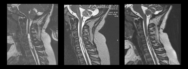
T2-weighted magnetic resonance imaging scans illustrating the cerebellar tonsillar herniation and cervical syringomyelia: from left to right, preoperative, 3-month postoperative, and 9-month postoperative views. At 3 months, following surgery, tonsillar herniation is no longer apparent, and the cervical syrinx shows continual improvement from 3 to 9 months.
When indicated, a foramen magnum expansion can be included in the osteotomy. At 3 months following the procedure, radiological changes illustrating increase in the posterior fossa volume and resolution of the cerebella tonsillar herniation can be seen. Furthermore, some reduction in the cervical syrinx is seen that continues to regress at the 9-month scan.
Posteroinferior Expansion for Turribrachycephaly
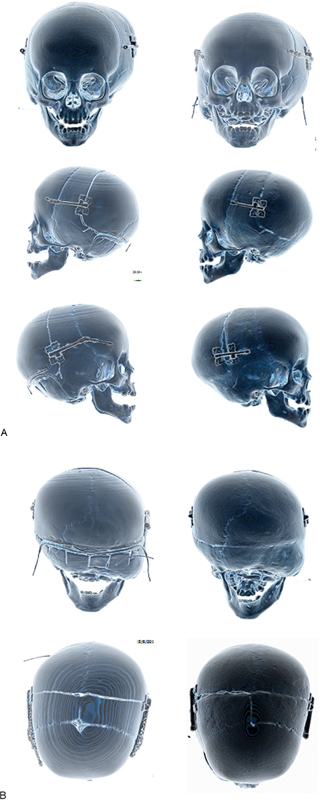
In this patient diagnosed at birth with Apert syndrome, a raised opening pressure was found on lumbar puncture, although the patient was otherwise noted to be developing well with no evidence of clinical symptoms. Imaging confirmed multisuture craniosynostosis; he underwent posterior cranial vault distraction with a posteroinferior vector to treat both cephalocranial disproportion and turribrachycephaly (Fig. 10). A 17-mm distraction was performed and the devices removed after a 2-month consolidation period.
Fig. 10.
Posterior vault expansion with a posterior inferior vector to reduce turribrachycephaly. This is an early case and illustrates the use of 4 distractors, rather than two devices as used currently.
After a relatively uncomplicated early postoperative course, it was noted at the 3-month follow-up that premature fusion of the sagittal and lambdoid sutures had occurred. The patient subsequently started to develop clinical features of raised ICP within a year following distraction of the posterior vault. Measurement of ICPs revealed mean pressures of 20 to 25 mm Hg. A further posterior vault distraction procedure was performed in a primarily posterior vector to 22-mm distraction. This postoperative course was complicated by some overgranulation at the site of one of the distracters. Following 2 months consolidation, the distracters were removed.
Three years following the second posterior cranial vault distraction, the patient continues to thrive developmentally with no symptoms of raised ICP.
Slit Ventricle Syndrome
The patient was a twin born at 26 weeks with bilateral grade 2 intraventricular hemorrhages and secondary hydrocephalus. After the first shunt surgery at the age of 3 months, over 20 subsequent shun revisions have been performed. The patient developed secondary craniosynostosis and microcephaly that was treated with cranial vault remodeling at age 4.
At the age of 15, she underwent posterior cranial vault distraction by lateral expansion of 18 mm on each side for slit ventricle syndrome (Figs. 11 and 12). Following distraction, measurement of the ICP showed pressures to be in the normal range and shunt settings were adjusted to allow the ventricles to dilate. At 3 years following distraction, no further symptoms of raised pressure or cephalocranial disproportion have been detected.
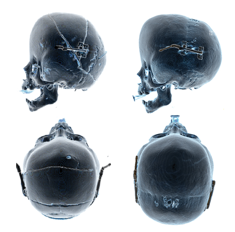
Fig. 11.
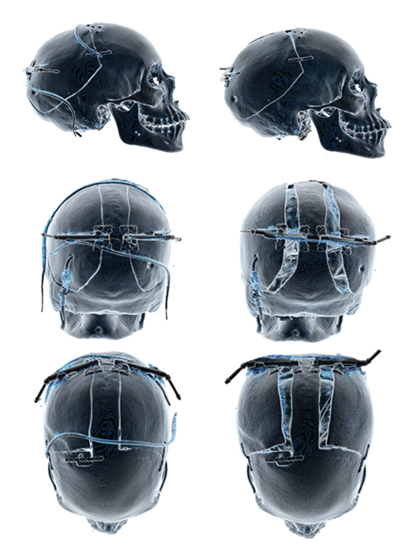
Lateral expansion of the posterior vault for treatment of shunt related slit ventricle syndrome. Note the use of the mini-plate at the anterior osteotomy to limit expansion in the desired vector. A central strut allows control to ensure symmetrical expansion. This strut should also be used in asymmetric expansion when two devices are used.
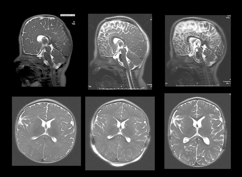
Fig. 12.

Computed tomography scans of the brain illustrating changes in the morphology of the brain with lateral expansion of the posterior cranium. In addition, increased ventricular volume is shown. From left to right, preoperative, 3-month postoperative, and 9-month postoperative views.
Intracranial Asymmetric Expansion
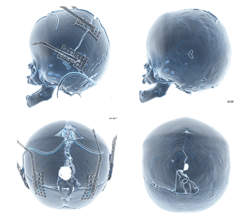
An 8-month-old girl with a nonsyndromic lambdoid craniosynostosis was treated at the age of 13 months with asymmetric posterior cranial vault distraction using two distractors (Figs. 13a and 13b). The left side was distracted by 6 mm and the right side distracted to 30 mm. At 3 years following distraction, although there was some persistent cranial asymmetry following the distraction, there were no other complications. Some improvement in cranial symmetry has been noted when viewed from above and there is no evidence of any facial asymmetry.
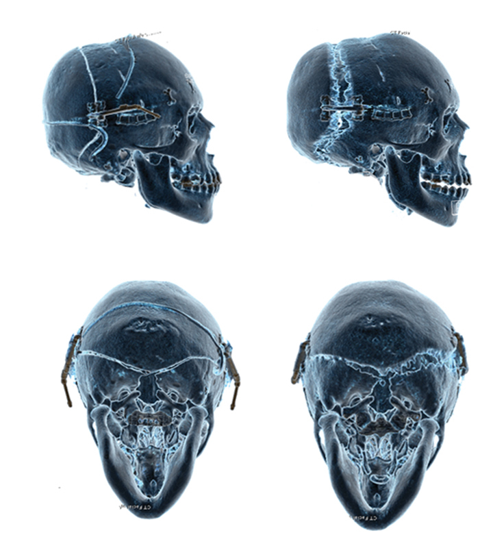
Fig. 13.
(A) Asymmetric expansion being used to partially correct the asymmetry associated with lambdoid craniosynostosis. Anterior and lateral views. (B) Asymmetric expansion used to treat lambdoid craniosynostosis. Note that although the view from the top shows good correction of the asymmetry, the mastoid bossing is not corrected. Barrel staves are also utilized to reduce the step off at the osteotomy. Posterior and top-down views.
Discussion
Children with syndromic craniosynostosis often present with numerous clinical challenges early on in life as a result of the craniofacial bony anomalies that demand correction to treat airway compromise, globe exposure, and cephalocranial disproportion. The variation in these presentations requires an individualized approach to each patient regarding their surgical strategy.
Distraction osteogenesis may offer significant advantages over tradition vault remodeling techniques in certain situations. The gradual expansion of the vault occurs over weeks. The amount of cranial vault adjustment can be tailored according to shape or ICP (with pressure monitoring) during the postoperative period. It is also a less-invasive procedure than traditional total calvarial remodeling. Furthermore, it obviates the need for bone grafting, particularly in older children and where cranial vault expansion is greater than the innate ability for bone formation to occur within the gaps. Although it requires a second procedure to remove the devices at the end of the consolidation phase, the gradual change in skull shape allows stretching of the underlying dura and venous sinuses with a reduced risk of complications such as bleeding and CSF leaks.
Dural Mobilization
Injury to the dura and CSF leakage was seen in two out of 17 cases in our series. This is comparable to other published studies. Nevertheless, we employ several specific maneuvers to reduce this risk. First, care is taken on the initial breach of the bone using a matchstick burr. Further bone cuts are made with the craniotome and the dura is carefully dissected off the bone on the anterior segments. This separation reduces the chance of injury to the dura when placing screws. It also distributes the force of distraction over a larger area of dura.
Evolution of Distractor Design
Initial attempts at cranial vault distraction were performed using devices designed for maxillary and mandibular distraction. Collaboration was conducted in concert with the manufacturer (KLS Martin, Tuttlingen, Germany), to develop a device specifically for cranial vault distraction.
Initial prototypes had a single positioning flat hook on each plate that aided orientation of the footplate to the osteotomy (Figs. 14 and 15). Each footplate was also able to rotate 20 degrees relative to the vector of distraction. In addition, the distal foot plate had a hinge that permitted a 180-degree rotation.
Fig. 14.
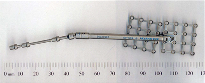
Maxillary distractor.
Fig. 15.
First prototype of custom cranial distractor illustrating hook plates. Lateral view.
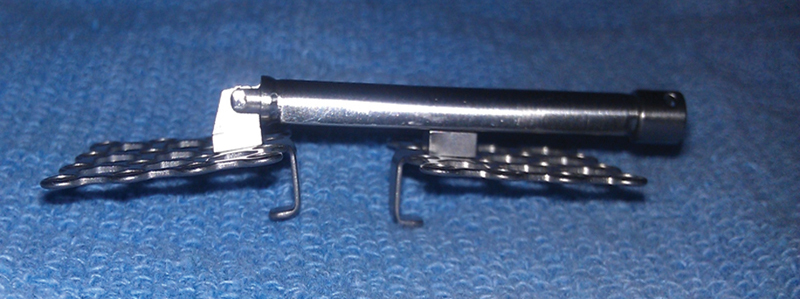
A significant problem encountered with this design was that at the conclusion of distraction the footplate was difficult to remove from the osteotomy due to the positioning hook being firmly attached within the new bone. Subsequent distractors were modified by altering the shape of the positioning hook and having two positioning hooks on each plate (Fig. 16).
Fig. 16.
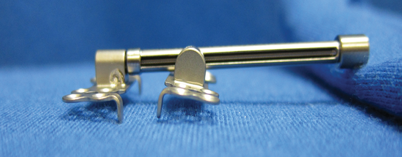
Current model illustrating single 90-degree positioning hook and smaller footplates. Lateral view.
The footplates were designed wider and shorter, with a positioning hook on either end of each footplate. The footplates were also made smaller. The distraction arm was made lower profile to ease placement under the scalp into the wound.
Furthermore, it was noted that despite maintaining a regular protocol of turning, in some cases, distraction was not achieved. The distractor devices were not found to be faulty; it was assumed that tissue contraction had reversed the gains achieved by distraction. In subsequent designs, a ratchet was incorporated into the distractor arm that prevented the recurrence of this problem.
Evolution of Distractor Usage
Initially, four distractors were placed into each patient; this was initially thought to be able to control the movement of the osteotomized segment. Difficulty was noted in distraction, in particular with the accurate orientation of the vectors of all distractors to ensure they were working in the same direction.
In subsequent cases, three distractors were trialed; eventually two distractors were found to provide the optimum balance between ease of use, stability, and ability to execute a planned distraction vector.
In our experience, the distractors failed in two patients. In one patient, the screw fixation failed and a single footplate separated from the underlying bone. This may have been due to a technical problem with placement of the fixation screws. In another patient, an intrinsic failure of the device was found to have occurred in the worm gear of the device. Again, no other complications were noted; a possible contributor to these complications was the age of the patients. This patient was age 6 at the time of distraction and sturdier distractors have been designed for use in older patients and in adults where the forces required are greater.
Variations
Distraction Vector
In other patients without a significant turricephaly, a simple posterior vector can be effective in increasing intracranial volume and improving head shape. More complex vectors can also be used where asymmetry predominates. Patients with multisutural craniosynostosis present with a range of skull morphologies and distraction osteogenesis allows for expansion along a predetermined vector. In Apert syndrome, a posterior inferior vector can be used to ameliorate the classic brachyturricephalic presentation.
Cranial Bone Deficiency
There are some circumstances in which there is a significant modification of the technique is required. Some patients with extremely thin bone or with extensive perforations secondary to thinning as result of raised ICP may not be suitable for distraction (Fig. 17). In these cases, a staged approach is used. In the first instance, a pressure-releasing procedure is performed, such as craniotomy and a modified vault remodeling allows the normalization of ICP and permits the formation of cranial bone. Following this, when bone stock is no longer a problem, either a formal vault remodeling or a distraction technique can be used to reconfigure the cranial shape.
Fig. 17.
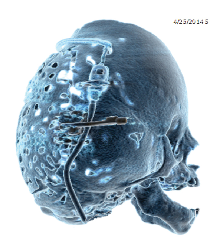
Figure illustrating the use of posterior vault distraction as the primary procedure to increase vault volume in a patient with multisuture craniosynostosis associated with Pfeiffer syndrome. Although this patient has severely deficient bone stock, the osteotomy combined with careful placement of the footplates can enable a successful expansion in these patients.
Conclusion and Future Directions
Posterior cranial vault distraction osteogenesis is an effective treatment for a variety of dysmorphologies, including single-suture, syndromic, multisuture, and acquired deformities. Asymmetric distraction can be used to correct the underlying deformity by careful planning of the distraction vector. In addition, the degree of control of the expansion process is unique to this technique, and in conjunction with ICP monitoring, can be used to tailor expansion to treat cephalocranial disproportion.
Distraction permits the regulated expansion of intracranial volume to address raised ICP within the design limits of the device employed.
Here we have presented the surgical and technological refinements of using cranial-specific distractors in our institution, which has allowed for successful distraction for several conditions while minimizing complications.
Although the indications for distraction osteogenesis in the calvarium are being increasingly recognized, this technique warrants further investigation. Potential future lines of study include defining the cellular events that lead to the regeneration of new bone during the process of distraction and the mechanical and biological factors that lead to optimal healing.
In addition, further clinical work is required to define the distraction protocols such as latency, rate of distraction, and consolidation times in the individual clinical conditions in which this technique is utilized.
References
- 1.Renier D, Sainte-Rose C, Marchac D, Hirsch J F. Intracranial pressure in craniostenosis. J Neurosurg. 1982;57(3):370–377. doi: 10.3171/jns.1982.57.3.0370. [DOI] [PubMed] [Google Scholar]
- 2.McCarthy J G Schreiber J Karp N Thorne C H Grayson B H Lengthening the human mandible by gradual distraction Plast Reconstr Surg 19928911–8., discussion 9–10 [PubMed] [Google Scholar]
- 3.Yonehara Y, Hirabayashi S, Sugawara Y, Sakurai A, Harii K. Complications associated with gradual cranial vault distraction osteogenesis for the treatment of craniofacial synostosis. J Craniofac Surg. 2003;14(4):526–528. doi: 10.1097/00001665-200307000-00025. [DOI] [PubMed] [Google Scholar]
- 4.Yano H Tanaka K Sueyoshi O Takahashi K Hirata R Hirano A Cranial vault distraction: its illusionary effect and limitation Plast Reconstr Surg 20061171193–200., discussion 201 [DOI] [PubMed] [Google Scholar]
- 5.Esparza J, Hinojosa J, García-Recuero I, Romance A, Pascual B, Martínez de Aragón A. Surgical treatment of isolated and syndromic craniosynostosis. Results and complications in 283 consecutive cases. Neurocirugia (Astur) 2008;19(6):509–529. doi: 10.1016/s1130-1473(08)70201-x. [DOI] [PubMed] [Google Scholar]
- 6.Esparza J, Hinojosa J. Complications in the surgical treatment of craniosynostosis and craniofacial syndromes: apropos of 306 transcranial procedures. Childs Nerv Syst. 2008;24(12):1421–1430. doi: 10.1007/s00381-008-0691-8. [DOI] [PubMed] [Google Scholar]
- 7.Cho B C, Hwang S K, Uhm K I. Distraction osteogenesis of the cranial vault for the treatment of craniofacial synostosis. J Craniofac Surg. 2004;15(1):135–144. doi: 10.1097/00001665-200401000-00034. [DOI] [PubMed] [Google Scholar]
- 8.White N, Evans M, Dover M S, Noons P, Solanki G, Nishikawa H. Posterior calvarial vault expansion using distraction osteogenesis. Childs Nerv Syst. 2009;25(2):231–236. doi: 10.1007/s00381-008-0758-6. [DOI] [PubMed] [Google Scholar]
- 9.Choi M, Flores R L, Havlik R J. Volumetric analysis of anterior versus posterior cranial vault expansion in patients with syndromic craniosynostosis. J Craniofac Surg. 2012;23(2):455–458. doi: 10.1097/SCS.0b013e318240ff49. [DOI] [PubMed] [Google Scholar]
- 10.Goldstein J A, Paliga J T, Wink J D, Low D W, Bartlett S P, Taylor J A. A craniometric analysis of posterior cranial vault distraction osteogenesis. Plast Reconstr Surg. 2013;131(6):1367–1375. doi: 10.1097/PRS.0b013e31828bd541. [DOI] [PubMed] [Google Scholar]
- 11.Heller J B, Lazareff J, Gabbay J S, Lam S, Kawamoto H K, Bradley J P. Posterior cranial fossa box expansion leads to resolution of symptomatic cerebellar ptosis following Chiari I malformation repair. J Craniofac Surg. 2007;18(2):274–280. doi: 10.1097/scs.0b013e31802c05ab. [DOI] [PubMed] [Google Scholar]
- 12.Steinbacher D M, Skirpan J, Puchała J, Bartlett S P. Expansion of the posterior cranial vault using distraction osteogenesis. Plast Reconstr Surg. 2011;127(2):792–801. doi: 10.1097/PRS.0b013e318200ab83. [DOI] [PubMed] [Google Scholar]
- 13.Taylor J A, Derderian C A, Bartlett S P, Fiadjoe J E, Sussman E M, Stricker P A. Perioperative morbidity in posterior cranial vault expansion: distraction osteogenesis versus conventional osteotomy. Plast Reconstr Surg. 2012;129(4):674e–680e. doi: 10.1097/PRS.0b013e3182443164. [DOI] [PubMed] [Google Scholar]
- 14.Wiberg A, Magdum S, Richards P G, Jayamohan J, Wall S A, Johnson D. Posterior calvarial distraction in craniosynostosis - an evolving technique. J Craniomaxillofac Surg. 2012;40(8):799–806. doi: 10.1016/j.jcms.2012.02.018. [DOI] [PubMed] [Google Scholar]