Abstract
We propose a method to control electromagnetic (EM) radiations by holographic metasurfaces, including to producing multi-beam scanning in one dimension (1D) and two dimensions (2D) with the change of frequency. The metasurfaces are composed of subwavelength metallic patches on grounded dielectric substrate. We present a combined theory of holography and leaky wave to realize the multi-beam radiations by exciting the surface interference patterns, which are generated by interference between the excitation source and required radiation waves. As the frequency changes, we show that the main lobes of EM radiation beams could accomplish 1D or 2D scans regularly by using the proposed holographic metasurfaces shaped with different interference patterns. This is the first time to realize 2D scans of antennas by changing the frequency. Full-wave simulations and experimental results validate the proposed theory and confirm the corresponding physical phenomena.
In recent years, it has been shown that extreme controls of electromagnetic (EM) waves can be achieved by using metasurfaces. Due to advantages of smaller physical space and less lossy structures than bulk metamaterial1,2,3,4,5,6, metasurfaces have found great potential applications in both microwave and optical frequencies. Similar to metamaterials, the metasurfaces are also modeled as sub-wavelength textures and several analysis methods have been established. Typically, the surface impedance or effective surface refractive index can be calculated analytically using the transverse resonance approach7, from which surface-wave waveguides8 and lenses9,10,11 have been designed. To reduce the computational time in eigen-mode simulations, a fast method was presented to calculate the surface impedance efficiently12. Later, the printed-circuit tensor impedance surface13 has been analyzed using the modified transverse resonance technique and idealized tensor impedance boundary condition. Another method to model metasurface or metafilm is the generalized sheet transition condition14, in which the small scatterers are characterized as electric and magnetic polarization densities. Based on this method, reflection and transmission coefficients of metafilms or metasurfaces have been obtained15,16, promoting the study of meta-transmission arrays17,18,19. To control EM waves with more flexibility, the generalized Snell's law was proposed20 by introducing the abrupt phases on the interface of the two media. Based on similar ideas, a gradient-index metasurface was presented to convert propagating waves to surface waves efficiently21 and convert the circularly-polarized light to cross-polarized light22,23.
On the other hand, due to the low profile and low loss, metasurfaces have great advantages in the design of surface aperture antennas. Based on the original analysis of sinusoidally-modulated reactance surface24, the holographic antenna composed of surface impedance was proposed25, which shapes the monopole source as a pencil beam in the far-field region and changes the linearly-polarized source to circularly-polarized radiation by using anisotropic surface impedance units. Later, a spiral leaky-wave antenna26 based on the modulated isotropic surface impedance implemented by corrugated dielectric or metallic patches on a grounded substrate can generate circularly polarized waves. Then the anisotropic tensor surface impedance formed by isotropic textures was used to realize circularly-polarized isoflux radiations27 for space-to-ground data link applications in the X-band. In study of microwave imaging, a concept of metamaterial aperture has been presented for computational imaging28,29, in which the random-aperture leaky-wave antennas composed of complementary electric-inductor-capacitor elements have been used to generate multi- beam radiation patterns. The metasurface antennas can also be tunable30,31 and conformal32,33 so that they are more functional and practical in many engineering applications.
In this work, we propose to control extreme EM radiations by using holographic metasurfaces, which can radiate multiple beams with the frequency sweeping in one dimension (1D) or two dimensions (2D) without using the complicated beam-forming network34 and anisotropic structures35,36. The proposed metasurfaces are composed of sub-wavelength quasi-periodic metallic patches on a grounded dielectric substrate, which can be shaped by mapping the variation of patch gaps to the surface impedance under the particular holographic interference. Once the interference pattern is recorded by the interference between reference waves and multi-beam radiations on the metasurface aperture, according to microwave holography theory, the metasurface excited by the reference waves generated by a monopole antenna can reproduce the multiple beams as we desire. We demonstrate that the radiation waves generated by the holographic metasurface can accomplish 2D scans regularly with the change of frequency, which has not been realized in the earlier holographic metasurfaces and leaky-wave antennas.
Results
Theory and analysis
The surface impedance is defined as the ratio of electric to magnetic fields near a surface. Hence, the perfectly electric conducting (PEC) and perfectly magnetic conducting (PMC) surfaces are physically zero-impedance and high-impedance surfaces, respectively. We can design a metasurface by forming quasi-periodic gradient distribution of surface impedance. According to microwave holography theory, the desired radiation beam can be produced by using a reference wave to excite holographic interferogram, which is generated by the interference between the reference wave and radiation wave. The interferogram equation is given as37
 |
in which Ψref is the reference wave and Ψobj is the object wave. To design the surface-aperture radiations, we use the distribution of surface impedance to embody the whole surface interferogram. We rewrite Eq. (1) to describe the distribution of surface impedance as
 |
where X and M indicate the average value of surface impedance and the modulation depth, respectively, and “*” represents the conjugate operation. To build up the object wave (or radiation wave), we should use the reference wave to excite the interference pattern in determining  .
.
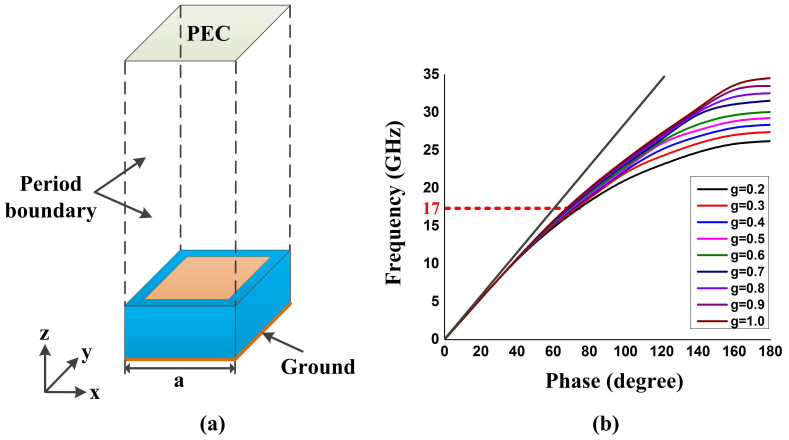
In our design, the basic unit of metasurface is a sub-wavelength metallic patch on a grounded substrate, as shown in Fig. 1(a). We extract the surface impedance of the metasurface via its dispersion curve. When the surface-wave vector ktpasses through a unit cell, the phase difference across the unit is ϕ = kta, which can be acquired under eigen-mode simulations, where a is the period of the unit cell. Then the surface refractive index is given as n = c/vt = ktc/ωt, where c is the light speed in free space and ωt is the surface angular frequency. Combining with the equation of surface impedance Z = jZ0kz/k of the transverse-magnetic (TM) modes, we obtain the relation between the unit phase difference and surface impedance as
 |
where Z0 is the impedance in free space. Therefore, once the unit phase difference is acquired through the eigen-mode simulation, we can calculate the surface impedance. The gap between square patches (see the orange area in Fig. 1(a)) determines the value of surface impedance. When slowly varying the gap sizes to obtain different surface impedances, the structure is considered as quasi-periodic.
Figure 1.
(a) Structure of the metallic patch on a grounded dielectric substrate, in which the blue and orange areas are dielectric and metal. The period of square lattice is a = 3 mm, and the gap size varies from 0.2 to 1.0 mm. F4B is chosen as the dielectric substrate with the relative permittivity 2.2 and the thickness 1.57 mm. (b) The dispersion curves of unit cells with different gap sizes. The black oblique line is the light line.
From the nine dispersion curves with changing gap sizes shown in Fig. 1(b), we calculate nine values of surface impedance at 17 GHz, from which the following equation is fitted using cubic polynomials to describe the relationship between surface impedance and gap size:
 |
Then we determine the values of X and M as 197.5 and 36.5, respectively, from the simulated values of surface impedance.
According to the holographic antenna theory, once the interference pattern is recorded by the interaction between reference wave and multi-beam radiation wave on the metasurface, we can reconstruct the multiple beams as we desire. We choose a monopole antenna placed in the center of metasurface to produce the reference wave, which is written as
 |
where n is the effective surface refractive index and r is the distance from the origin to the surface radiation unit. For double-beam radiation, the object wave (i.e. the desired radiation wave) can be defined as
 |
in which  and
and  are wave-number vectors of the two beams with the elevation and azimuth angles θ1/2 and ϕ1/2, respectively, and
  is the spatial location vector. In particular, when θ1 = θ2 = 30° and φ1 = 45°, φ2 = 135°, Eq. (6) is rewritten as
 |
in which the positive and negative exponential terms indicate the radiation waves propagating to the two sides of the normal direction on the metasurface. To obtain the double-beam radiation shaped by Eq. (7), the interferogram generated by Eq. (2) should be excited by the reference wave defined in Eq. (5).
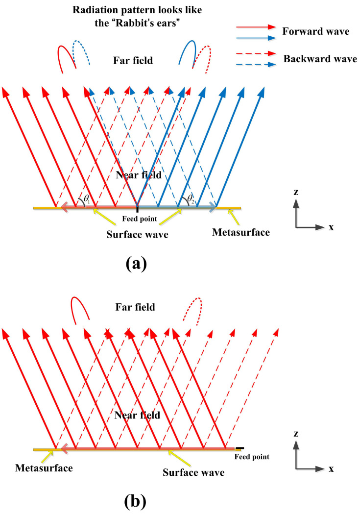
We will show later that the proposed holographic metasurface is equivalent to the 2D leaky-wave structure. To radiate EM waves more efficiently, we define the “-1” order leaky-wave radiation without other Floquet modes participating the interference by synthetically considering the unit design and radiation frequency. In fact, the forward and backward waves in leaky waves mean that the radiation directions are uniform and non-uniform with the propagation of surface waves. If we place the monopole antenna in the center of metasurface as excitation, the full-wave simulation results reveal that the leaky-wave (object-wave) radiation pattern may generate the sag like “rabbit's ears” in the far fields, as shown in Fig. 2(a). This phenomenon is caused by the slightly radiating deviation of forward and backward modes, which is attributed to the inaccuracy of effective surface refractive index that determines the distribution of surface currents. The surface currents excited by the monopole antenna will not be completely the same as the reference wave so that the forward and backward waves have different radiation directions, as illustrated in Fig. 2(a).
Figure 2.
(a) The double-beam “rabbit's ear” phenomenon, which is caused by the central feeding on the metasurface. (b) The side-feeding method to avoid the “rabbit's ear” phenomenon.
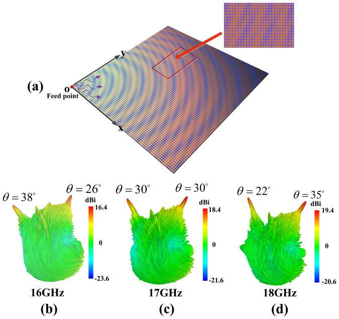
The optimization of surface refractive index n can avoid the “rabbit's ear” phenomenon by enforcing θ1 = θ2 in Fig. 2(a), but it is more complicated. Here, we present a side-feeding method, as shown in Fig. 2(b). The interferogram shaped by the holographic metasurface is generated by Eq. (2), which is combined with Eq. (4) to determine the relation to describe the gap size versus position on the metasurface. Fig. 3(a) illustrates the interferogram generated by the interference between double-beam radiation (Eq. (7)) and reference (Eq. (5)) waves at 17 GHz. Based on the full-wave simulations by commercial software, CST Microwave Studio, the reproduced waves are demonstrated in Fig. 3(c). We also show that the double-beam radiations can make 1D scan with the change of frequency (16–18 GHz), as clearly observed in Figs. 3(b) – (d).
Figure 3.
(a) The holographic metasurface that can generate double-beam radiations from the side feeding. (b–d) The full-wave simulation results of 1D scanning of double beams at 16, 17 and 18 GHz, respectively.
To explain the phenomenon of frequency scanning by the 2D metasurface, we now show the equivalence of the holographic reproduction and “-1”-order leaky-wave radiation. For simplicity, we analyze a single-beam radiation defined by Ψobj = e−jkxsin(θ), which will interference with reference wave Ψref = e−jknx to generate the interferogram as
 |
To obtain periodicity of the holographic distribution of surface impedance along the x direction, we define k0nx-k0x sin(θ) = 2π, and the corresponding period is determined as
 |
which can be rewritten as
 |
The above result is exactly the same as that in the “-1”-order leaky-wave radiation12. Here, θ is the radiation direction of the holographic reproduction. It is obvious that the object wave can accomplish the beam scanning controlled by frequency, and the corresponding radiation direction is given as
 |
where k′, n′ and θ′ are the same as those in Eq. (8) but under different operating frequencies.
We introduce the concept of surface-wave phase gradient to explain the above phenomenon. For simplicity, we still analyze the single-beam radiation defined by  and
and  , which generate the interferogram as
 |
Here, we assume that the sinusoidal phase distribution ( ) of interferogram generated by the impedance units is approximately invariant by changing frequencies since the higher- and lower-impedance areas of the interferogram are fixed. Hence we only need to concern the object wave term in processing the holographic reproduction. If we excite the interferogram by reference wave defined as
  , where k′ and n′are the wave number in free space and effective refractive index, then the phase of surface-wave front
  becomes Φ = k′n′r−k0nr + sin(θ)k0[x cos(φ) + y sin(φ)]. By calculations, the surface-wave phase gradient ∇Φ is given as
 |
where  ,
,  and
and  are unit vectors. Hence the surface wave front is generated by the interference of two surface waves
  and
and  , and the phase of wave front in the x direction is written as
 |
where φ is the angle between r and x directions. Thus, the x component of effective surface wave number at the particular frequency is
 |
which is corresponding to the wave number of the “-1” order leaky-wave. Likewise, the y component of effective surface wave number at the particular frequency is
 |
Thus, the amplitude and azimuth angle of the effective surface wave number are given as
 |
 |
As a consequence, the elevation angle of the main radiation direction is expressed as
 |
According to Eq. (18), if we change the object wave as  (φ = 45°; the interferogram is defined in the area of x>0 and y>0), in which “+” and “−” represent the backward and forward modes of leaky waves, we find that the azimuth angle of main radiation direction will be unchanged with frequencies under the circumstance of
  , which can accomplish 1D scanning controlled by frequency, as shown in the simulation results in Fig. 3.
This method can be generalized to produce multi-beam radiations by recording interferograms in several subareas, each of which radiates a single beam. For instance, in four-beam radiations, the overall interferogram is generated by mirroring the metasurface pattern in the first quadrant to other quadrants. The object wave is then given as
 |
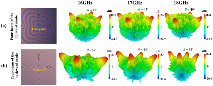
in which we determine φ = 45° to satisfy the condition of  , and the azimuth angles of the desired four beams are 45°, 135°, 225°, and 315°, respectively. When we set θ = 45°, the corresponding interferograms and simulation results for forward and backward modes are presented in Figs. 4(a) and (b). Although the feeding point is located in the center of the overall metasurface, for each radiation beam, it is the side feeding in the subarea. Hence the earlier “rabbit's ears” phenomena are avoided. From Fig. 4, we notice that the four-beam radiations in the backward mode are scanned in 1D direction with increasing elevation angles as the frequency becomes larger; while the four beams in the forward mode are scanned with decreasing elevation angles.
Figure 4.
(a) The four-beam radiations of the forward mode with the frequency scanning, in which the elevation angle becomes large as the frequency increases. (b) The four-beam radiations of the backward mode with the frequency scanning, in which the elevation angle becomes small as the frequency increases. The azimuth angles of the four radiation beams are 45°, 135°, 225°, and 315°, respectively, in both cases.
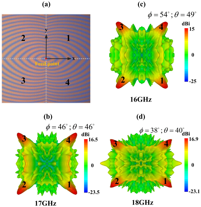
From Eq. (18) and (19), if  , we can realize extreme controls of the multi-beam radiations, in which the azimuth angle (ϕ′) and elevation angle (θ′) of the leaky waves can be simultaneously scanned with the change of frequency. In this case, the object wave with four-beam radiations is defined as
 |
in which we determine φ = 135°and θ = 45° to satisfied the condition  . The corresponding interferogram and simulation results of the four-beam radiations with 2D frequency scanning are demonstrated in Fig. 5. We clearly observe that the four-beam radiation patterns are scanned in both azimuth and elevation directions as the operating frequency changes. The detailed scanning properties are summarized in Table 1, from which we notice that the simulation results have good agreements to the theoretical analysis. The little deviation may be caused by the inaccuracy of effective surface refractive index and approximate condition of sinusoidal phase distribution under different frequencies. Compared to the conventional holographic leaky-wave radiations that can only accomplish 1D frequency scanning, the proposed method and holographic metasurface have greatly enhanced the capabilities to reach 2D frequency scanning.
Figure 5. The simulation results of the four-beam 2D frequency scanning, in which the radiation patterns are scanned in both azimuth and elevation directions with the change of operating frequencies.
Table 1. Detailed scanning properties for one of the four-beam radiations.
| Frequency | 16 GHz | 17 GHz | 18 GHz | |||
|---|---|---|---|---|---|---|
| Azimuth and Elevation | ϕ | θ | ϕ | θ | ϕ | θ |
| Theoretical Analysis | 53° | 50° | 45° | 45° | 37° | 42° |
| Simulation Result | 54° | 49° | 46° | 46° | 38° | 40° |
Fabrication and Measurement
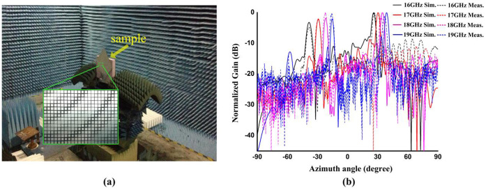
To validate the proposed method experimentally, we fabricate a sample of the holographic leaky-wave metasurface shown in Fig. 3 to show the frequency scanning properties of two beams. The sample of the double-beam metasurface has a dimension of 240 × 240 mm2, containing 6400 unit cells. In fabrication, we choose commercial printed circuit board (FR4) as the dielectric substrate and choose copper with tinning as the ground. The experimental setup in anechoic chamber to measure the far fields is illustrated in Fig. 6(a), and the measured far-field radiation patterns with the 1D frequency scanning in azimuth direction of the double-beam holographic metasurface are demonstrated in Fig. 6(b).
Figure 6.
(a) The fabricated sample of the double-beam holographic metasurface and experimental setup. (b) The measured far-field radiation patterns of the holographic metasurface and their comparisons to simulation results.
The detailed double-beam scanning parameters of the holographic metasurface from theoretical analysis, simulation and experimental results are presented in Table 2. We clearly observe that the experimental results have good agreements to numerical simulation and theoretical predictions. We do not measure the four-beam radiations with 2D frequency scanning due to the much complicated experimental process based on our current measurement system, but the simulation results in Fig. 5 and Table 1 have verified the good performance to make extreme controls of EM radiations only by frequency.
Table 2. The detailed parameters of double-beam scanning in theoretical analysis.
| Frequency | 16 GHz | 17 GHz | 18 GHz | 19 GHz | ||||
|---|---|---|---|---|---|---|---|---|
| Elevation and azimuth | θ1 ϕ = 0° | θ2 ϕ = 180° | θ1 ϕ = 0° | θ2 ϕ = 180° | θ1 ϕ = 0° | θ2 ϕ = 180° | θ1 ϕ = 0° | θ2 ϕ = 180° |
| Theoretical analysis | 24° | 38° | 30° | 30° | 34° | 22° | 40° | 14° |
| Simulation results | 26° | 38° | 30° | 29° | 35° | 22 | 39° | 15° |
| Experimental results | 25° | 38° | 30° | 29° | 37° | 22 | 41° | 14° |
Discussion
We proposed an efficient method to design holographic leaky-wave metasurfaces to perform complicated multi-beam radiations with frequency scanning. We presented two approaches to record the desired interferograms, one of which is recorded on the whole metasurface with side feeding, and the other of which is recorded on several subdomains of the metasurface with central feeding. According to theoretical analysis, the first approach can accomplish 1D frequency scanning, while the second can reach 1D and/or 2D frequency scanning. Numerical simulation and experiment results show that the radiation beam directions in the far fields can be coded by frequency instead of complicated feeding network. The proposed method has potential applications in the satellite communications and radar systems, and can be extended to the millimeter wave and THz regimes.
Author Contributions
Y.B.L. and T.J.C. conceived the idea, did the theoretical calculations, and wrote the manuscript. Y.B. Li designed the samples and performed the measurements. X.W., B.G.C. and Q.C. involved in the simulations and measurement. All authors contributed to the discussions.
Acknowledgments
This work was supported by the National Science Foundation of China (60990320, 61138001,61171026 and 60990324), National High Tech (863) Projects (2011AA010202 and 2012AA030402), 111 Project (111-2-05) and the Natural Science Foundation of the Jiangsu Province BK2012019, and 20130202 Guangxi Experiment Center of Information Science, Guilin University of Electronic Technology.
References
- Smith D. R., Pendry J. B. & Wiltshire M. C. K. Metamaterials and Negative Refractive Index. Science 305, 788 (2004). [DOI] [PubMed] [Google Scholar]
- Schurig D. et al. Metamaterial Electromagnetic Cloak at Microwave Frequencies. Science 314, 977 (2006). [DOI] [PubMed] [Google Scholar]
- Luo Y., Zhang J. J., Wu B. I. & Chen H. S. Interaction of an electromagnetic wave with a cone-shaped invisibility cloak and polarization rotator. Phys. Rev. B 78, 125108 (2008). [Google Scholar]
- Liu R. et al. Broadband Ground-Plane Cloak. Science 323, 366 (2009). [DOI] [PubMed] [Google Scholar]
- Lai Y., Chen H. Y., Zhang Z. Q. & Chan C. T. Complementary Media Invisibility Cloak that Cloaks Objects at a Distance Outside the Cloaking Shell. Phys. Rev. Lett. 102, 093901 (2009). [DOI] [PubMed] [Google Scholar]
- Zhou J. F. et al. Terahertz chiral metamaterials with giant and dynamically tunable optical activity. Phys. Rev. B 86, 035448 (2012). [Google Scholar]
- Collin R. E. Field Theory of Guided Waves (McGraw-Hill, New York, 1960). [Google Scholar]
- Gregoire D. J. & Kabakian A. V. Surface-wave waveguides. IEEE Antennas Wireless Propag. Lett. 10, 1512 (2011). [Google Scholar]
- Bosiljevac M., Casaletti M., Caminita F., Sipus Z. & Maci S. Non-Uniform Metasurface Luneburg Lens Antenna Design. IEEE Trans. Antennas Propag. 60, 4065 (2012). [Google Scholar]
- Dockrey J. A. et al. Thin metamaterial Luneburg lens for surface waves. Phys. Rev. B 87, 125137 (2013). [Google Scholar]
- Wan X., Jiang W. X., Ma H. F. & Cui T. J. A broadband transformation-optics metasurface lens. Opt. Express 21, 17531(2013).23938624 [Google Scholar]
- Patel A. M. & Grbic A. A printed leaky-wave antenna based on a sinusoidally-modulated reactance surface. IEEE Trans. Antennas Propag. 59, 2087 (2011). [Google Scholar]
- Patel A. M. & Grbic A. Effective Surface Impedance of a Printed-Circuit Tensor Impedance Surface (PCTIS). IEEE Trans. Antennas Propag. 61, 1403 (2013). [Google Scholar]
- Kuester E. F., Mohamed M. A., Piket-May M. & Holloway C. L. Averaged transition conditions for electromagnetic fields at a metafilm. IEEE Trans. Antennas Propag. 51, 2641 (2003). [Google Scholar]
- Holloway C. L., Mohamed M. A., Kuester E. F. & Dienstfrey A. Reflection and transmission properties of a metafilm: With an application to a controllable surface composed of resonant particles. IEEE Trans. Antennas Propag. 47, 853 (2005). [Google Scholar]
- Holloway C. L. et al. An Overview of the Theory and Applications of Metasurfaces: The Two-Dimensional Equivalents of Metamaterials. IEEE Trans. Antennas Propag. 54, 10 (2012). [Google Scholar]
- Zhao Y., Engheta N. & Alù A. Homogenization of plasmonic metasurfaces modeled as transmission-line loads. Metamaterials 5, 90 (2011). [Google Scholar]
- Belokopytov G. V., Zhuravlev A. V. & Terekhov Y. E. Transmission of an electromagnetic wave through a bianisotropic metafilm. Phys. Wave Phenom. 19, 280 (2011). [Google Scholar]
- Pfeiffer C. & Grbic A. Metamaterial Huygens' Surfaces: Tailoring Wave Fronts with Reflectionless Sheets. Phys. Rev. Lett. 110, 197401 (2013). [DOI] [PubMed] [Google Scholar]
- Yu N. et al. Light Propagation with Phase Discontinuities: Generalized Laws of Reflection and Refraction. Science 334, 333 (2011). [DOI] [PubMed] [Google Scholar]
- Sun S. et al. Gradient-index meta-surfaces as a bridge linking propagating waves and surface waves. Nat. Mater. 11, 426 (2012). [DOI] [PubMed] [Google Scholar]
- Kang M., Feng T. H., Wang H. T. & Li J. Wave front engineering from an array of thin aperture antennas. Opt. Express 20, 15882 (2012). [DOI] [PubMed] [Google Scholar]
- Chen X. Z. et al. Dual-polarity plasmonic metalens for visible light. Nat. Commun. 3, 1198 (2012). [DOI] [PMC free article] [PubMed] [Google Scholar]
- Oliner A. A. & Hessel A. Guided waves on sinusoidally-modulated reactance surfaces. IEEE Trans. Antennas Propag. 7, 201 (1959). [Google Scholar]
- Fong B. H., Colburn J. S., Ottusch J. J., Visher J. L. & Sievenpiper D. F. Scalar and Tensor Holographic Artificial Impedance Surfaces. IEEE Trans. Antennas Propag. 58, 3212 (2010). [Google Scholar]
- Minatti G., Caminita F., Casaletti M. & Maci S. Spiral leaky-wave antennas based on modulated surface impedance. IEEE Trans. Antennas Propag. 59, 4436 (2011). [Google Scholar]
- Minatti G., Maci S., De Vita P., Freni A. & Sabbadini M. A circularly-polarized isoflux antenna based on anisotropic metasurface. IEEE Trans. Antennas Propag. 60, 4998 (2012). [Google Scholar]
- Hunt J. et al. Metamaterial apertures for computational imaging. Science 339, 310 (2013). [DOI] [PubMed] [Google Scholar]
- Lipworth G. et al. Metamaterial apertures for coherent computational imaging on the physical layer. J.Opt.Soc.Am.A 30, 1603 (2013). [DOI] [PubMed] [Google Scholar]
- Sievenpiper D. F., Schaffner J. H., Song H. J., Loo R. Y. & Tangonan G. Two-dimensional beam steering using an electrically tunable impedance surface. IEEE Trans. Antennas Propag. 51, 2713 (2003). [Google Scholar]
- Zhao J. et al. A tunable metamaterial absorber using varactor diodes. New J. Phys. 15, 043049 (2013). [Google Scholar]
- Gregoire D. J. 3-D Conformal Metasurfaces. IEEE Antennas Wireless Propag. Lett. 12, 233 (2013). [Google Scholar]
- Germain D., Seetharamdoo D., Burokur S. N. & De Lustrac A. Phase-compensated metasurface for a conformal microwave antenna. Appl. Phys. Lett. 103, 124102 (2013). [Google Scholar]
- Chu T. S. & Hashemi H. True-Time-Delay-Based Multi-Beam Arrays. IEEE Trans. Microwave Theory Tech. 61, 3072 (2013). [Google Scholar]
- Cheng Q., Jiang W. X. & Cui T. J. Multi-beam generations at pre-designed directions based on anisotropic zero-index metamaterials. Appl. Phys. Lett. 99, 131913 (2011). [Google Scholar]
- Tichit P., Burokur S. N. & De Lustrac A. Spiral-like multi-beam emission via transformation electromagnetics. J. Appl. Phys. 115, 024901 (2014). [Google Scholar]
- Hariharan P. Optical Holography: Principles, Techniques and Applications. (Cambridge Univ. Press, Cambridge, U. K 1996). [Google Scholar]


