Abstract.
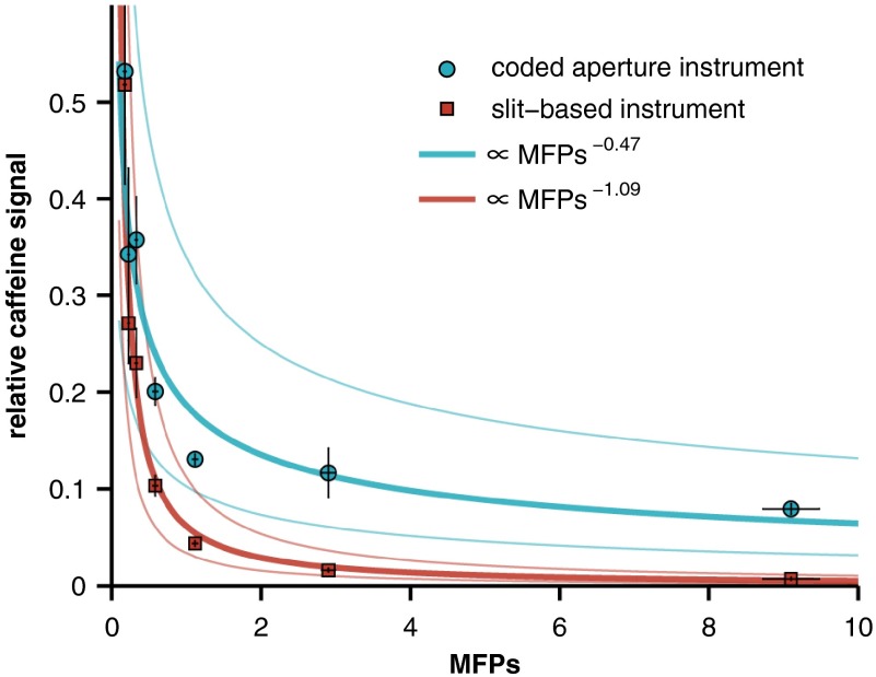
Traditional slit-based spectrometers have an inherent trade-off between spectral resolution and throughput that can limit their performance when measuring diffuse sources such as light returned from highly scattering biological tissue. Recently, multielement fiber bundles have been used to effectively measure diffuse sources, e.g., in the field of spatially offset Raman spectroscopy, by remapping the source (or some region of the source) into a slit shape for delivery to the spectrometer. Another approach is to change the nature of the instrument by using a coded entrance aperture, which can increase throughput without sacrificing spectral resolution. In this study, two spectrometers, one with a slit-based entrance aperture and the other with a coded aperture, were used to measure Raman spectra of an analyte as a function of the optical properties of an overlying scattering medium. Power-law fits reveal that the analyte signal is approximately proportional to the number of transport mean free paths of the scattering medium raised to a power of (coded aperture instrument) or (slit-based instrument). These results demonstrate that the attenuation in signal intensity is more pronounced for the slit-based instrument and highlight the scattering regimes where coded aperture instruments can provide an advantage over traditional slit-based spectrometers.
Keywords: Raman spectroscopy, coded aperture spectroscopy, biological tissue
1. Introduction
Measuring analytes in biological tissue both noninvasively and in vivo has become the focus of a growing body of research in optical spectroscopy. For example, near-infrared, vibrational Raman spectroscopy has been extensively used to diagnose and monitor disease in a variety of tissues.1–4 Historically, these measurements have been acquired with traditional, slit-based spectrometers, which have an inherent trade-off between spectral resolution and throughput (also known as étendue)—larger slits yield greater throughput, but result in decreased spectral resolution. Measuring diffuse sources, such as light returned from highly scattering biological tissue, with high spectral resolution, can therefore be challenging with slit-based instruments.
The étendue, or flux gathering capability, of a spectrometer is given by
| (1) |
where is the area of the entrance window and is the solid angle subtended by the entrance pupil as seen from the entrance window. For a slit-based spectrometer with a given optical arrangement, the étendue can only be adjusted by changing the size of the entrance slit—a larger slit will yield greater étendue, but it will also negatively impact the spectral resolution. Because Raman-scattered light returned from biological tissue is generally large in both spatial and angular extent (i.e., and ), the étendue of the returned light is often greater than that provided by high-spectral resolution, slit-based spectrometers.
One method that has been developed to measure diffuse sources involves using a bundle with multiple optical fibers to remap the spatial distribution of the source into a slit shape for delivery to the spectrometer.5,6 Although this approach has the same trade-off between spectral resolution and étendue that is inherent in slit-based instruments, it is useful when the spatial distribution of the source does not match the shape of the entrance slit. Practically, by using a multielement fiber bundle, the full height of a two-dimensional detector can be used, which can provide superior sensitivity relative to conventional slit-based detection. Multielement fiber bundles have also been widely used to measure subsurface layers by taking advantage of an offset between the illumination and collection regions on the surface of the sample.7–13 This approach, known as spatially offset Raman spectroscopy (SORS), was developed to isolate Raman signals from subsurface layers with the depth sensitivity governed by the offset between illumination and collection regions. Other techniques used to measure analytes beneath turbid media include transmission Raman spectroscopy,14 surface-enhanced SORS,15 and Kerr-gated Raman spectroscopy.16 A thorough review of these technologies was recently completed by Matousek and Stone.17 These studies have shown that multielement fiber bundles can effectively acquire Raman spectra of diffuse sources, with only minor losses introduced by the fiber packing fraction and coupling losses to the individual elements of the bundle.
Another approach that has been used to measure diffuse sources involves placing coded apertures (e.g., multiple slits) in the entrance and exit planes of the instrument.18 Unlike traditional slit-based detection, this approach can increase the étendue of the spectrometer without sacrificing spectral resolution. Modern coded aperture spectrometers that utilize multichannel detectors require only one coded aperture and are often referred to as static, multimodal, and multiplex spectrometers.19 Over the past decade, new classes of aperture codes have been studied;19,20 the approach has been extended to hyperspectral imaging;21 the signal-to-noise ratio (SNR) properties of coded aperture instruments have been examined;22 and coded apertures have been coupled with Raman spectroscopy to measure ethanol concentrations in tissue phantoms.23 Generally speaking, and as discussed in further detail below, coded aperture instruments are best suited to applications where the étendue of the source is larger than that of more traditional detection schemes and where high spatial resolution is not required.
Many applications of Raman spectroscopy involve measuring concentrations of analytes beneath highly scattering turbid media. In the subfield of biomedical Raman spectroscopy, these include transcutaneous measurements of blood glucose levels,24 breast tumor tissue,25 bone,26 and the pharmacokinetics of various topically applied drugs.27 Our laboratory is particularly interested in validating pharmacokinetic models of topically applied drugs used for prophylaxis against human immunodeficiency virus.28 Although the methods described above can increase instrument étendue, collection efficiency, and/or sensitivity to these targeted analytes, the obtained signal is still attenuated by the presence of the overlying layer. However, the rate of attenuation may be modified by the collection and detection method. In this study, we seek to characterize how the measured Raman signal from an analyte is attenuated as a function of the optical properties of an overlying scattering medium. To capture the range of possible attenuation rates, we used two instruments at the extremes of the range, a slit-based spectrometer that is expected to have a large attenuation rate because of the relatively small collection area and a coded aperture instrument that is expected to have a lower attenuation rate due to the significantly larger collection area. Results from Intralipid scattering phantoms as well as samples of chicken breast and porcine buccal tissue are presented and quantify the attenuation in signal intensity versus increased scattering. These results illustrate the range of attenuation rates than can be expected for this application and is intended as an informative guide for selecting the optimal instrument for a given sensing task.
2. Methods and Results
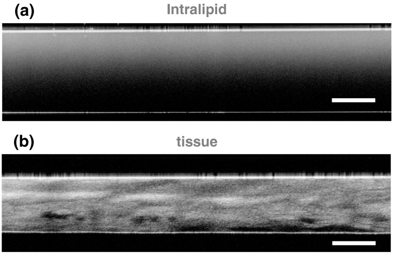
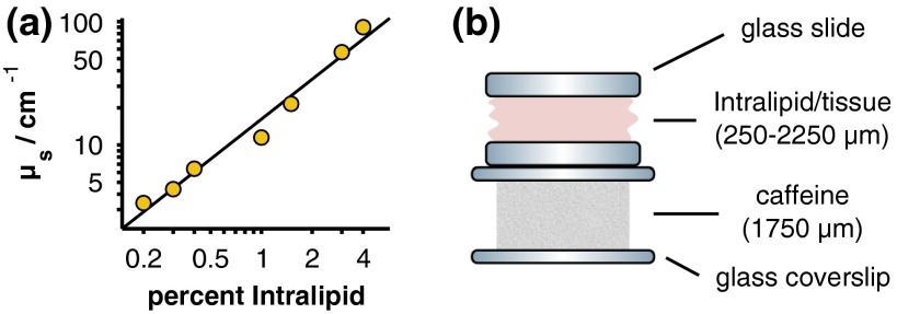
Tissue-simulating Intralipid phantoms, chicken breast tissue, and porcine buccal tissue were each used as turbid scattering samples. The scattering layer was constructed by sandwiching the Intralipid solution (Liposyn II, Hospira, Lake Forest, Illinois) or tissue sample between two glass microscope slides, which facilitated comparison of measurements acquired with different instruments. For the Intralipid phantoms, the glass slides were separated by a physical thickness of , and the concentration of Intralipid was varied between 0.2% and 4.0% ( Intralipid phantoms). A constant thickness across all Intralipid samples was chosen to reduce experimental error in phantom construction. The tissue samples were prepared with a Stadie–Riggs tissue slicer (Thomas Scientific, Swedesboro, New Jersey) and varied in thickness between 250 and ( chicken breast tissue samples) and 250 and ( porcine buccal tissue samples). The optical path length (i.e., ) of each sample was measured with an optical coherence tomography (OCT) system (Spark DRC, Wasatch Photonics Inc., Durham, North Carolina). The refractive index of the Intralipid or tissue sample was then used to convert each measurement to physical length.29 Representative OCT images of an Intralipid phantom and a sample of porcine buccal tissue are shown in Fig. 1.
Fig. 1.
Representative, cross-sectional optical coherence tomography images of (a) Intralipid and (b) porcine buccal tissue samples. The flat reflectors near the top and bottom of each image are the interfaces between the glass microscope slides and the scattering sample. The scale bars represent a physical length of .
The scattering coefficients of the Intralipid phantoms and tissue samples were determined by measuring the on-axis, narrow solid-angle transmission of each sample. An optical power meter (Model 1830-C with 818-ST, Newport Corp., Irvine, California) was placed from the sample holder and illuminated with a 785-nm diode laser (LDCU5, Power Technology Inc., Alexander, Arkansas). An iris with a diameter of 5 mm was placed before the power meter to block any low-angle, forward-scattered light. The reduction in optical power was then measured after inserting each sample into the beam path. The power drop from a sample without an Intralipid or biological tissue scattering layer was also measured to account for attenuation caused by the glass microscope slides. Because the optical properties of Intralipid and biological tissue are dominated by scattering rather than absorption in this wavelength range, scattering coefficients were approximated as , where and are the optical powers measured at the detector with and without the scattering sample, is the thickness of the sample, and ln is the natural logarithm.30 The empirically determined scattering coefficients of the Intralipid samples versus their concentrations are presented in Fig. 2(a). Extrapolating the data to a concentration of 10% Intralipid yields a scattering coefficient of , which is broadly consistent with values reported in the literature.30–32
Fig. 2.
(a) Calculated scattering coefficients for the Intralipid scattering phantoms (yellow circles) along with a linear least-squares fit to the logarithm-transformed data (black line). Error bars are omitted because they are smaller than the size of the markers. (b) Measurement geometry and thicknesses of the scattering sample (Intralipid/tissue) and caffeine powder target.
Two Raman spectrometers were used to study the scattering samples described above: a nonconfocal, slit-based instrument (LabRam ARAMIS, Horiba Jobin Yvon, Edison, New Jersey) fitted with a objective lens (LMPLFLN , Olympus Corp., Center Valley, Pennsylvania) and a coded aperture instrument (MFL-3000, Centice Corp., Morrisville, North Carolina). The technical specifications of the instruments can be found in Table 1. It should be noted that the instruments were configured to approximately match their spectral resolutions and collection numerical apertures (NAs). Differences in instrument performance attributable to the difference in collection areas were then quantified as discussed below.
Table 1.
Technical specifications of the slit-based and coded aperture instruments. Notice that the coded aperture instrument provides a larger collection area than the slit-based instrument ( versus ) while maintaining a similar spectral resolution and collection numerical aperture (NA). This is because of the sharp difference in étendue, which is nearly 6 orders of magnitude greater for the coded aperture instrument.
| Slit based | Coded aperture | |
|---|---|---|
| Illumination wavelength (nm) | 785 | 785 |
| Illumination power (mW) | 10 | 85 |
| Illumination area () | 80 (circular) | (elliptical) |
| Working distance (mm) | 10.6 | 1.5 |
| Spectral resolution () | 10 | 7 |
| Collection NA | 0.5 | 0.45 |
| Collection area () | 52.0 () | () |
| Étendue () | 43.8 |
A pure caffeine powder target ( thickness) was placed beneath each scattering sample as depicted in Fig. 2(b) and spectra were acquired for 10 s (slit-based instrument) or 6 s (coded aperture instrument). The exposure times were chosen to utilize the full dynamic range of each instrument, and the focal plane was fixed at the surface of the caffeine sample (slit-based instrument) or at an optical path depth (i.e., ) of 1.5 mm below the surface of the scattering phantom (coded aperture instrument). Because the Intralipid phantoms were each constructed with a physical thickness of , the focal plane of the slit-based instrument was established with an optically clear 0% sample and remained fixed in place for measurements of the other Intralipid samples. For the tissue measurements, the instrument was focused on the caffeine target in a region adjacent to the edge of the tissue. This region was filled with optically clear saline solution to approximately match the refractive index of the tissue. After focusing the instrument, the sample was laterally translated to the location where the optical path length and scattering coefficient had been previously measured.
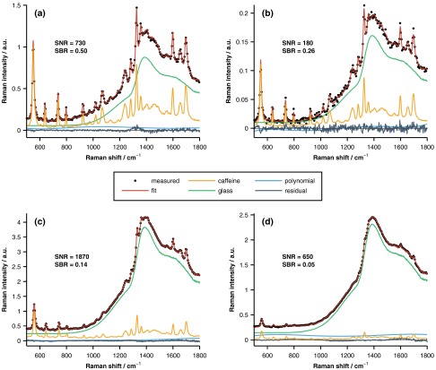
The measured spectra (five per sample per instrument) were least-squares fit with a combination of pure spectra of the underlying components, as well as fifth-order polynomial, in order to determine the spectral contribution of the underlying layer of caffeine. Representative spectra acquired with both the slit-based and coded aperture instruments are displayed in Fig. 3. As shown in Fig. 3, interfering signal from the overlying layer was primarily due to fluorescence from the glass microscope slides. As a reminder, the glass slides were used to aid in phantom construction and to facilitate coregistration of measurements acquired with different instruments. Because this interfering signal was not from caffeine or the overlying turbid layer, the glass fluorescence was modeled and removed prior to all subsequent analyses. The figure shows that the relative caffeine signal measured by the slit-based instrument through the overlying 1%-Intralipid sample drops to whereas the coded aperture system retains of the maximum signal. It should also be noted that both instruments were operated above their detection limits, which were defined as a spectral SNR of unity. The SNR of each measurement was calculated as
| (2) |
where is the spectrum of pure caffeine, is the spectral contribution of the underlying layer of caffeine, and is the wavelength-dependent variance of the measured spectrum. This expression is equal to the caffeine fit coefficient divided by the uncertainty in the coefficient provided that the model components are orthogonal, and the measurement noise is Gaussian, independent, and identically distributed.33 The SNRs varied between 20 and 730 (slit-based instrument) and 230 and 1870 (coded aperture instrument).
Fig. 3.
Representative Raman spectra acquired with the slit-based [(a) and (b)] and coded aperture [(c) and (d)] instruments. The measured data were acquired with a 0% [(a) and (c)] or 1% [(b) and (d)] Intralipid overlayer and are well fit by the pure spectral components as evidenced by the small amplitudes of the fit residuals. The signal-to-noise ratio (SNR) and signal-to-background ratio (SBR) of each representative measurement are also provided.
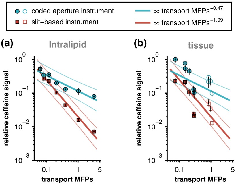
The magnitude of the caffeine signal versus the number of scattering mean free paths () of the overlying Intralipid phantom is plotted in Fig. 4. The signal is plotted on a relative scale, normalized by the signal strength of pure caffeine with a 0% Intralipid overlying layer. The absolute signal strength is not directly compared here because the specific instrument parameters (e.g., illumination power and sensor integration time) are not related to the signal attenuation rates, i.e., these parameters may be varied to increase or decrease absolute signal (or SNR) of either instrument, but not the attenuation rate. Power-law relationships between the MFPs of each phantom and the corresponding caffeine signal measured by each instrument were established by linear least-squares fitting of the logarithm-transformed data. Approximately 90% of the variance in the caffeine signal is described by these fits ( and 0.93 for the coded aperture and slit-based instruments, respectively).
Fig. 4.
Relative caffeine signal versus the number of mean free paths (MFPs) of the overlying Intralipid phantom. The solid lines are power-law fits (along with 95% confidence intervals), and the error bars represent 95% confidence intervals for the mean of each measurement.
In order to compare measurements from the Intralipid and tissue samples, scattering anisotropy must be taken into account. The scattering anisotropy parameter of a material is defined as the average cosine of the scattering angle and varies between zero and one for perfectly isotropic and perfectly forward directional scatterers, respectively. Samples with different scattering anisotropies can be compared by calculating their reduced scattering coefficients: . The number of transport MFPs is then given by . This approximation follows observations that anisotropic scatters behave like isotropic ones with reduced values for their effective scattering coefficients.32 The scattering anisotropy parameters used to calculate the transport MFPs of each sample were 0.65 (Intralipid), 0.97 (chicken breast tissue), and 0.88 (porcine buccal tissue).32,34,35
Similar to Fig. 4, the magnitudes of the caffeine signals measured through each overlying Intralipid phantom are presented in Fig. 5(a). In this case, however, the data are plotted versus the number of transport MFPs and presented on a log-log scale. Like before, a linear least-squares fit was performed on the logarithm-transformed data. Because the transport MFPs of the Intralipid phantoms are equal to their MFPs scaled by 0.35 (i.e., one minus the scattering anisotropy parameter of Intralipid), the coefficients of determination are identical to those reported above ( and 0.93 for the coded aperture and slit-based instruments, respectively). The slopes of the fits to the slit-based and coded aperture data were significantly different () as determined by an analysis of covariance model.
Fig. 5.
Relative caffeine signal versus transport MFPs for the (a) Intralipid phantoms and (b) tissue samples. Data from both the chicken breast (filled markers) and porcine buccal (open markers) tissues are included in panel (b). The solid lines in panel (a) represent linear least-squares fits (along with 95% confidence intervals) of the logarithm-transformed Intralipid data. The Intralipid fits are plotted again in panel (b) for comparison to the tissue data. Error bars represent 95% confidence intervals for the mean of each measurement.
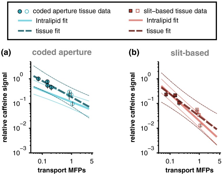
The relationships between measured caffeine signal and the corresponding optical properties of the overlying scattering medium were initially established with Intralipid phantoms because the optical properties of Intralipid are more spatially homogeneous than those of biological tissue (e.g., as shown qualitatively in Fig. 1). The fits relating measured caffeine signal to the number of transport MFPs of the overlying Intralipid phantom are compared with the data acquired from the tissue samples in Fig. 5(b). Although the Intralipid and tissue data show reasonable agreement, the variance in the tissue measurements is not fully described by the relationships established with Intralipid. As mentioned above, this may be partly because of the fact that the optical properties of biological tissue are more heterogeneous than those of Intralipid. In addition, the transport MFPs of the samples were established with collimated transmission measurements that are most accurate in the ballistic or single-scattering regime (i.e., samples with thicknesses corresponding to less than one MFP); therefore, the transport MFPs of the thickest tissues may have been underestimated because of the effects of multiple forward scattering.36,37 If the two thickest samples are omitted (chicken breast samples with thicknesses of 1850 and , which each correspond to greater than 8 MFPs) and a linear least-squares fit is performed on the remaining logarithm-transformed tissue data, strong relationships between transport MFPs and relative caffeine signal are recovered ( and 0.84 for the coded aperture and slit-based instruments, respectively). The least-squares fits to the truncated tissue data are overlaid on the fits to the Intralipid data in Fig. 6. The slopes of the tissue and Intralipid fits associated with each instrument show reasonable agreement and are not significantly different ( for coded aperture data and for slit-based data) as determined by an analysis of covariance model.
Fig. 6.
Comparison of the least-squares fits to the Intralipid data with the corresponding fits to the truncated chicken breast (filled markers) and porcine buccal (open markers) tissue data. The thick lines represent linear least-squares fits (thin lines are 95% confidence intervals) of the logarithm-transformed data and error bars represent 95% confidence intervals for the mean of each measurement. The difference in the slopes of the tissue and Intralipid fits associated with each instrument is not statistically significant.
3. Discussion
Although spontaneous Raman spectroscopy provides high chemical specificity, measuring analyte concentrations with this technique can be difficult because of the relatively small Raman scattering cross section. Acquiring Raman spectra from diffuse sources, such as light returned from highly scattering biological tissue, is even more challenging because the étendue of the Raman-scattered light is often larger than that afforded by traditional slit-based spectrometers. Coded aperture instruments offer a solution to this problem by providing greater étendue without sacrificing spectral resolution. Despite this advantage, it should be noted that some applications require more traditional detection schemes. For example, confocal Raman microscopy offers better spatial resolution and can be used for optical depth-sectioning with lateral and axial resolutions on the micron scale.38 Confocal detection, as well as more recently developed techniques such as SORS, can also be used to preferentially reject interfering signals (e.g., fluorescence or Raman scattering from analytes in the overlying layers) that impart shot noise to the signal of interest.
In this study, two representative spectrometers, one with a slit-based entrance aperture and the other with a coded entrance aperture, were used to study the Raman signal from an analyte as a function of the optical properties of an overlying scattering medium. The results demonstrate that the attenuation in signal intensity versus increased scattering in the overlying layer is more pronounced for the slit-based instrument. As shown in Fig. 5, even at relatively low concentrations of Intralipid (corresponding to 0.2 to 0.4 transport MFPs), the relative signal collected by the coded aperture system was two to three times greater than that collected by the slit-based instrument. After one transport MFP, the signal measured by the slit-based instrument drops to less than 1% while the coded aperture system retains of the maximum signal and only gradually loses further signal with increasing concentrations of Intralipid. Power-law fits to the Intralipid data reveal that the measured analyte signal is approximately proportional to the number of transport MFPs of the scattering sample raised to a power of (coded aperture instrument) or (slit-based instrument).
The performance difference cited above is primarily due to the larger collection area provided by the coded aperture instrument (Table 1). It should be noted that the collection area of the slit-based instrument could be increased by changing the magnification between the sample plane and the entrance plane of the spectrometer and/or increasing the width of the slit. Although this adjustment could reduce the observed difference in relative signal attenuation, it would also negatively impact the collection NA and/or the spectral resolution of the instrument because of the inherent trade-offs between these properties. To be specific, once the optical configuration and width of the entrance slit are fixed, the étendue of the spectrometer, , is completely determined. While changing the magnification between the sample and entrance slit could increase the collection area , if the étendue is preserved, this change would be accompanied by a concomitant decrease in the collection solid-angle and therefore the collection NA []. In order to provide a fair comparison, we chose to approximately match the spectral resolutions and collection NAs of the instruments and then quantify performance differences resulting from the difference in collection areas.
The instruments studied here were chosen to represent extreme cases in order to sharply contrast the difference between an instrument that collects a relatively small number of spatial modes (slit-based) and one that collects many more modes (coded aperture). Collection methods that utilize multielement fiber bundles could potentially bridge the divide between these two approaches. Although SORS is often implemented with fiber bundles, it is a fundamentally different approach that was developed to acquire spectra of subsurface analytes with the depth of interest governed by the offset between illumination and collection regions. In order to improve the sensitivity of a SORS instrument, an annular ring of offset collection fibers centered about the delivery fiber can be used. Assuming shot-noise-limited detection, this would offer a improvement in SNR compared with using a single offset collection fiber. However, this approach would not modify the manner in which the signal from a subsurface region is attenuated because of an overlying layer.7 An alternative implementation is to use a fiber bundle to simultaneously collect spectra at multiple spatial offsets. Various computational algorithms can then be used to extract spectra of analytes present at different depths.26
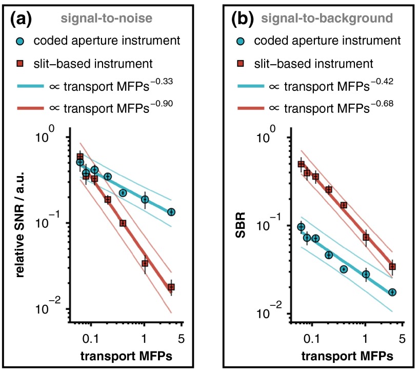
This study reports the generalizable relationship between relative analyte signal and the transport MFPs of an overlying scattering medium. It should be noted, however, that the ability to accurately quantify analyte concentrations or biochemical tissue properties depends not upon absolute signal levels, but rather on signal-to-background ratios (SBRs) and SNRs. Because these metrics depend on the Raman scattering and fluorescence cross sections of the sample constituents as well as specific instrument parameters, it is not possible to provide universally applicable, quantitative estimates of these ratios. The specific SBR and SNR associated with our measurements of caffeine through overlying Intralipid phantoms are provided in Fig. 7, where the signal strength was quantified by calculating the spectral contribution from caffeine. This figure shows that regardless of which metric is used, the response of the coded aperture system decays more slowly than that of the slit-based instrument with increasing scattering in the overlying layer. Unlike these metrics, the attenuation in relative signal intensity is more broadly applicable because it specifies the performance of a given detection modality for any analyte, regardless of variations in Raman scattering cross sections.
Fig. 7.
(a) Relative SNR and (b) SBR associated with each measurement of caffeine through an overlying Intralipid phantom. The SNR is plotted on a relative scale, normalized by the SNR of pure caffeine with a 0% Intralipid overlayer. Notice that the slit-based spectrometer produced superior SBRs from the moderate depth selectively provided by the narrow entrance slit. The solid lines represent linear least-squares fits (along with 95% confidence intervals) of the logarithm-transformed data, and the error bars represent 95% confidence intervals for the mean of each measurement.
In summary, the results of this work establish the quantitative relationships between the optical properties of an overlying scattering medium and the analyte signal measured by two representative spectrometers: one with a traditional slit-based entrance aperture and the other with a coded entrance aperture. Although the sensing capacity is dependent upon the specific instrumentation (e.g., the étendue of the instrument as determined by the geometry of the entrance aperture and by the upstream optics including the objective and tube lenses), the results shown here qualitatively highlight how analyte signal detection through scattering media depends on instrument étendue. Broadly speaking, coded aperture instruments have the greatest utility in applications where: (1) the étendue of the source is larger than that of more traditional detection schemes (e.g., slit based, confocal); (2) micron-level spatial resolution is not required; and (3) preferential rejection of interfering signals from overlying layers is not required (e.g., as provided by confocal microscopy and SORS). These findings should be informative to spectroscopists selecting instruments for studies of analytes beneath turbid media.
Acknowledgments
Financial support was provided by the National Institutes of Health (R01 HD072702) and the National Science Foundation (CBET 1133222).
Biographies
Jason R. Maher joined the Biomedical Engineering Department at Duke University as a postdoctoral associate after receiving his PhD in optics from the University of Rochester in 2013. His research interests include biomedical optical spectroscopy, interferometry, and imaging for monitoring disease and spatiotemporal distributions of analytes in biological tissue.
Thomas E. Matthews earned his PhD in chemistry at Duke University in the Warren Group, where he worked on new methods of pump-probe microscopy for melanoma diagnosis. Later, as a postdoctoral researcher in the Wax Group at Duke University, he developed multispectral, multiple scattering low coherence interferometry for deep tissue imaging. He is currently at Biogen Idec implementing Raman spectroscopy and other optical methods for advanced process control in biopharmaceutical development.
Ashley K. Reid is earning her BSE in biomedical engineering at Duke University. She spent last summer volunteering with Engineering World Health repairing medical equipment in Tanzanian hospitals. In addition to optical spectroscopy, she has conducted research in synthetic biology through Duke’s International Genetically Engineered Machines Team. She is chief of outreach of the Nonprofit Girls Engineering Change, working to reduce the gender gap in STEM through hands-on engineering workshops.
David F. Katz is the Nello L. Teer, Jr. professor of biomedical engineering and professor of obstetrics and gynecology at Duke University. His research interests emphasize women’s health, with a focus on sexually transmitted infections and contraception. Current work emphasizes delivery of molecules that inhibit infection by HIV, and includes both deterministic computational modeling and new experimental techniques that measure transport properties of new drugs and HIV virions, and their interactions.
Adam Wax joined the faculty of the Biomedical Engineering Department at Duke University as an assistant professor in 2002 and was promoted to associate professor in 2008. He received his PhD in physics from Duke in 1999 and completed his postdoctoral training at MIT. His research interests include optical spectroscopy for early cancer detection, novel microscopy and interferometry techniques.
References
- 1.Krafft C., Sergo V., “Biomedical applications of Raman and infrared spectroscopy to diagnose tissues,” Spectrosc.-Int. J. 20(5–6), 195–218 (2006). 10.1155/2006/738186 [DOI] [Google Scholar]
- 2.Hanlon E. B., et al. , “Prospects for in vivo Raman spectroscopy,” Phys. Med. Biol. 45(2), R1–R59 (2000). 10.1088/0031-9155/45/2/201 [DOI] [PubMed] [Google Scholar]
- 3.Mahadevan-Jansen A., Richards-Kortum R. R., “Raman spectroscopy for the detection of cancers and precancers,” J. Biomed. Opt. 1(1), 31–70 (1996). 10.1117/12.227815 [DOI] [PubMed] [Google Scholar]
- 4.Stone N., et al. , “Raman spectroscopy for identification of epithelial cancers,” Faraday Discuss. 126, 141–157; discussion 169–183 (2004). 10.1039/b304992b [DOI] [PubMed] [Google Scholar]
- 5.Motz J. T., et al. , “Optical fiber probe for biomedical Raman spectroscopy,” Appl. Opt. 43(3), 542–554 (2004). 10.1364/AO.43.000542 [DOI] [PubMed] [Google Scholar]
- 6.Latka I., et al. , “Fiber optic probes for linear and nonlinear Raman applications–current trends and future development,” Laser Photonics Rev. 7(5), 698–731 (2013). 10.1002/lpor.2013.7.issue-5 [DOI] [Google Scholar]
- 7.Matousek P., et al. , “Subsurface probing in diffusely scattering media using spatially offset Raman spectroscopy,” Appl. Spectrosc. 59(4), 393–400 (2005). 10.1366/0003702053641450 [DOI] [PubMed] [Google Scholar]
- 8.Matousek P., et al. , “Numerical simulations of subsurface probing in diffusely scattering media using spatially offset Raman spectroscopy,” Appl. Spectrosc. 59(12), 1485–1492 (2005). 10.1366/000370205775142548 [DOI] [PubMed] [Google Scholar]
- 9.Matousek P., “Inverse spatially offset Raman spectroscopy for deep noninvasive probing of turbid media,” Appl. Spectrosc. 60(11), 1341–1347 (2006). 10.1366/000370206778999102 [DOI] [PubMed] [Google Scholar]
- 10.Schulmerich M. V., et al. , “Subsurface Raman spectroscopy and mapping using a globally illuminated non-confocal fiber-optic array probe in the presence of Raman photon migration,” Appl. Spectrosc. 60(2), 109–114 (2006). 10.1366/000370206776023340 [DOI] [PubMed] [Google Scholar]
- 11.Macleod N. A., et al. , “Prediction of sublayer depth in turbid media using spatially offset Raman spectroscopy,” Anal. Chem. 80(21), 8146–8152 (2008). 10.1021/ac801219a [DOI] [PubMed] [Google Scholar]
- 12.Maher J. R., Berger A. J., “Determination of ideal offset for spatially offset Raman spectroscopy,” Appl. Spectrosc. 64(1), 61–65 (2010). 10.1366/000370210790571936 [DOI] [PubMed] [Google Scholar]
- 13.Reble C., et al. , “Influence of tissue absorption and scattering on the depth dependent sensitivity of Raman fiber probes investigated by Monte Carlo simulations,” Biomed. Opt. Express 2(3), 520–532 (2011). 10.1364/BOE.2.000520 [DOI] [PMC free article] [PubMed] [Google Scholar]
- 14.Matousek P., Stone N., “Prospects for the diagnosis of breast cancer by noninvasive probing of calcifications using transmission Raman spectroscopy,” J. Biomed. Opt. 12(2), 024008 (2007). 10.1117/1.2718934 [DOI] [PubMed] [Google Scholar]
- 15.Yuen J. M., et al. , “Transcutaneous glucose sensing by surface-enhanced spatially offset Raman spectroscopy in a rat model,” Anal. Chem. 82(20), 8382–8385 (2010). 10.1021/ac101951j [DOI] [PMC free article] [PubMed] [Google Scholar]
- 16.Matousek P., et al. , “Depth profiling in diffusely scattering media using Raman spectroscopy and picosecond Kerr gating,” Appl. Spectrosc. 59(2), 200–205 (2005). 10.1366/0003702053085115 [DOI] [PubMed] [Google Scholar]
- 17.Matousek P., Stone N., “Recent advances in the development of Raman spectroscopy for deep non-invasive medical diagnosis,” J. Biophotonics 6(1), 7–19 (2013). 10.1002/jbio.201200141 [DOI] [PubMed] [Google Scholar]
- 18.Golay M. J. E., “Multi-slit spectrometry,” J. Opt. Soc. Am. 39(6), 437–444 (1949). 10.1364/JOSA.39.000437 [DOI] [PubMed] [Google Scholar]
- 19.Gehm M. E., et al. , “Static two-dimensional aperture coding for multimodal multiplex spectroscopy,” Appl. Opt. 45(13), 2965–2974 (2006). 10.1364/AO.45.002965 [DOI] [PubMed] [Google Scholar]
- 20.Wagadarikar A. A., Gehm M. E., Brady D. J., “Performance comparison of aperture codes for multimodal, multiplex spectroscopy,” Appl. Opt. 46(22), 4932–4942 (2007). 10.1364/AO.46.004932 [DOI] [PubMed] [Google Scholar]
- 21.Gehm M. E., et al. , “High-throughput, multiplexed pushbroom hyperspectral microscopy,” Opt. Express 16(15), 11032–11043 (2008). 10.1364/OE.16.011032 [DOI] [PubMed] [Google Scholar]
- 22.Barducci A., et al. , “Radiometric and signal-to-noise ratio properties of multiplex dispersive spectrometry,” Appl. Opt. 49(28), 5366–5373 (2010). 10.1364/AO.49.005366 [DOI] [PubMed] [Google Scholar]
- 23.McCain S. T., et al. , “Coded aperture Raman spectroscopy for quantitative measurements of ethanol in a tissue phantom,” Appl. Spectrosc. 60(6), 663–671 (2006). 10.1366/000370206777670693 [DOI] [PubMed] [Google Scholar]
- 24.Dingari N. C., et al. , “Investigation of the specificity of Raman spectroscopy in non-invasive blood glucose measurements,” Anal. Bioanal. Chem. 400(9), 2871–2880 (2011). 10.1007/s00216-011-5004-5 [DOI] [PMC free article] [PubMed] [Google Scholar]
- 25.Keller M. D., Majumder S. K., Mahadevan-Lansen A., “Spatially offset Raman spectroscopy of layered soft tissues,” Opt. Lett. 34(7), 926–928 (2009). 10.1364/OL.34.000926 [DOI] [PubMed] [Google Scholar]
- 26.Maher J. R., et al. , “Overconstrained library-based fitting method reveals age- and disease-related differences in transcutaneous Raman spectra of murine bones,” J. Biomed. Opt. 18(7), 077001 (2013). 10.1117/1.JBO.18.7.077001 [DOI] [PMC free article] [PubMed] [Google Scholar]
- 27.Chuchuen O., et al. , “Quantitative analysis of microbicide concentrations in fluids, gels and tissues using confocal Raman spectroscopy,” PLOS One 8(12), e85124 (2013). 10.1371/journal.pone.0085124 [DOI] [PMC free article] [PubMed] [Google Scholar]
- 28.Gao Y. J., Katz D. F., “Multicompartmental pharmacokinetic model of tenofovir delivery by a vaginal gel,” PLOS One 8(9), e74404 (2013). 10.1371/annotation/f03fa448-2129-414a-b841-031ea683d965 [DOI] [PMC free article] [PubMed] [Google Scholar]
- 29.Ding H. F., et al. , “Determination of refractive indices of porcine skin tissues and Intralipid at eight wavelengths between 325 and 1557 nm,” J. Opt. Soc. Am. A 22(6), 1151–1157 (2005). 10.1364/JOSAA.22.001151 [DOI] [PubMed] [Google Scholar]
- 30.Vanstaveren H. J., et al. , “Light scattering in Intralipid-10% in the wavelength range of 400–1100 nm,” Appl. Opt. 30(31), 4507–4514 (1991). 10.1364/AO.30.004507 [DOI] [PubMed] [Google Scholar]
- 31.Flock S. T., et al. , “Optical-properties of intralipid—a phantom medium for light-propagation studies,” Laser Surg. Med. 12(5), 510–519 (1992). 10.1002/(ISSN)1096-9101 [DOI] [PubMed] [Google Scholar]
- 32.Pogue B. W., Patterson M. S., “Review of tissue simulating phantoms for optical spectroscopy, imaging and dosimetry,” J. Biomed. Opt. 11(4), 041102 (2006). 10.1117/1.2335429 [DOI] [PubMed] [Google Scholar]
- 33.Scepanovic O. R., et al. , “Determination of uncertainty in parameters extracted from single spectroscopic measurements,” J. Biomed. Opt. 12(6), 064012 (2007). 10.1117/1.2815692 [DOI] [PubMed] [Google Scholar]
- 34.Cheong W. F., Prahl S. A., Welch A. J., “A review of the optical-properties of biological tissues,” IEEE J. Quantum Electron. 26(12), 2166–2185 (1990). 10.1109/3.64354 [DOI] [Google Scholar]
- 35.Bashkatov A. N., Genina E. A., Tuchin V. V., “Optical properties of skin, subcutaneous, and muscle tissues: a review,” J. Innov. Opt. Heal Sci. 4(1), 9–38 (2011). 10.1142/S1793545811001319 [DOI] [Google Scholar]
- 36.Ishimaru A., Wave Propagation and Scattering in Random Media, pp. 260–266, Academic Press, New York: (1978). [Google Scholar]
- 37.Yaroshevsky A., et al. , “Transition from the ballistic to the diffusive regime in a turbid medium,” Opt. Lett. 36(8), 1395–1397 (2011). 10.1364/OL.36.001395 [DOI] [PubMed] [Google Scholar]
- 38.Caspers P. J., et al. , “In vivo confocal Raman microspectroscopy of the skin: noninvasive determination of molecular concentration profiles,” J. Invest. Dermatol. 116(3), 434–442 (2001). 10.1046/j.1523-1747.2001.01258.x [DOI] [PubMed] [Google Scholar]


