Abstract
In this study, a novel droplet based microfluidic method for the generation of different sized droplet interface bilayers is reported. A microfluidic platform was designed, which allows the generation and packing of picoliter lipid coated water droplets. Droplets were generated by hydrodynamic focusing coupled with selective transport along grooves according to their size. A trapping structure at the end of the groove and a fine control of the flow pressures allowed for the droplets to be successfully trapped and aligned on demand. This technology facilitates the fine control of droplet size production as well as the generation of extended networks from a variety of lipids including 1,2-diphytanoyl-sn-glycero-3-phosphocholine and 1,2-dioleoyl-sn-glycero-3-phosphocholine in linear and non-linear configurations, which is vital to the application of Droplet Interface Bilayers to biological network construction on-chip.
I. INTRODUCTION
Recently, a wide variety of studies have emerged with the purpose of building droplet interface bilayers in a reproducible manner as a tool for studying the biophysical properties of artificial lipid bilayers. Several methods have been previously reported for the formation of lipid bilayers using droplet technologies and compiled in different reviews.1,2 One of the first systems was developed by Funakoshi et al. and Holden et al.3,4 in which bilayer generation occurred when bringing together two or more aqueous droplets submerged in an oil environment in a lipid stabilized aqueous–oil interface. Other approaches developed by the Bayley group5,6 managed to form networks of tens of droplets and use them to process electrical inputs.7 They also demonstrated the application of droplet networks for power generation, light sensing, and ion channel screening.1 Other well-known methods such as dielectrophoresis formation and electrowetting8,9 have been demonstrated to successfully generate functional interface bilayers while presenting limitations regarding the maximum number of droplets aligned. More recent work of Zagnoni and Cooper10 demonstrated a passive droplet arraying and shifting method for the formation of lipid bilayers, which allowed the controllable creation of droplet interfaces.
Previous work from our laboratory has also focused on the development of techniques for Droplet Interface Bilayer (DIB) formation.11 DIB networks were generated via high-throughput generation of microdroplets, leading to 3-dimensional DIB arrays—this technology was limited to DIB network storage within tubing.
Recent advances in generating millifluidic DIBs in trapping structures built with a 3D printer have also been reported.12 The work developed by King et al. presents limitations with respect to the maximum number of droplets that can be trapped per row as well as the high dimensions and lipid concentrations of the droplets. Droplets of 500–800 μm diameter were generated and packed as linear arrays of 2–9 droplets with a lipid concentration of 40 mg/ml.
Addressing the current lack of microfluidic strategies for manufacturing multiple droplet interface bilayers, we describe a system for the controlled generation of different sized DIBs on demand. Different from the previously reported DIB platforms based on grooves,12 this multifunctional device has a very simple design that enables the user to transport lipid coated droplets controllably according to size. Droplet interface bilayers between droplets of approximately 80 and 160 μm were formed using a lipid concentration of 2 mg/ml. This device is also able to generate networks of DIBs in pre-defined structures resulting in rows along with predetermined grouping of droplets. By changing the diameter size of the containment vessels, a wide range of packing numbers and interface configurations can be achieved. Additionally, this platform incorporates two inlets to generate droplets of different compositions, which increases the flexibility of the device to form asymmetric DIBs and form nonlinear sequences of droplets, making possible the use of this platform as a mass transfer study device.
II. WORKING PRINCIPLE
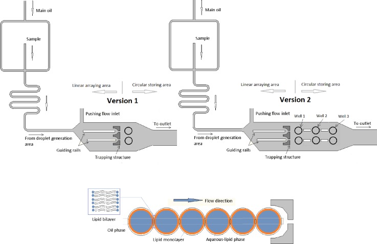
The device consists of a generation area, a linear arraying area, and a circular packing area (Figure 1). Lipid coated droplets were generated by hydrodynamic flow focusing and stabilized along a meander till they reached the linear arraying area. In the linear arraying area, they were transported to either the first or the second rail by adjusting the flow pressure of the pushing inlet.
FIG. 1.
Schematic of the different size droplet interface bilayer design. Version 1 of the device contains one well per sorting rail and version 2 of the device contains three wells interconnected by short rails.
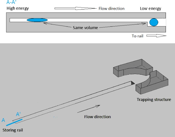
Droplets were generated flattened at the rectangular cross section of the channels; therefore, they were constrained to a high surface energy shape, which then encouraged their translocation when approaching a rail. This is due to the fact that, for a droplet of constant volume, the interfacial energy is minimal in a spherical shape and it increases as the drop flattens into a pancake shape. Consequentially, when each of the sorted droplets approaches their guiding rail they are driven to enter said cavity so as to lower their interfacial energy (see Figures 2 and 3).
FIG. 2.
Schematic of the 3D design for a single rail trapping structure. Top: Schematic of the railing principle. Cross section along A-A′.
FIG. 3.

Cross section along A-A′ direction for a two rail platform device.
The size of the generated droplets was controlled by adjusting the relative flow rate values between the pushing and the main oil flows with one or the other remaining constant in one of two operational modes. When operating the chip under the first mode, the pushing flow is maintained fixed, and the increase of the main oil pressure flow generated smaller droplets on the first rail and bigger droplets on the second rail as the main oil pressure was released. If the main oil flow pressure was kept constant (second mode), variation of the pushing flow generated smaller droplets on the second rail and bigger droplets on the first rail.
When droplets reached the trapping structures (see Figure 1), they could be stopped on the demand at a given trapping structure or allowed to keep on moving thereby filling the wells located just after the trapping structure. When droplets were allowed to flow and fill the wells, they would accumulate progressively and droplet interface bilayers would form with different areas depending on the number of droplets packed onto the site and the size of the generated droplet in each well. Therefore, by stopping the flow lipid coated droplets could be made to accumulate either along the rails or wells, forming different size droplet interface bilayers in each case.
III. MATERIALS AND METHODS
A. Chemicals
Mineral oil (Sigma Aldrich) was used as the main oil carrier for the generation of the lipid coated droplets. Sudan red dye (Sigma Aldrich) was used to color the oil and facilitate the visualization of the flow rates on chip. Deionized water was used to prepare the lipid-in solution. All lipids were purchased from Avanti Polar Lipids as powders.
Experiments were performed using either 1,2-diphytanoyl-sn-glycero-3-phosphocholine (DPhPC) or 1,2-dioleoyl-sn-glycero-3-phosphocholine (DOPC) (Avanti Polar lipids). They were used to prepare the solutions in a concentration of 2 mg/ml.
B. Microfabrication
The microfluidic device structure mask was designed using AutoCAD 2010 software (Autodesk) and printed under darkfield polarity. The chip features were microfabricated silicon wafers (IDB Technologies Ltd., Whitley, UK) using standard two step soft lithography techniques. SU-8 50 (Chestech Ltd., Rugby, UK) was used as the master photoresist and was deposited twice to a thickness of 50 mm, which defined the two different heights of the channel. Microposit EC-Solvent (Chestech Ltd., Rugby, UK) was used to remove unexposed resist, and isopropylalcohol and distilled water were used for rinsing the substrate. Polydimethylsiloxane (PDMS) was then poured over the master and cured (5 h at 65 °C). The PDMS device was sealed on another PDMS slide by plasma bonding to increase the hydrophobicity of the platform.
The holes used to provide access for the tubing were manufactured using disposable biopsy punches (Kai medical, UK). The device was connected to open syringes by silicone tubing (2 mm) (VWR, UK) and pieces of PTFE tubing (Cole Parmer, UK) acting as connectors.
Both guiding and trapping structures were manufactured on the same PDMS part. The meander length is approximately 8 mm. Channels are 100 μm wide and 50 μm deep so the generated droplets were flattened. Guiding tracks are manufactured in 50 × 50 μm.
Version one included a well adjacent to the rail of 220 μm diameter. Version 2 comprised an extended version of the design includes interconnected wells, each 220 μm diameter with rails joining them in order to be able to subsequently fill the vessels and increase the device flexibility.
C. Instrumentation
The samples were filled in reservoirs formed from barrels of 10 ml disposable plastic syringes (Becton Dickinson, UK). Open syringes were connected to the silicone tubing by BD needles G24 (Becton Dickinson, UK). Gravity was used as the driving force with liquid pressure within the microdevice therefore controlled by the heights of the open syringes.
The pushing flow was delivered to the microdevice by changing the relative height of the reservoir connected to the pushing inlet. PTFE and silicone tubing (2 mm OD) (VWR, UK) were used to interface the reservoirs to the chip. The images were recorded using Motic Stereoscope (Motic, Spain) and Moticam 2.0 (Motic, Spain).
III. RESULTS
To enable the generation of arrays of DIBs built up from different sized droplets (range of picoliters), flattened droplets were first produced by hydrodynamic focusing. Continuous generation of droplets was achieved by adjusting the flow pressures such that the lipid aqueous sample breaks into droplets of the desired shape at a user defined production rate (20–90 droplets/min). These droplets flowed along the meander for stabilization purposes and deflected to one or another rail depending on flow rate variations of the pushing flow.
Preliminary experiments were focused on the ability of transporting different size droplets into different rails. This was successfully achieved as shown in Figure 3. For a given rail, droplet size could be controlled by adjusting the relative flows between the main oil flow and the pushing flow pressure. The initial flow rates were set such that the stream of generated droplets flowed along rail 1 (see Figure 3). As the pushing flow pressure was increased, smaller droplets were produced and driven towards rail 2 (Figure 3) by hydrodynamic forces.
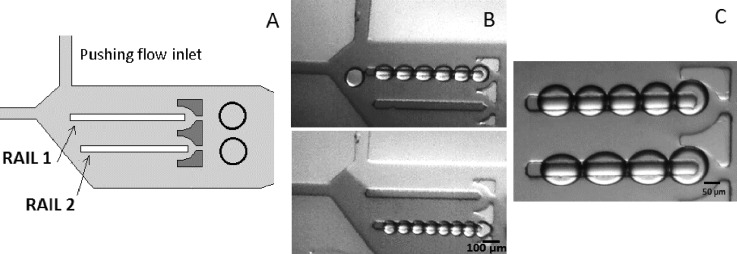
Additionally, flow rates can be slowed down so that trapping of different sized droplets is achieved, and therefore, different DIB size formation was performed simultaneously on both rails (Fig. 4).
FIG. 4.
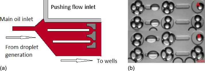
Droplet interface bilayer formation in rails after droplets being sorted in two different tracks using DOPC. (a) Schematic of the microfluidic platform. (b) Individual sorting of droplets. (c) Droplets arrayed in different sizes simultaneously.
Once droplets entered the rails and encountered the trapping structure they would come to a standstill if the flow rates were sufficiently low or stop-flow conditions were applied allowing them to systematically accumulate along the rail and form a series of DIB interfaces.
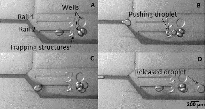
In a continuous flow regime, droplets were guided along the corresponding rail and passed through the neck of the trapping structure thereby entering the first well. As mentioned previously, adjustment of the flow rates offered control of the size of the droplets. Depending on the size the generated droplet, a given well was able to accommodate between 1 and 5 lipid coated droplets arranged in a 2-D circular manner configuration forming a sequence of droplet interface bilayers in tandem. Figure 5 shows frames extracted from recorded videos when flow rates were set to trap two droplets in a continuous flow regime. Generated droplets had a diameter of approximately 150 μm and were produced at 80 droplets/min. Droplets were produced and driven to flow along rail 2. Each generated droplet entered first the rail and then slowed down at the trapping structure and the well due to the change of droplet surface energy. The next generated droplet formed a bilayer when reaching the well by entering into contact with the previous droplet and pushing it to the outlet.
FIG. 5.
Formation of two droplet interface bilayers in the well area using DPhPC. A (t = 0 s), B (t = 0.5 s), C (t = 1 s), and D (t = 1.5 s). Red dyed oil (in dark) was used to color the main carrier oil.
Experiments performed using version 1 of the device showed the capability to selectively guide droplets through the trapping structure and along a rail into the adjacent well, forming different droplet interface bilayer configurations depending on the size of the incoming droplets. Further experiments were performed using version 2 of the device, which included three interconnected aligned wells. Version 2 of the device was designed so that droplets would follow the flow filling the rails and wells in a consecutive manner, leading to the progressive occupation of a series of aligned wells (Figure 1). The maximum number of packed droplets per well was determined by the ratio of the size of the droplets to a given well diameter.
Figure 6 shows how droplets can be arrayed forming droplet interface bilayers both in the rails and well regions of the chip. By varying the size of the incoming droplets, the configuration of the droplets in the wells is modified and the number of droplets trapped on a rail controlled.
FIG. 6.

Droplet interface bilayers in a single rail for different size/packing using DPhPC. A and B frames show the stop flow conditions for an experiment set for packing three and four droplets maximum, respectively. Size of droplets in frame A is approximately 120 μm and size of droplets in frame B is 100 μm.
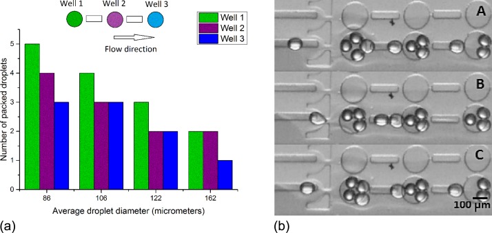
Similarly to version 1, droplets would flow along the rail and reach the well progressively filling them for different droplet sizes. The interconnecting rails were designed to guide the released droplets from one well to another. In this way, droplets would fill the first well according to the maximum of the packing capacity for a given droplet size (Figure 7) and then gradually filling in the neighboring wells decreasing the packing numbers as flow would be slowed down in the interconnecting rails and wells. Figure 6 shows the relationship between the size of the generated droplets and the number of packed droplets in each well. Five experimental measurements were performed, giving identical results. It is observed that the smaller the droplet the major number of packing combinations, while as the droplet size comes closer to the well size, the number of packed droplets decreases.
FIG. 7.
Packing capacity for the version 2 of the device per well for different droplets sizes on stop-flow regime conditions using DPhPC. A, B, and C show captions of continuous flow conditions for 80 μm average droplet diameter (A t = 0 s, B t = 0.2 s, and C = 0.4 s).
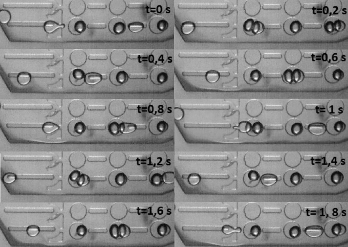
When experiments were run for a two droplet packing condition the device presented an ordered interchange of bilayers. The first generated droplets filled the wells one by one. Once all the three wells were filled, the entering droplet formed a bilayer on the first well by entering into contact with the existing droplet in the well. Due to the continuous action of the running flow, the entering droplet pushed the static droplet. The expulsed droplet flowed along the interconnecting rail and entered the second well coming into contact with the existing droplet and forming a bilayer, and pushing it to the second well. This process applies to the third well too, forming a train of bilayer interchanges. Frames extracted from the recorded videos showing this effect are compiled in Figure 8.
FIG. 8.
Successive and ordered interchange of interface bilayers for a two droplet packing configuration for a chained interchange of bilayers for 1.8 s using DPhPC.
Complementary experiments were also performed without using the pushing flow. When the pushing flow was blocked, generated equally sized droplets entered the free flow area and chose a random track to follow. Most of the generated droplets would enter the tracks and form droplet interface bilayers simultaneously in both rails (Figure 9).
FIG. 9.
Left: Schematic of oil flow interface position for the formation of droplet interface bilayers in two rails simultaneously without pushing flow using DPhPC. Right: A and B show captions for the stop flow condition for experiments set for four and three droplet packing conditions, respectively.
Furthermore, as the well size is fixed, when a droplet leaves the rail to enter the well induces another one to pass to the next well, and a gradient of number of packed droplets per well is generated. Therefore, when stopping the flow, droplet interface bilayers will form in different sizes depending on the well in which they are trapped. With the given geometry droplets were able to be generated and packed in diameter sizes ranging from approximately 80 μm to 170 μm (Figure 9).
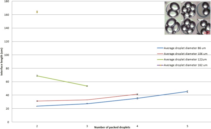
Experiments were run to measure the interface length in different configurations using Image J software. Interface length refers to the magnitude of the projection of the droplet-droplet contact interface on the plane of measurement. It was observed that for droplets below 120 μm the interface length increased as the number of droplets packed increased. Oppositely, for droplets over 120 μm, larger DIBs were achieved when they were packed in pairs and then decreased as the number of droplets per well increased.
Figure 10 shows the droplet interface bilayer length for different droplet diameter and packing configurations.
FIG. 10.
Droplet interface bilayer length for different droplet diameters and packing configurations using DPhPC (well size 220 μm diameter) (N = 5).
Five droplet measurements were performed. Droplets with an average diameter of 162 μm could only pack by pairs; droplets for 122 μm diameter could pack in pairs and in groups of three. When the droplet size was around 106 μm, droplets can be trapped in pairs, and in groups of three or four and for smaller droplets with average diameter of 86 μm, droplets can be trapped in groups of 2, 3, 4, or 5.
As DIBs of different sizes can be formed by altering packing configurations using droplets of the same size it is therefore possible to create different sized DIBs in one run without any flow variations.
There are some clear advantages of forming DIBs in the wells compared to the formation of DIBs in the rails. One of them is that, opposite to the rail trapping DIB formation, when droplets reach the well, they recover a spherical shape as the size of the well is bigger than the maximum diameter of the generated droplet, reducing the possible stretching of the lipid membrane by the interactions of droplet surface with the channel and therefore, increasing the stability of the bilayer.13 Additionally, this device allows the flow rated to be controlled to approach the droplets as slow as possible while forming the bilayer, representing an improved system for DIB formation.
DIB formation was confirmed on chip by using a device with two inlets designed to allow the formation of droplets with varying composition so as to provide a platform for demonstrating mass transfer across the bilayer. For this purpose, a single groove on the design was loaded with two droplets of different composition to form a lipid bilayer.
Chemical permeability assays have already been performed through DIBs.14 The presented assay demonstrated the reaction of hydrogen peroxide in the presence of horseradish peroxidase (HRP), with Amplex Red reagent (Invitrogen Ltd., Paisley, UK) to generate the red-fluorescent oxidation product, resorufin. Upon arraying of the heterogeneous droplet train, transport phenomena, in this case of hydrogen peroxide, across the surfactant bilayers was observed, thereby confirming DIB formation.15 Figure 11 shows the results demonstrating that hydrogen peroxide can transfer across the bilayer and initiate the enzymatic reaction in seconds. The change of fluorescence was measured to demonstrate the progression of the reaction. Further experiments are being carried out to study the effect of the concentration of H2O2 on the kinetics of the reaction.
FIG. 11.

Hydrogen peroxide transfer through the bilayer using Amplex red reagent and DPhPC. The graph shows the increase of the measured fluorescence intensity over time on the Amplex red containing droplet as the reaction takes place.
The versatility of the presented system enables us to generate extended networks from a variety of lipids including DPhPC and DOPC in different sizes. This strategy facilitates not only the fine control of droplet interface bilayer size and location but also the study of molecular communications across the interface. In conclusion, this paper describes a novel technology for the generation of droplet interface bilayers in a variety of shapes and configurations, increasing their potential application in areas such as drug discovery.
ACKNOWLEDGMENTS
This work was supported by EPSRC Grant Nos. EP/G00465X/1 and EP/J017566/1
References
- 1.Bayley H., Cronin B., Heron A., Holden M. A., Hwang W. L., Syeda R., Thompson J., and Wallace M., Mol. BioSyst. 4, 1191–1208 (2008). 10.1039/b808893d [DOI] [PMC free article] [PubMed] [Google Scholar]
- 2.Villar G. and Bailey H., Encyclopedia of Biophysics ( Springer, 2012). [Google Scholar]
- 3.Funakoshi K., Suzuki H., and Takeuchi S., Anal. Chem. 78, 8169–8174 (2006). 10.1021/ac0613479 [DOI] [PubMed] [Google Scholar]
- 4.Holden M. A., Needham D., and Bayley H., J. Am. Chem. Soc. 129, 8650–8655 (2007). 10.1021/ja072292a [DOI] [PubMed] [Google Scholar]
- 5.Hwang W. L., Chen M., Cronin B., Holden M. A., and Bayley H., J. Am. Chem. Soc. 130, 5878–5879 (2008). 10.1021/ja802089s [DOI] [PubMed] [Google Scholar]
- 6.Hwang W. L., Holden M. A., White S., and Bayley H., J. Am. Chem. Soc. 129, 11854–11864 (2007). 10.1021/ja074071a [DOI] [PubMed] [Google Scholar]
- 7.Maglia G., Heron A. J., Hwang W. L., Holden M. A., Mikhailova E., Li Q., Cheley S., and Bayley H., Nat. Nanotechnol. 4, 437–440 (2009). 10.1038/nnano.2009.121 [DOI] [PubMed] [Google Scholar]
- 8.Aghdaei S., Sandison M. E., Zagnoni M., Green N. G., and Morgan H., Lab Chip 8, 1617–1620 (2008). 10.1039/b807374k [DOI] [PubMed] [Google Scholar]
- 9.Poulos J. L., Nelson W. C., Jeon T.-J., Kim C.-J., and Schmidt J. J., Appl. Phys. Lett. 95, 013706 (2009). 10.1063/1.3167283 [DOI] [Google Scholar]
- 10.Zagnoni M. and Cooper J. M., Lab Chip 10, 3069–3073 (2010). 10.1039/c0lc00219d [DOI] [PubMed] [Google Scholar]
- 11.Elani Y., deMello A. J., Niu X., and Ces O., Lab Chip 12, 3514–3520 (2012). 10.1039/c2lc40287d [DOI] [PubMed] [Google Scholar]
- 12.King P. H., Jones G., Morgan H., Planque M. R. R. de, and Zauner K. P., Lab Chip 14, 722–729 (2014). 10.1039/c3lc51072g [DOI] [PubMed] [Google Scholar]
- 13.Stanley C. E., Elvira K. S., Niu X. Z., Gee A. D., Ces O., Edel J. B., and deMello A. J.. Chem. Commun. 46, 1620–1622 (2010). 10.1039/b924897h [DOI] [PubMed] [Google Scholar]
- 14.Nisisako T.et al. , Analyst 138, 6793 (2013). 10.1039/c3an01314f [DOI] [PubMed] [Google Scholar]
- 15.Bai Y., He X., Liu D., Patil S. N., Bratton D., Huebner A., Hollfelder F., Abell C., and Huck W. T. S., Lab Chip 10, 1281–1285 (2010). 10.1039/b925133b [DOI] [PubMed] [Google Scholar]


