Abstract

Clinical medicine and public health would benefit from simplified acquisition of biological samples from patients that can be easily obtained at point of care, in the field, and by patients themselves. Microneedle patches are designed to serve this need by collecting dermal interstitial fluid containing biomarkers without the dangers, pain, or expertise needed to collect blood. This study presents novel methods to collect biomarker analytes from microneedle patches for analysis by integration into conventional analytical laboratory microtubes and microplates. Microneedle patches were made out of cross-linked hydrogel composed of poly(methyl vinyl ether-alt-maleic acid) and poly(ethylene glycol) prepared by micromolding. Microneedle patches were shown to swell with water up to 50-fold in volume, depending on degree of polymer cross-linking, and to collect interstitial fluid from the skin of rats. To collect analytes from microneedle patches, the patches were mounted within the cap of microcentrifuge tubes or formed the top of V-bottom multiwell microplates, and fluid was collected in the bottom of the tubes under gentle centrifugation. In another method, microneedle patches were attached to form the bottom of multiwell microplates, thereby enabling in situ analysis. The simplicity of biological sample acquisition using microneedle patches coupled with the simplicity of analyte collection from microneedles patches integrated into conventional analytical equipment could broaden the reach of future screening, diagnosis, and monitoring of biomarkers in healthcare and environmental/workplace settings.
Developing methods to collect biological samples that are minimally invasive and, in some cases, self-administered by patients is highly desirable for screening, diagnosis, and monitoring in healthcare and environmental/workplace settings.1 Current methods of blood collection by venipuncture and lancets are painful, generate biohazardous sharps waste, and in some cases, require expert administration by a healthcare professional.
An alternative approach has recently been developed to collect interstitial fluid (ISF) from the skin using needles of micrometer dimensions. ISF has been shown to contain many biomarkers of interest for systemic and dermatological analysis.2,3 Microneedles developed initially for delivery of drugs and vaccines to the skin, have been adapted for collection of dermal ISF by crossing the skin’s outer stratum corneum barrier and accessing the fluid found in viable epidermis and dermis below.4,5 Microneedles have been shown to be painless, simple to administer, and safe.6 Collection of ISF biomarkers has been studied using hollow microneedles to withdraw fluid under suction7 or collect biomarkers by passive diffusion through the microneedle bores,8,9 solid microneedles with sensors designed to measure ISF biomarkers in situ in the skin,10,11 solid microneedles to puncture the skin and withdraw fluid through the resulting holes,12 solid microneedles coated with capture antibody to collect specific antigens,13 and hydrogel microneedle patches that swell and thereby collect ISF over time.14,15
While microneedle technology to collect ISF from the skin has advanced considerably, there has been little attention paid to collection of analytes from microneedle patches for analysis using conventional biodiagnostic protocols and equipment. Therefore, the goal of this study was to develop methods to collect analytes from microneedle patches that interface with microtube and microplate devices used in the conventional analytical laboratory.
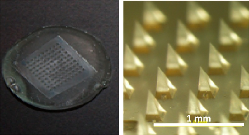
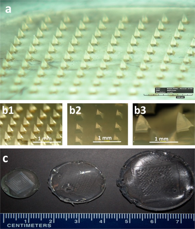
We first fabricated hydrogel microneedle patches based on micromolding methods described previously.16 Briefly, a blend of 15% poly(methyl vinyl ether-alt-maleic acid) (PMVE/MA) and 7.5% poly(ethylene glycol) (PEG) was cast onto a poly(dimethylsiloxane) (PDMS) microneedle mold and filled into the mold cavities under vacuum (see the Supporting Information). After drying, the patches were cured at 80 °C to cross-link the polymers. Cross-linking for 72 h produced patches that swelled approximately 3-fold with low variability after incubation in water for 24 h, whereas less-extensive cross-linking for 24 h produced less-desirable patches that swelled more than 50-fold with high variability (Figure 1 and Figure S1 in the Supporting Information).
Figure 1.

Swelling of microneedle patches made of cross-linked hydrogel. Microneedle patches were prepared by casting and drying an aqueous solution of poly(methyl vinyl-alt-maleic acid) and poly(ethylene glycol) into a micromold, after which the polymers were cross-linked by incubation at 80 °C (a). In the dry state, each microneedle measured 600 μm in height and 300 μm in width at the base (b1, c1). Upon incubation in water for 24 h, microneedles swelled to different sizes depending on the degree of hydrogel cross-linking during molding: cross-linking for 72 h (b2, c2) and 24 h (b3, c3).
To quantify the collection of a model analyte from microneedle patches, we used a double casting method to make the patches. We first cast a hydrogel solution containing the dye sulforhodamine B exclusively into the microneedle mold cavities and then cast the same hydrogel solution, but without the dye, onto the mold to form the patch base. To enable this process, we develop a new casting method involving a hydrophobic Teflon filter that facilitated selectively loading of the mold cavities (see the Supporting Information). This method produced patches with a controlled amount of dye (i.e., the model analyte) in the microneedles to simulate patches loaded with an analyte (Figure S2 in the Supporting Information).
A rigid backing was affixed to the microneedle patches to facilitate interfacing of the patches with analytical laboratory equipment. One method involved attaching a polystyrene disk to the microneedle patch using a double-sided adhesive disk. An alternative method, which avoids the need for an adhesive layer that can be a problematic source of moisture after drying, employed a polystyrene disk treated with plasma that was attached to the microneedle patch during molding while it was still wet (see the Supporting Information). After drying for 24 h at 80 °C, the patch and polystyrene backing were firmly attached without the need for adhesive (Figure S3 in the Supporting Information).
To demonstrate ISF extraction, microneedle patches were applied to the skin of rats in vivo and then removed after 1 h. As a negative control, microneedle patches were prepared with blunt-tipped microneedles that should not penetrate skin and were similarly applied to the skin. Application of a dye that stained sites of skin puncture after patch removal confirmed that the sharp-tipped microneedles penetrated the skin, whereas the blunt-tipped control patches did not (Figure S4 in the Supporting Information). All patches were weighed before and after application to the skin, which indicated that the microneedle patches extracted 0.84 ± 0.24 mg of ISF (average ± standard deviation, n = 7 replicates, see methods in the Supporting Information).
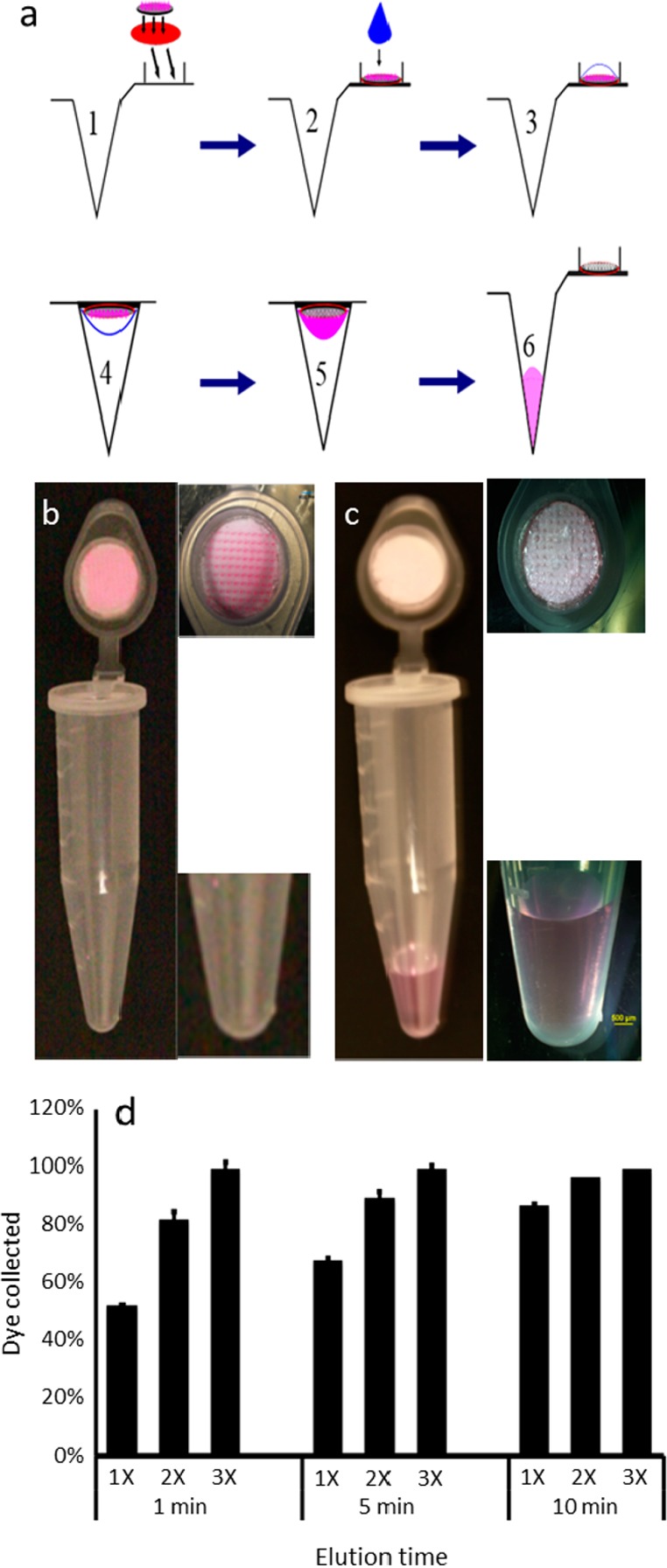
We next developed methods to collect analytes from microneedle patches by integrating them into conventional microtubes and microplates used in the analytical laboratory. The first method employed microneedle patches affixed within the cap of microcentrifuge tubes (Figure 2). The protocol involved dispensing 100 μL of water (or another buffer/solvent) onto the patch, incubating for up to 10 min to extract the model analyte (sulforhodamine), closing the cap and centrifuging for 20 s at 300g to collect the extracted analyte solution. In some cases this cycle was repeated once or twice. To assess the efficiency of this method, we varied the length of incubation time and the number of process cycles. Efficiency increased with both length of incubation time and number of cycles (Figure 2d, two-way ANOVA), where only 53% recovery of the model analyte was achieved after a single cycle with a 1 min incubation, but 100% recovery was achieved after three cycles independent of incubation time. Further optimization of the method is needed and will depend on the analyte being collected, especially if there is binding of the analyte to the microneedle matrix material.
Figure 2.

Collection of analytes from the microneedle patch by centrifugation: (a) A microneedle patch containing analytes of interest is adhered to the inner surface of a microcentrifuge tube cap (1). A drop of water is dispensed to the microneedles (2), allowed to extract/dissolve analytes from the microneedles (3), and the cap is closed (4). The analytes are then centrifuged to draw the analyte solution from the cap to the base of the microcentrifuge tube (5), which can then be removed from the bottom of the tube for subsequent analysis (6). This method is illustrated by showing a microneedle patch containing pink dye (sulforhodamine), which serves as a model analyte, before (b) and after (c) application of water and centrifugation. The results are quantified in part d, which shows the percentage of analyte collected from the microneedles into the elution fluid after application of 100 μL of water for 1, 5, or 10 min, and centrifugation at 300g, which was carried out one (1×), two (2×), or three (3×) times (n = 5 replicates ± standard deviation error bars).
For high-throughput analysis, we adapted the technique by using the microneedle patch with rigid backing to form a cap with a water-tight seal on top of the wells in a V-bottom multiwell microplate (Figure S5 in the Supporting Information). In this protocol, water was dispensed into each well of the plate, a microneedle patch was affixed to the top of each well using adhesive, the microplate was turned over and incubated for a period of time to extract the model analyte from the microneedles, the microplate was turned over again and briefly centrifuged to collect the extracted analyte, and finally the microneedle patches were removed so that the solution could be analyzed in situ in the microplate or removed for additional manipulation (e.g., further purification or concentration) and analysis.
We next developed methods for sample preparation in multiwell microplates without the need for centrifugation to separate extracted analytes from the microneedle patches. The simplest approach involved affixing microneedle patches to the bottom of each well in flat-bottom multiwell microplates using double-sided adhesive tape (Figure S6 in the Supporting Information). Water was dispensed into each well to extract the model analyte from the microneedles. Further sample preparation could be performed within the wells for subsequent analysis using a microplate reader or samples could be removed for analysis elsewhere. While this approach is simple, it has the drawback that an adhesive tape must be used, which could affect sample preparation and analysis.
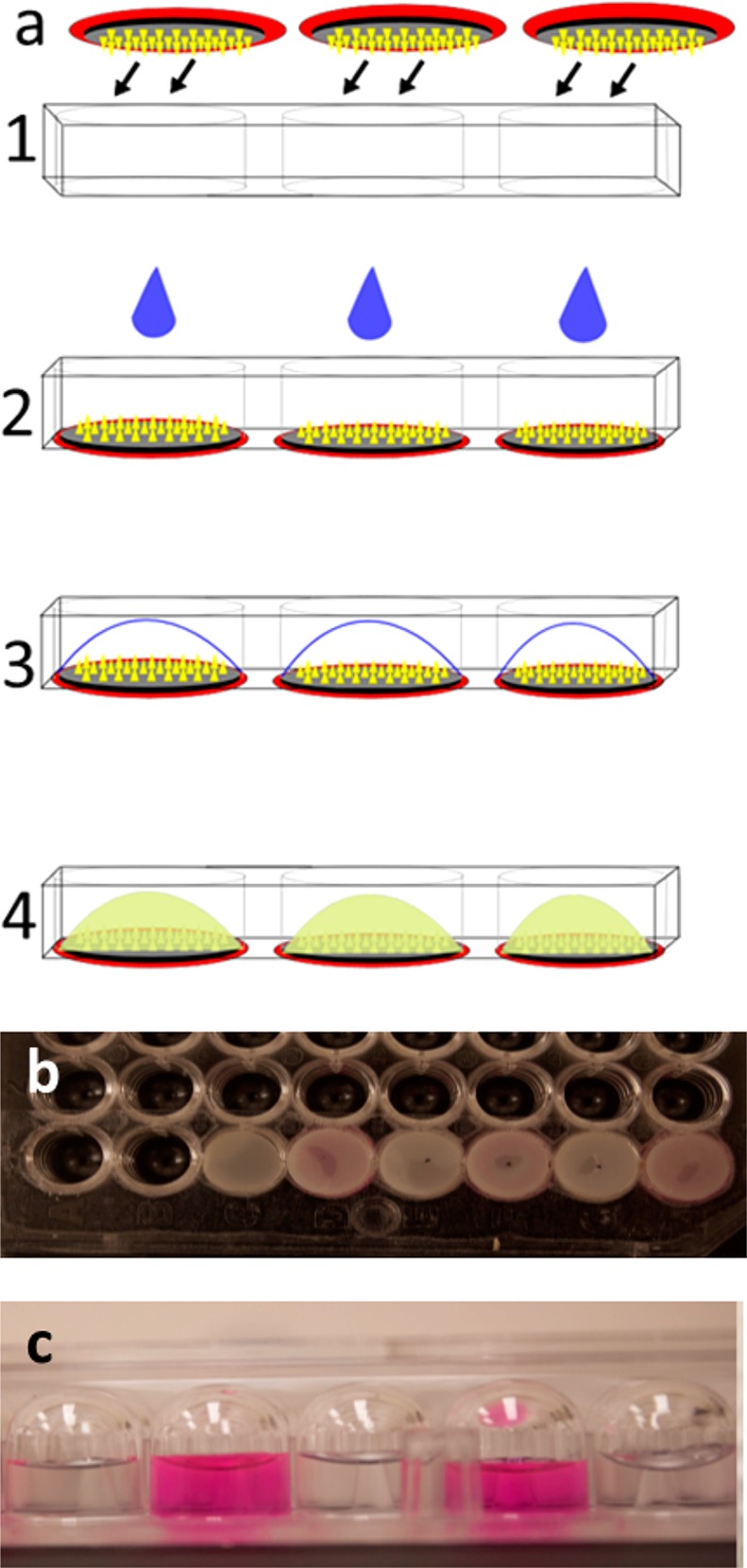
To address this limitation, we prepared bottomless multiwell microplates with double-sided adhesive film patterned to cover the surface of the microplate. While these devices were hand assembled, we expect that they could be mass produced at low cost by a commercial manufacturer. Microneedle patches with a rigid backing were then affixed on one side of the microplates, thereby creating a bottom to the microwells, to which water could be added to extract analytes from the microneedles (Figure 3). An alternate approach affixed microneedle patches to the open side of conventional flat-bottom multiwell microplates, thereby sealing the wells on all sides. In this case, water and/or any other reagents needed for analysis was added to the wells before affixing the microneedle patches.
Figure 3.

Collection of analytes by integration of microneedle patch into the multiwell microplate. (a) Microneedle patches with a hard backing are affixed to form the bottom of the wells of a bottomless multiwell microplate (1). A drop of water is dispensed to the microneedles (2, 3) to extract/dissolve analytes from the microneedles (4) to enable subsequent in situ analysis. (b) Microneedle patches adhered to the wells of a 96-well microplate. (c) View of dye solution (sulforhodamine) added to two wells and water added to neighboring wells, all sealed on the bottom with microneedle patches, demonstrating lack of material transfer between the wells after incubation for 12 h.
To demonstrate that these microwells were tightly sealed to avoid cross-contamination between wells, we filled alternating microwells sealed with microneedle patches with concentrated solutions of sulforhodamine and the other microwells with water. After incubation for 12 h, fluorescence in the microwells containing sulforhodamine solution was 2.3 × 10⁶ ± 0.2 × 10⁶, whereas fluorescence in the adjacent microwells containing water was at background levels of 13 ± 5 (expressed in arbitrary units, as measured by spectrofluorimetry) (Figure 3d), indicating no cross contamination between wells.
Altogether, these methods to collect analytes from microneedle patches can be a useful component to bring microneedle patch technology into use for screening, diagnosis, and monitoring in healthcare and environmental/workplace settings when used in combination with previous reports showing collection of analytes from the skin using microneedles.4−15 However, previous research has not addressed how analysis of microneedle patches could be integrated into the conventional analytical laboratory. The methods described here show that suitably designed microneedle patches can be incorporated into microtubes and microplates to collect analytes for subsequent analysis, thereby facilitating future automated and high-throughput assays.
After extraction of analytes from microneedles, we expect that further sample preparation and assays can be performed in situ within the microwells containing the microneedles. Alternatively, analyte solution can be removed from the microtubes or microwells for analysis using other instrumentation.
One of the motivations for developing microneedle patches to collect biomarkers from the skin is that its simplicity may allow use by minimally trained personnel in large screening campaigns or in developing countries where healthcare workers are in short supply.4−6 Microneedle patches might also be used directly by patients for monitoring of clinical biomarkers or workplace environmental exposures. By simplifying not only the biological sample acquisition through the use of microneedle patches, as demonstrated by others before,4−15 but also simplifying the analytical processing of the sample using methods shown here, microneedle patches may, with further development, increase the reach of screening, diagnosis, and monitoring of biomarkers to settings currently not well served.
Acknowledgments
This work was support in part by funding from the Ministry of Education of Perm Krai (Russia), Perm State University (Russia), and the National Institutes of Health (U.S.). We thank Donna Bondy for administrative support.
Supporting Information Available
This material is available free of charge via the Internet at http://pubs.acs.org.
The authors declare the following competing financial interest(s): Mark Prausnitz is an inventor of patents that have been licensed to companies developing microneedle-based products, is a paid advisor to companies developing microneedle-based products, and is a founder/shareholder of companies developing microneedle-based products. The resulting potential conflict of interest has been disclosed and is managed by Georgia Tech and Emory University.
Funding Statement
National Institutes of Health, United States
Supplementary Material
References
- Vaught J. B.; Henderson M. K. IARC Sci. Publ. 2011, 163, 23–42. [PubMed] [Google Scholar]
- Paliwal S.; Hwang B. H.; Tsai K. Y.; Mitragotri S. Eur. J. Pharm. Sci. 2013, 50, 546–556. [DOI] [PubMed] [Google Scholar]
- Wang C.Y.; Maibach H. I. Cutaneous Ocul. Toxicol. 2011, 30, 1–6. [DOI] [PubMed] [Google Scholar]
- Kim Y. C.; Park J. H.; Prausnitz M. R. Adv. Drug Delivery Rev. 2012, 64, 1547–1568. [DOI] [PMC free article] [PubMed] [Google Scholar]
- El-Laboudi A.; Oliver N. S.; Cass A.; Johnston D. Diabetes Technol. Ther. 2013, 15, 101–115. [DOI] [PubMed] [Google Scholar]
- Norman J. J.; Arya J. M.; McClain M. A.; Frew P. M.; Meltzer M. I.; Prausnitz M. R. Vaccine 2014, 32, 1856–1862. [DOI] [PMC free article] [PubMed] [Google Scholar]
- Li C. G.; Lee C. Y.; Lee K.; Jung H. Biomed. Microdevices 2013, 15, 17–25. [DOI] [PubMed] [Google Scholar]
- Miller P. R.; Xiao X.; Brener I.; Burckel D. B.; Narayan R.; Polsky R. Adv. Healthcare Mater. 2014, 3, 876–881. [DOI] [PubMed] [Google Scholar]
- Jina A.; Tierney M. J.; Tamada J. A.; McGill S.; Desai S.; Chua B.; Chang A.; Christiansen M. J. Diabetes Sci. Technol. 2014, 8, 483–487. [DOI] [PMC free article] [PubMed] [Google Scholar]
- Windmiller J. R.; Zhou N.; Chuang M. C.; Valdés-Ramírez G.; Santhosh P.; Miller P. R.; Narayan R.; Wang J. Analyst 2011, 136, 1846–1851. [DOI] [PubMed] [Google Scholar]
- Invernale M. A.; Tang B. C.; York R. L.; Le L.; Hou D. Y.; Anderson D. G. Adv. Healthcare Mater. 2014, 3, 338–342. [DOI] [PubMed] [Google Scholar]
- Wang P. M.; Cornwell M.; Prausnitz M. R. Diabetes Technol. Ther. 2005, 7, 131–141. [DOI] [PubMed] [Google Scholar]
- Muller D. A.; Corrie S. R.; Coffey J.; Young P. R.; Kendall M. A. Anal. Chem. 2012, 84, 3262–3268. [DOI] [PubMed] [Google Scholar]
- Donnelly R. F.; Mooney K.; Caffarel-Salvador E.; Torrisi B. M.; Eltayib E.; McElnay J. C. Ther. Drug Monit. 2014, 36, 10–17. [DOI] [PubMed] [Google Scholar]
- Sakaguchi K.; Hirota Y.; Hashimoto N.; Ogawa W.; Sato T.; Okada S.; Hagino K.; Asakura Y.; Kikkawa Y.; Kojima J.; Maekawa Y.; Nakajima H. Diabetes Technol. Ther. 2012, 14, 485–491. [DOI] [PubMed] [Google Scholar]
- Lee J. W.; Park J. H.; Prausnitz M. R. Biomaterials 2008, 29, 2113–2124. [DOI] [PMC free article] [PubMed] [Google Scholar]
Associated Data
This section collects any data citations, data availability statements, or supplementary materials included in this article.


