Abstract
Purpose
To develop a high temporal resolution MR imaging technique that could be employed with magnetically-assisted remote control (MARC) endovascular catheters.
Materials and Methods
A technique is proposed based on selective intra-arterial injections of dilute MR contrast at the beginning of a fluoroscopic MR angiography acquisition. The initial bolus of contrast is used to establish a vascular roadmap upon which MARC catheters can be tracked. The contrast to noise ratio of the achieved roadmap was assessed in phantoms and in a swine animal model. The ability of the technique to permit navigation of activated MARC catheters through arterial branch points was evaluated.
Results
The roadmapping mode proved effective in phantoms for tracking objects and achieved a contrast to noise ratio of 35.7 between the intra and extra-vascular space. In vivo, the intra-arterial enhancement strategy produced roadmaps with a contrast to noise ratio of 42.0. The artifact produced by MARC catheter activation provided signal enhancement patterns on the roadmap that experienced interventionalists could track through vascular structures.
Conclusion
A roadmapping approach with intra-arterial CE-MRA is introduced for navigating the MARC catheter. The technique mitigates the artifact produced by the MARC catheter, greatly limits the required SAR, permits regular roadmap updates due to the low contrast agent requirements, and proved effective in the in vivo setting.
Keywords: Magnetic resonance angiography, digital subtraction angiography, endovascular procedure, interventional MR
Introduction
Magnetic Resonance (MR) guidance of endovascular procedures offers potential benefits that include the ability to visualize both the vascular lumen and surrounding soft tissue without the use of ionizing radiation 1-2. MR techniques permit both anatomic delineation and physiologic assessments. The MR environment further provides an opportunity to remotely induce catheter deflections by integrating microcoils into the tips of catheters 3-4. These devices are called magnetically-assisted remote control (MARC) endovascular catheters and they transiently apply DC current to the microcoil to create a small magnetic field at the catheter tip. This induced magnetic field produces forces that tend to bring the induced magnetic field vector into alignment with the large static magnetic field of an MR scanner (B0). Thus, deflection of the MARC catheter tip occurs when the magnetic field generated by the microcoil is not parallel to B0. The resulting deflection can assist when steering into or through challenging vascular structures 5. An unfortunate side effect of MARC catheters, however, is the production of a local disturbance in the static magnetic field of the MR scanner when they are activated. This disturbance of B0 spoils the signal near the catheter tip at precisely the time that catheter and vascular visualization is most critical. The spatial extent of the signal disturbance scales with the current in the MARC catheter and numerous imaging related parameters, but is commonly more than a centimeter in diameter. Thus, overcoming the artifact generated by MARC catheter activation is a critical requirement for this promising technology.
In this study we aimed to develop a high temporal resolution MR imaging technique that could be employed with MARC endovascular catheters. The approach leverages the fact that a catheter is present within the vascular system. Thus, real time intra-arterial MR angiography 6-9 (MRA) can be performed and updated transiently throughout the procedure. This, in combination with digital subtraction angiography (DSA) methods borrowed for X-ray imaging approaches, permits the creation of “roadmaps” that can robustly delineate vascular structures during MARC catheter activation.
Materials and Methods
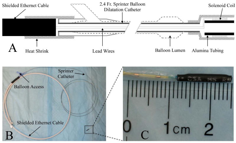
All MR imaging was performed on a 1.5T clinical unit (Philips Achieva, Cleveland, OH) and external receive-only surface coil arrays were employed for signal reception. The MARC catheter (Fig 1) was constructed on a 2.4 French (Fr) diameter Sprinter (Medtronic, Minneapolis, MN) over-the-wire balloon dilation catheter. Copper magnet wire (California Fine Wire, Grover Beach, CA) measuring 0.002 inches in diameter was used to wind a solenoidal microcoil at the distal tip of the catheter. The solenoid coil consisted of 30 turns of copper wire wrapped around a 1.25 mm outer diameter alumina tube that was 9.4 mm in length. The tip was covered with heat shrink tubing (Component Force LLC, St. Louis, MO) resulting in a final distal tip outer diameter of 6 Fr. The magnet wire length was sufficiently long to run through the 138cm inner lumen of the catheter and back again. The proximal leads of the MARC catheter were connected to a current source (Lambda Electronics, Model LPD-422A-FM), which was located outside the magnet room, via a 10m long fully screened twisted pair ethernet cable. The catheter was introduced into phantoms and animal models via an 8Fr introducer sheath.
Figure 1.

The MARC catheter construction is summarized. The schematic overview (A) indicates the presence of intra-luminal lead wires that connect the distal solenoidal coil on the catheter tip to the proximal ethernet cable at the catheter hub. The latter is subsequently connected to a current source for coil activation. The relative position of the balloon to the tip mounted coil can also be appreciated. The physical device (B) is shown, with a zoomed in view of the tip (C) assembly on the Sprinter catheter.
Roadmapping Mode
The technique developed for MR imaging during MARC catheter activation is based on selective intra-arterial (IA) injections of dilute gadolinium (Gd) contrast medium (Magnevist, Bayer HealthCare) at the beginning of a fluoroscopic MRA acquisition. The MRA protocol was a thick slice 2 dimensional (2D) gradient echo sequence (FOV=260mm×240mm, slice=10mm, matrix=256×256, TR/TE/flip=8ms/2ms/20°, bandwidth=192 Hz/pixel, acquisition time=1.3s, specific absorption rate (SAR)=0.2W/kg). A complete MRA image was acquired at the beginning of an imaging “run”, in which the same image is continuously acquired and displayed in a fluoroscopic mode. After acquiring the first image in 1.3s, keyhole methods 10 are employed to increase the temporal resolution of the remaining imaging run. With this approach, only the central portion of k-space is continuously acquired and the remaining portion of the data is filled in with “old” data that was obtained in the first MRA image. In this application a keyhole percentage of 40% was employed, which reduced the image acquisition time to 0.5 seconds (2.0 frames/second) during catheter navigation. The roadmap is generated by subtracting the first acquired image from all future images in a run, in a manner analogous to DSA.
Arterial enhancement was generated by IA contrast enhanced MRA methods. Stock Magnevist (0.5M) MR contrast was diluted in physiological saline to 10mM (2% of original strength) for all studies. This was necessitated by the fact that the contrast agent immediately enters the vessel to be imaged and does not experience the natural dilution associated with remote systemic intravenous administration. Vascular enhancement was obtained by injecting a 4s long bolus of 10 mM MR contrast at a rate appropriate for the vessel of interest (2 ml/s for the distal aorta). The imaging run begins 2s after injection initiation to allow for distribution of the injectate and to assure that enhancement is maintained throughout the initial image in the run. This initial contrast enhanced MRA is the reference “mask” that is subtracted from subsequent images in the run. The contrast agent was rapidly washed out with blood flow and subtraction of the initial image from later images revealed the vascular structures that were initially enhanced. The low Gd concentration and short bolus IA injection permits exceptionally low contrast doses. For example, if 8ml of 10mM Gd are injected over 4s into the abdominal aorta, then this is equivalent to only 0.16ml of full strength Magnevist having been delivered (8ml × 2%). This makes it practical to regularly update the roadmap whenever conditions so indicate or when a different view is required.
Phantom Experiments
The technique was tested in a flow phantom that mimicked the spatial characteristics of the distal aorta. A thin rubber mold that contained simulated renal branches and an iliac bifurcation was used to isolate intravascular and extravascular spaces. The vascular lumen was initially filled with water and connected to a simple gravity driven flow system. The extravascular space was static and filled with water. The MARC catheter was introduced into the vascular lumen and an imaging run was created as described above. In order to demonstrate the ability to track objects in the absence of MARC catheter activation, the balloon of the Sprinter catheter was inflated with 5mM Gd solution and tracked through an imaging run. The contrast to noise (CNR) ratio of the roadmap was determined by measuring the signal difference in regions of interest (ROI) in the intravascular and extravascular spaces after the roadmap had fully formed and dividing this value by the standard deviation of the signal in a region or air.
Animal Experiments
The roadmapping technique was further tested in swine (30-32 kg farm pigs). Experimental pigs received humane care and the experimental protocol was approved by the University’s Institutional Animal Care and Use Committee. Anesthesia was performed as previously described 11 and an 8Fr sheath was inserted into the carotid artery percutaneously. Heparin (100 IU/kg) was administered intravenously and the MARC catheter was advanced into the descending aorta. An imaging run was created as described above with a FOV that was centered on the abdominal aorta and iliac bifurcation. Once the roadmap was established the achieved CNR was measured as outlined above. Since the background signal is variable, a homogenous ROI adjacent to the aorta was selected for contrast comparisons. The MARC catheter was activated at a current level of 300mA and navigated into the left and right iliac arteries under real time MR guidance. The spatial extent of the artifact generated by the MARC catheter was assessed by measuring the dimensions of the area of signal void it produced when activated. Since the shape of the artifact will vary depending on the devices orientation with respect to the main magnetic field, the measurements were taken along the largest dimension of the artifact and perpendicular to this measure. The ability to track the MARC catheter at lower current levels was explored by sequentially reducing current in the catheter to 100mA, 50mA and finally 10 mA. In each case the device was advanced into both iliac arteries under MR guidance.
Results
Phantom Experiments
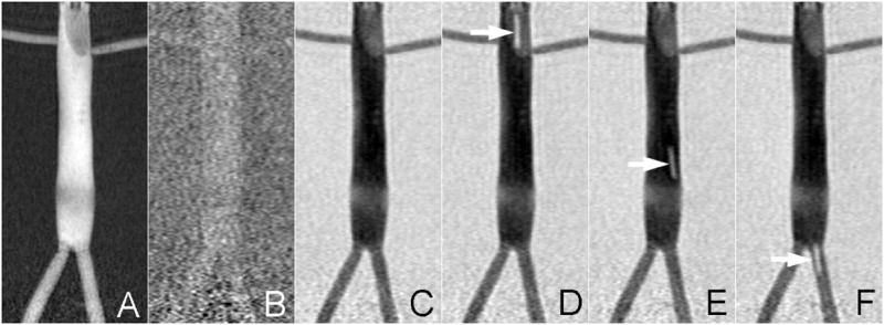
Figure 2 demonstrates the roadmapping mode on a vascular phantom that mimics the distal aorta. The described angiographic imaging protocol was initially acquired in 1.3s while 10mM Gd-based MR contrast was injected at 2ml/s. Subtraction of all subsequent frames began immediately (Fig 2B) and the roadmap was not established until the contrast infusion was flushed out of the vascular space (Fig 2C). Once established, the roadmap was static provided the phantom was stationary within the bore and no catheter manipulations were performed. The achieved CNR between the intra- and extra-luminal space of the phantom was 35.7 once the roadmap was established. Inflation of the balloon with a 5mM Gd solution permitted the interventionalist (SWH, MWW, FS) to localize the catheter tip against the established roadmap and allowed the catheter to be tracked through the vascular phantom (Fig 2D-F). The MARC catheter was not activated during this exercise to demonstrate the ability of the technique to also track objects with positive contrast.
Figure 2.

The roadmapping mode is demonstrated on a vascular phantom that mimics the distal aorta. IA contrast is administered at the start of the run to highlight the vasculature (A). This reference is subtracted from all subsequent scans and thus initially there is minimal contrast (B). The roadmap only appears once the contrast injection is washed out (C) and is durable for the remainder of the run. It is possible to track bright objects against this roadmap as demonstrated by inflating the balloon catheter with 1mM Gd (arrows in D-F).
Animal Experiments
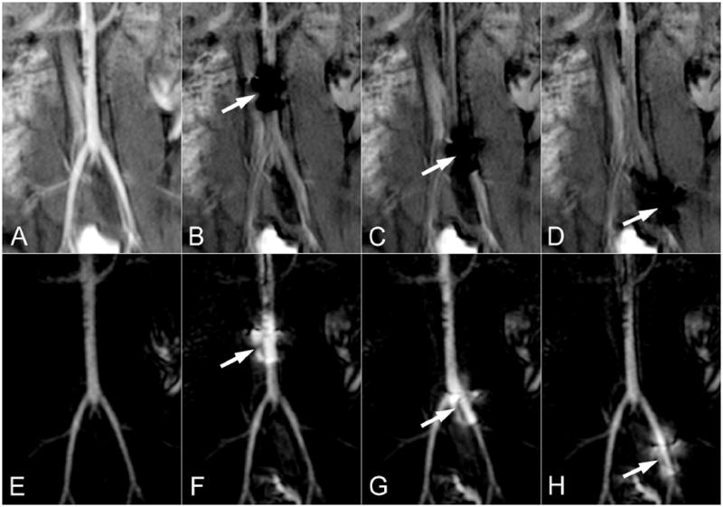
The MARC catheter was successfully introduced into the aorta via a carotid sheath. IA MRA was initially used to position a scan plane such that it was centered at the aortic bifurcation. A fluoroscopic imaging run was then begun during IA contrast infusion (Fig 3A) and a roadmap was established (Fig 3E) once blood flow had cleared this initial injection. The achieved CNR between the vascular lumen and adjacent tissue was 42.0 once the roadmap (Fig 3E) was established. Note that extravascular tissue exhibits moderate signal intensity (Fig 3A) that is comparable to the intravascular signal intensity following wash-out of the contrast (Fig 3B). Activation of the MARC catheter produced a substantial multilobed artifact that spoils signal in a region measuring up to 18mm × 28mm (Fig 3B). The signal spoiled region on the source images creates a local signal enhancement on the roadmap (Fig 3F), since the spoiled region has a greater signal intensity difference between the contrast enhanced baseline and later real time images. The enhanced region encompasses both the vessel and surrounding tissue since the protocol was designed to have similar signal intensities from both these regions. This enhancement is superimposed on the vascular architecture, which retains its general appearance. The artifact created by the MARC catheter can then be used to track the device through the established vascular roadmap (Fig 3 F-H).
Figure 3.

The roadmapping approach is demonstrated in the distal aorta of a swine. The source images are shown on the top row and the roadmapping mode images are on the bottom row. An IA injection of Gd is initially used to highlight arterial anatomy (A) and establish the roadmap (E). The MARC catheter is then activated, producing a substantial signal void on the source images (arrows in B-D) and a signal enhancement pattern on the roadmap images that is superimposed on the arterial anatomy (arrows in F-H). The roadmap images can be used to track the device without losing visibility of the local arterial anatomy.
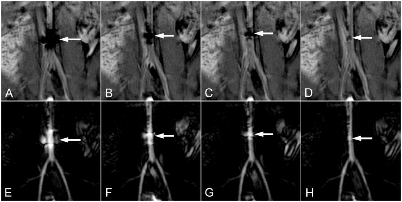
The applied current of 300mA is typical of what may be employed to achieve a strong deflection of the catheter tip 12. In this case, orientation of the MARC catheter solenoid and B0 were approximately co-linear and minimal deflection was produced at all current levels. The artifact produced by MARC catheter activation scaled with applied current and was trackable by experienced interventionalists (SWH, MWW, FS) even at very low current levels (Fig 4A-D). Iterative updating of IA MRA roadmaps was necessary when tracking MARC catheters over long distances and tortuous vessels. This proved to be practical due to the short duration of the IA MRA sequence and the very low contrast dose that was required to establish an updated roadmap.
Figure 4.

The effect of several MARC catheter current levels are demonstrated on the source (top row) and roadmapping (bottom row) images. Current levels of 300mA (A,E), 100mA (B,F), 50mA (C,G) and 10mA (D,H) are demonstrated in the distal aorta of a swine. The spatial extent of the artifact on the source images (top row arrows) scales with current and is still evident at very low current levels. The corresponding signal increase on the roadmap images (bottom row arrows) similarly localizes the catheter tip even at very low current levels.
Discussion
The major finding of this study was that IA MRA roadmapping is a simple, low SAR approach for tracking MARC catheters that allows for high temporal resolution and requires only minimal Gd dose. The display is similar to that employed in radiographic DSA, which may improve acceptance in the clinical setting. Advantages of the roapmapping approach include the fact that local arterial anatomy is established at the outset and is retained throughout the fluoroscopic acquisition period. The MRA sequence is only moderately T1-weigthed to assure that tissue will have modest signal intensity on the source images. The localized signal loss on these source images during MARC catheter activation creates an enhancement pattern on the roadmaps that was effectively used to visualize and track the catheter tip. The source images also reveal the spatial position of the catheter tip, but the local arterial anatomy is obscured when the current is on. Substantial vascular enhancement was demonstrated with small volume injections of low concentration MR contrast due to the localized intra-arterial administration. This permits regular roadmap updating whenever the desired view changes or patient motion occurs.
The technique builds on prior studies that have utilized passive visualization of catheters and intra-arterial MR angiography. Passive tracking approaches rely on catheters with embedded components that produce a modest artifact level that is sufficient for visualization, but will not substantially obscure surrounding structures 13. In contrast, the MARC catheter is capable of creating substantially greater artifact and requires a technique that is resilient to MARC catheter activation. Prior intra-arterial MR angiography methods have not emphasized roadmap creation, instead focusing on the benefits of being able to temporally track the contrast injection 6-9. The proposed technique therefore differs in that it establishes a static vascular roadmap against which endovascular devices can be tracked. It sacrifices the ability to track the injected contrast for the ability to retain arterial visualization in the presence MARC catheter activation. Moreover, the technique is inherently very low SAR, which is particularly relevant to MARC catheters as they contain long conductive elements that may experience heating during radio-frequency (RF) excitation 14-15. This is in contradistinction to MR sequences that are commonly applied for intra-arterial MRA 7-9 or fluoroscopic purposes 2, which utilize steady state approaches and require short repetition times and relatively large flip angles 16. These steady state sequences are also particularly sensitive to magnetic field disturbances, such as those created by MARC catheter activation. Thus, conventional approaches to intra-arterial MRA and real time MR imaging are particularly ill-suited to the MARC catheter.
In this proof of principle study a MARC catheter with a solenoidal winding at its tip was used. Accordingly, the catheter did not experience strong deflections during activation due to the fact that the aorta was oriented largely along the B0 axis. Strong deflections in this vessel orientation would require a saddle shaped coil winding 12. The purpose of this study, however, was to demonstrate the ability to track the device even when the MARC catheter was generating artifact. Functional deflections of the MARC catheter were not necessary to achieve this goal. Notably, low level MARC catheter activation (10-50 mA) permitted catheter tracking and would produce minimal deflection even if the MARC catheter was not collinear with B0. These low current levels could therefore be employed for navigating the catheter when catheter deflection is not necessary.
The limitations of the technique relate largely to its single plane subtraction based approach. The single scan plane must be appropriately positioned to be effective and through plane motion cannot be appreciated. A global baseline 3D angiographic sequence is extremely helpful for planning the spatial positioning of the roadmap scans. The 2D nature of these planes, however, does limit the anatomic view of the vessels that can be achieved. A roadmap orientation that visualizes the relevant vascular structure in plane is critical to effective navigation. This is analogous to x-ray angio methods, where and appropriate projection view is necessary for efficient navigation. Improved MR navigation could be achieved via iterative orthogonal views or 3D approaches, but would suffer temporal resolution penalties. Since the roadmap is designed to reveal vascular structures it is also possible that changes in surrounding soft tissue will not be appreciated. Parallel displays showing both the source and subtracted roadmap images could help alleviate this concern.
In conclusion, a DSA based roadmapping approach with intra-arterial contrast enhanced MRA is proposed for guiding endovascular procedures that utilize the MARC catheter. The technique addressed both the artifact produced by the MARC catheter and greatly limits the required SAR. The roadmaps can be regularly updated due to the low contrast requirements and proved effective for tracking MARC catheters in the in vivo setting.
Acknowledgments
Grant support from the NIH National Institute of Biomedical Imaging and Bioengineering (NIBIB) Award (S. Hetts): 1R01EB012031
Abbreviation Key
- B0
static magnetic field of an MR scanner
- CNR
contrast to noise ratio
- DSA
digital subtraction angiography
- FOV
field of view
- fps
frames per second
- Gd
Gadolinium based MR contrast agent
- IA
intra-arterial
- MARC
magnetically-assisted remote control
- MR
magnetic resonance
- MRA
magnetic resonance angiography
- RF
radio-frequency
- ROI
region of interest
- SAR
specific absorption rate
References
- 1.Bock M, Wacker FK. MR-guided intravascular interventions: techniques and applications. J Magn Reson Imaging. 2008 Feb;27(2):326–338. doi: 10.1002/jmri.21271. [DOI] [PubMed] [Google Scholar]
- 2.Saeed M, Hetts SW, English J, Wilson M. MR fluoroscopy in vascular and cardiac interventions (review) Int J Cardiovasc Imagingn. 2012 Jan;28(1):117–137. doi: 10.1007/s10554-010-9774-1. [DOI] [PMC free article] [PubMed] [Google Scholar]
- 3.Roberts TP, Hassenzahl WV, Hetts SW, Arenson RL. Remote control of catheter tip deflection: an opportunity for interventional MRI. Magn Reson Med. 2002 Dec;48(6):1091–1095. doi: 10.1002/mrm.10325. [DOI] [PubMed] [Google Scholar]
- 4.Settecase F, Sussman MS, Wilson MW, et al. Magnetically-assisted remote control (MARC) steering of endovascular catheters for interventional MRI: a model for deflection and design implications. Med Phys. 2007 Aug;34(8):3135–3142. doi: 10.1118/1.2750963. [DOI] [PMC free article] [PubMed] [Google Scholar]
- 5.Hetts SW, Saeed M, Martin A, et al. Magnetically-Assisted Remote Controlled Microcatheter Tip Deflection under Magnetic Resonance Imaging. J Vis Exp. 2013;(74) doi: 10.3791/50299. [DOI] [PMC free article] [PubMed] [Google Scholar]
- 6.Bos C, Smits HF, Bakker CJ, Viergever MA. Selective contrast-enhanced MR angiography. Magn Reson Med. 2000 Oct;44(4):575–582. doi: 10.1002/1522-2594(200010)44:4<575::aid-mrm11>3.0.co;2-s. [DOI] [PubMed] [Google Scholar]
- 7.Green JD, Omary RA, Finn JP, et al. Two- and three-dimensional MR coronary angiography with intraarterial injections of contrast agent in dogs: a feasibility study. Radiology. 2003 Jan;26(1):272–277. doi: 10.1148/radiol.2261011848. [DOI] [PubMed] [Google Scholar]
- 8.Guttman MA, Raval AN, Lederman RJ, McVeigh ER. Real-time catheter-directed MRA with effective background suppression and persistent rendering. J Magn Reson Imaging. 2008 Aug;28(2):538–542. doi: 10.1002/jmri.21409. [DOI] [PMC free article] [PubMed] [Google Scholar]
- 9.Green JD, Omary RA, Schirf BE, Tang R, Li D. Catheter-directed contrast-enhanced coronary MR angiography in swine using magnetization-prepared True-FISP. Magn Reson Med. 2003 Dec;50(6):1317–1321. doi: 10.1002/mrm.10642. [DOI] [PubMed] [Google Scholar]
- 10.van Vaals JJ, Brummer ME, Dixon WT, et al. “Keyhole” method for accelerating imaging of contrast agent uptake. J Magn Reson Imaging. 1993 Jul-Aug;3(4):671–675. doi: 10.1002/jmri.1880030419. [DOI] [PubMed] [Google Scholar]
- 11.Bernhardt A, Wilson MW, Settecase F, et al. Steerable catheter microcoils for interventional MRI reducing resistive heating. Acad Radiol. 2011 Mar;18(3):270–276. doi: 10.1016/j.acra.2010.09.010. [DOI] [PMC free article] [PubMed] [Google Scholar]
- 12.Wilson MW, Martin AB, Lillaney P, et al. Magnetic catheter manipulation in the interventional MR imaging environment. J Vasc Interv Radiol. 2013 Jun;24(6):885–891. doi: 10.1016/j.jvir.2013.01.487. [DOI] [PMC free article] [PubMed] [Google Scholar]
- 13.Bakker CJ, Bos C, Weinmann HJ. Passive tracking of catheters and guidewires by contrast-enhanced MR fluoroscopy. Magn Reson Med. 2001 Jan;45(1):17–23. doi: 10.1002/1522-2594(200101)45:1<17::aid-mrm1003>3.0.co;2-9. [DOI] [PubMed] [Google Scholar]
- 14.Martin AJ, Baek B, Acevedo-Bolton G, Higashida RT, Comstock J, Saloner DA. MR imaging during endovascular procedures: an evaluation of the potential for catheter heating. Magn Reson Med. 2009 Jan;61(1):45–53. doi: 10.1002/mrm.21817. [DOI] [PubMed] [Google Scholar]
- 15.Settecase F, Hetts SW, Martin AJ, et al. RF Heating of MRI-Assisted Catheter Steering Coils for Interventional MRI. Acad Radiol. 2011 Mar;18(3):277–285. doi: 10.1016/j.acra.2010.09.012. [DOI] [PMC free article] [PubMed] [Google Scholar]
- 16.Elgort DR, Duerk JL. A review of technical advances in interventional magnetic resonance imaging. Acad Radiol. 2005 Sep;12(9):1089–1099. doi: 10.1016/j.acra.2005.06.003. [DOI] [PubMed] [Google Scholar]


