

Abstract
Experimental challenges associated with characterization of the membrane-bound form of talin have prevented us from understanding the molecular mechanism of its membrane-dependent integrin activation. Here, utilizing what we believe to be a novel membrane mimetic model, we present a reproducible model of membrane-bound talin observed across multiple independent simulations. We characterize both local and global membrane-induced structural transitions that successfully reconcile discrepancies between biochemical and structural studies and provide insight into how talin might modulate integrin function. Membrane binding of talin, captured in unbiased simulations, proceeds through three distinct steps: initial electrostatic recruitment of the F2 subdomain to anionic lipids via several basic residues; insertion of an initially buried, conserved hydrophobic anchor into the membrane; and association of the F3 subdomain with the membrane surface through a large, interdomain conformational change. These latter two steps, to our knowledge, have not been observed or described previously. Electrostatic analysis shows talin F2F3 to be highly polarized, with a highly positive underside, which we attribute to the initial electrostatic recruitment, and a negative top face, which can help orient the protein optimally with respect to the membrane, thereby reducing the number of unproductive membrane collision events.
Introduction
Talin is an abundant and ubiquitous cytoskeletal-associated protein, which was shown to be essential to cell-extracellular matrix adhesion at hemidesmosomes and focal adhesions more than three decades ago (1). Talin is now known to be the final common protein in all signaling pathways that lead to integrin activation (2,3) and plays a prominent regulatory role in integrin-mediated cell adhesion processes (4). Integrins are heterodimeric cell-surface receptors that are crucial for signal transduction in cell differentiation, platelet coagulation, leukocyte recruitment, and tumor metastasis (5–9). They are composed of one α- and one β-subunit, with each subunit consisting of a short cytoplasmic tail, a single transmembrane helix, and a large extracellular domain (10,11). The mammalian genome encodes for 18 distinct α-subunits and eight distinct β-subunits, which are assembled into 24 distinct integrin dimers, each with a unique function (5). Most integrins are expressed in a default, low ligand-affinity state termed the “off-state”. Integrin conformation must be altered to generate a high ligand-affinity state that transmits signals across the cell membrane (2,3,5,6,8–14). This process is known as “integrin activation” and occurs at the membrane surface in response to both cytoplasmic and extracellular signals, respectively termed “inside-out” and “outside-in” signaling (5). Recent studies have identified talin, a cytoskeletal-associated protein, as the most potent inside-out activator of integrins (2,3,9,12–14).
Talin is a high-molecular-weight peripheral membrane protein (270 kDa) composed of a large rod domain (see Fig. S1 in the Supporting Material), which interacts with the cytoskeleton, and a smaller head domain, which binds to the membrane surface and activates integrin (4,13,14). The talin head domain consists of four subdomains, namely the F0, F1, F2, and F3 subdomains (15–17). The F2 and F3 subdomains are key to the membrane binding process as well as to the activation of integrin at the membrane surface (18,19). Although the F3 subdomain is sufficient for integrin activation (20), interactions between talin’s positively charged membrane orientation patch (MOP) in the F2 subdomain (see Fig. S1, b and c) and anionic lipids, such as phosphatidylserine (PS) (21) and PIP2 (22,23), greatly enhance the rate of integrin binding and activation (24). Therefore, a proper description of the membrane-bound talin F2F3 subdomain is necessary to fully understand the mechanism of inside-out integrin activation.
Structures of talin in solution (i.e., in the absence of membrane) have been solved (21,25–27); however, discrepancies between biochemical data and structural models remain. While biochemical and structural studies (21,23,26,28) have both shown the basic residues in the talin MOP to be essential for membrane binding, several other membrane binding moieties known to exist, such as an F3 association patch (FAP) or hydrophobic membrane anchor (23,27,29–32), have not been described by structural models to date. For example, mutation of certain basic residues in the F3 subdomain have been shown to diminish integrin activation (23,32). Because these residues are not thought to interact with integrin, it has been suggested that the F3 subdomain must interact with the membrane to properly bind both the membrane-proximal and membrane-distal interaction sites on integrin (27,33). The relative orientation of the F2 and F3 subdomains in crystal structures, however, precludes the simultaneous binding of the basic faces of the F2 and F3 subdomains with the membrane. Because the F3 subdomain is the primary link between talin and integrin, knowing the position of the F3 subdomain relative to the membrane is also a crucial point in understanding talin-dependent activation of integrin.
Although it has been shown by thin film studies (29), antibody labeling (30), and construction and computational analysis of synthetic peptides (34,35) that talin inserts into the hydrophobic core of the membrane, the hydrophobic binding moiety has not been identified in either biochemical or structural studies to date. In 2010, coarse-grained molecular dynamics (MD) simulations (28) have been utilized to address membrane binding of talin. Although these simulations verified the role of MOP residues in membrane association of talin, they did not characterize a hydrophobic membrane anchor, nor direct interaction of the F3 subdomain with the membrane due to the restrictions imposed on protein structure inherent to coarse-grained MD. To understand how talin affects the dynamics of integrin and ultimately activates it, one must understand how the membrane might drive the structural changes in talin that lead to proper interaction with integrin.
Here, we utilize all-atom MD simulations to address several questions surrounding the membrane binding of talin and how membrane binding modulates the structural and dynamical properties of talin to optimally interact with and activate integrin. With the aid of our recently developed membrane mimetic model (36), five independent simulations of the talin F2F3 subdomain binding to a PS bilayer were performed. Across these simulations, the talin F2F3 subdomain spontaneously bound to the membrane, providing a well-equilibrated model of the membrane-bound form of talin. The importance of the basic MOP residues in attracting talin to the anionic surface of the membrane is apparent in all simulations. We also have identified a previously uncharacterized Phe-rich membrane anchor in the F2 subdomain, which firmly anchors talin to the membrane surface. The membrane anchor of talin has not been described in either x-ray diffraction or NMR studies (21,25,26) due to its deep burial inside the protein while in solution, the anchor only being exposed upon membrane binding. After the association of the F2 subdomain with the membrane, we observe a large, membrane-induced conformational change between the F2 and F3 subdomains that brings the F3 subdomain into direct contact with the membrane and can account for the structural change that positions talin to optimally interact with integrin. These results have revealed the role of the membrane as an active platform for properly positioning talin for inside-out integrin activation.
Methods
Modeling the talin F2F3 subdomain
The initial structure of the talin F2F3 subdomain (consisting of residues 192–408) was taken from the crystal structure of a talin F2F3/integrin β1D complex (PDB:3G9W) (21), deposited in the RCSB Protein Data Bank (Research Collaboratory for Structural Bioinformatics; http://home.rcsb.org/). Hydrogen atoms, a C-terminal carboxylate capping group, and an N-terminal ammonium capping group were added using the PSFGEN plugin of the software VMD (University of Illinois at Urbana-Champaign, Champaign, IL; http://www.ks.uiuc.edu/research/vmd/) (37). Structural water molecules were retained, whereas artifacts from the crystallization medium (i.e., glycerol and di(hydroxyethyl)ether) were removed before the simulations. The protein was then solvated in 22,518 water molecules and ionized with 61 Na+ ions and 67 Cl− ions (150 mM NaCl) using the SOLVATE and AUTOIONIZE plugins of VMD to give the system final dimensions of 88 × 93 × 93 Å3 containing ∼71,500 atoms. The system was energy-minimized and equilibrated as an NPT ensemble (P = 1.0 atm, T = 310 K) for 2 ns without constraints. The resulting structure was used as the initial structure for all subsequent membrane-binding simulations. The simulation of the equilibrated system in solution was extended to 40 ns under the same conditions to describe the behavior of talin in solution and provide a control system to compare with the membrane-binding simulations.
Membrane simulations of talin F2F3 subdomain
Capturing the membrane binding of peripheral proteins using all-atom simulations employing full-length lipids has proven to be prohibitively costly, preventing multiple, independent runs and the collection of sufficient statistics. To circumvent this problem, multiple methods have been employed to study membrane binding of peripheral proteins with increasing levels of approximation, including coarse-grained models (28,38–41) and implicit membrane models (42–44). However, these models lack the atomic detail necessary for accurate description of specific protein-lipid interactions. With the aid of a novel membrane mimetic recently developed in our laboratory (36), we were able to perform multiple independent simulations (n = 5) of talin F2F3 spontaneously binding to the membrane. The highly mobile membrane mimetic model (HMMM) is created by placing short-tailed lipids, such as DBPS (1,2-dibutyl-sn-3-glycero-phosphatidylserine), at the interface of an aqueous-organic biphasic system. This greatly expedites the dynamics of the lipid headgroups, allowing for rapid and spontaneous insertion of peripheral proteins (36) without compromising the atomic details of the headgroups that are often key for proper description of specific lipid-protein interactions. Although the impetus behind the model is to increase lateral diffusion of lipids, the HMMM membrane has also been shown to conserve the area per lipid, the density profile of the membrane (36), and the energetics of sidechain-lipid interactions with the headgroups and beginning of the acyl tails (45). A more detailed description and discussion of the HMMM system, along with its implementation, can be found in Ohkubo et al. (36).
A biphasic system consisting of DCLE (1,1-dichloroethane) and water was constructed as previously reported in Arcario et al. (46), with the organic layer measuring 80 × 80 Å2 in the xy plane to provide a large enough surface to accommodate the protein. The number of DCLE molecules needed is based on the density of the solvent (1.2 g/mL) and the volume of solvent slab to be used in the simulation, which measures 80 × 80 × 40 Å3 in this study. Because talin has been shown to preferentially bind to anionic membranes (15,16,22), we placed 200 DBPS molecules (100 per leaflet) in the biphasic system to match experimental area per lipid (AL) of 64 Å2, which corresponds to the area per lipid experimentally measured for a DOPS bilayer (47). The phosphorous atoms were aligned at the aqueous-organic interface to reproduce experimental membrane thicknesses. The membrane patch was then solvated and neutralized to 150 mM NaCl, giving the system final dimensions of 80 × 80 × 240 Å3. The equilibrated talin F2F3 subdomain was placed into an equilibrated DBPS HMMM system ∼10 Å above the membrane surface and overlapping solvent molecules were removed. The five systems simulated differed in the initial orientation of talin with respect to the membrane surface. Each system was then ionized by adding six additional Cl− ions, with the final system containing ∼150,000 atoms. After energy minimization, each system was simulated for 40 ns as an NPnAT (constant pressure, temperature, and area) ensemble (Pn = 1.0 atm, T = 310 K).
Conversion of HMMM model to conventional membrane
To ensure that the model of talin generated using the HMMM model is stable in full membranes, we replaced the HMMM membrane with a conventional DOPS membrane using a snapshot of the membrane-bound talin (Fig. 1 D). In making this transformation, we wanted to minimize the perturbation to the lipid-protein contacts as much as possible. To accomplish this, we first removed all DCLE molecules from the system. For each DBPS short-tailed lipid in the system, the headgroup (i.e., phosphate and serine moieties) from a DOPS lipid was superimposed onto the headgroup of the existing DBPS molecule, ensuring the contacts between headgroup and protein went unperturbed. With the headgroup orientation preserved, the tails from the DOPS were then modeled onto the ends of each DBPS molecule, essentially elongating the DBPS tails to create full-length DOPS lipid. To minimize perturbation to the headgroup-protein interactions, the DOPS membrane was slowly relaxed around the protein. To begin, the lipid tails were melted for 2 ns, with the lipid headgroups and protein harmonically restrained (k = 5.0 kcal/mol⋅Å2). Because the HMMM membrane equilibrated to a slightly larger thickness than a DOPS membrane (42 Å for the HMMM membrane compared to 39 Å for a DOPS membrane), we allowed the trans-leaflet to relax for 2 ns, while still restraining the headgroups in the cis-leaflet to minimize perturbations to the lipid protein interactions. Next, the restraints on the cis-leaflet, as well as the constant area constraint, were lifted and the system equilibrated for 2 ns. This allows for the membrane to equilibrate to the correct AL as well as equilibrate around the protein, which is still harmonically restrained. After this, all restraints were released and the system simulated for 100 ns in an NPT ensemble (P = 1.0 atm, T = 310 K).
Figure 1.
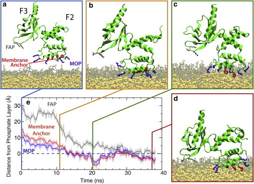
Distinct stages in the membrane binding of talin F2F3. (a; blue frame) Initial configuration of the talin F2F3 subdomain (green cartoon) in a DBPS HMMM system (DBPS, brown; DCLE, yellow). Residues participating in membrane association/insertion are shown as sticks (MOP residues, blue; membrane anchor, red; FAP residues, gray). The membrane is translucent in the snapshots to clearly demonstrate the structural transitions involved in membrane binding. (b–d) The three distinct stages in talin membrane association and insertion; talin F2F3 is initially attracted to the anionic membrane via the basic MOP (b; orange frame), followed by exposure and membrane insertion of the Phe-rich hydrophobic anchor (c; green frame), and a large interdomain conformational change that also brings the F3 subdomain into contact with the membrane via the FAP (d; red frame). (e) Plot of the height of membrane binding moieties above the phosphate layer (dashed line). The phosphate layer was taken to be the instantaneous average of the phosphorous atoms’ z coordinate in the cis-leaflet of the membrane. The membrane-binding moieties (i.e., MOP, FAP, and membrane anchor) are represented by the center-of-mass of their constituent Cα atoms. (Solid lines) Running averages of the transparent curves. To see this figure in color, go online.
Simulation protocols
All simulations were performed using the software NAMD2 (University of Illinois at Urbana-Champaign; http://www.ks.uiuc.edu/Research/namd/) (48) utilizing the CHARMM27 set of force-field parameters with ϕ/ψ cross-term map corrections (49) for proteins and the CHARMM36 (50,51) set of parameters for lipids and DCLE. Topology and parameter files for DBPS were developed using POPS as a template (36) and simply shortening the fatty acid tails to four carbons. The TIP3P model (52) was used for water. The target pressure was set to 1.0 atm, the temperature of the system was set to 310 K, and the time step used was 2.0 fs. Constant pressure was maintained using the Nosé-Hoover Langevin piston method (53,54). A Langevin damping coefficient, γ, of 1 ps−1 was used to maintain the temperature of the system. Nonbonded interactions were cut off after 12 Å with a smoothing function applied after 10 Å. Long-range electrostatic interactions were treated using the particle-mesh Ewald (PME) method (55) with a grid density >1 Å−3. Bonded and nonbonded forces were calculated every time step, while PME calculations were performed every other time step.
Electrostatic potential calculations
The electrostatic potential maps were calculated using the PMEPOT plugin (56) of VMD to study the general electrostatic features of talin F2F3 and how it might affect membrane binding. Because electrostatic calculations utilizing the PME method (55) rely on the periodic bounding box of the simulation, rotation/translation of the molecule can complicate proper averaging of the potential around the protein. Moreover, the edges of the bounding box are also prone to error. Therefore, to obtain accurate potentials at the surface of talin, a separate solution system was constructed similar to the one above in which talin was harmonically restrained (k = 7.5 kcal⋅mol−1 Å−2) at four Cα atoms, two from the F2 subdomain (P211 and C238) and two from the F3 subdomain (P330 and T357), to prevent rotation and translation while allowing for local rearrangements of side chains. After energy minimization and 1 ns of equilibration, the system was simulated for 5 ns. The backbone of talin in each frame was superimposed on the backbone of the initial conformation to remove rotational and translational movements and the potential was calculated every 0.05 ns for 5 ns with a grid resolution of 1 Å−3 and averaged over the trajectory.
Results
The simulations reported herein produced a well-equilibrated and reproducible model of the membrane-bound talin F2F3 subdomain (herein referred to as “talin F2F3”), which was used to explore talin’s initial association and subsequent penetration into the membrane. Starting with a random orientation of talin with respect to the membrane, five independent simulations, which can tumble through ∼20° before binding the membrane (see Table S1 in the Supporting Material), showed spontaneous binding and insertion into an anionic PS HMMM (highly mobile membrane mimetic), with the bound state maintained for the remainder of the simulations. In Fig. 1 (and see Movie S1 in the Supporting Material), the three distinct steps of talin membrane-binding characterized by these simulations, together with specific molecular events involved in the process, are shown for one of the membrane-binding simulations (see Fig. S2 for data on all five simulations). These steps are the following:
-
1.
Attraction of a highly positive residue patch (MOP) in the F2 subdomain to the anionic surface of the membrane (Fig. 1, a and b);
-
2.
Release of an initially buried membrane anchor, which anchors talin F2F3 to the membrane (Fig. 1, b and c); and
-
3.
A large-scale, membrane-induced conformational change between the F2 and F3 subdomains that also brings the F3 subdomain into contact with the membrane via a triad of residues termed the “F3 association patch” (FAP) (Fig. 1, c and d).
The same trend in relative penetration depth of the MOP, FAP, and Phe-rich membrane anchor is observed across all five independent simulations. The absolute penetration depth varies between the five simulations, however, which is to be expected due to the fluid and highly dynamic nature of the membrane surface. This study represents, to the best of our knowledge, the first description of a Phe-rich membrane anchor, identifying the residues responsible for hydrophobic interaction between talin and the membrane. The large-scale conformational change consistently observed in our simulations reconciles the discrepancy between mutagenesis studies (23), which proposed contacts between basic faces of both the F2 and F3 subdomains and the membrane, and structural studies (21,25,28), which have only been able to characterize solution forms of the head domain arranged such that membrane-binding of the MOP in the F2 subdomain prevents binding of the F3 subdomain. These features are discussed in more detail in the following sections.
Electrostatic steering of the F2 subdomain
Mutagenesis studies have demonstrated the critical role of the positively charged MOP, specifically residues K258, K274, R276, and K280, in the membrane association of the talin head domain (21,23,26,28). Therefore, we placed talin F2F3 with these residues oriented toward the membrane, but at a height of 15 Å above the membrane surface. The slow dynamics of lipids on the timescales accessible to MD causes difficulties in sampling protein-lipid interactions using conventional models of lipid bilayers and makes studying the membrane insertion of peripheral proteins, such as talin, prohibitively costly. Because of these difficulties, we utilized our recently developed membrane mimetic system, termed the “HMMM model” (36), which, due to the increased lateral diffusion of lipids, expedites membrane insertion dynamics without compromising the atomistic details that are key to proper description of protein-lipid interactions. Despite the increased lateral mobility in the HMMM, we have shown that the most pertinent properties of the membrane, such as atomic density profiles, area per lipid, and energetics of sidechain-lipid interactions with the headgroup and beginning of the acyl tails, are conserved (36,45). Using a PS HMMM system, we were able to capture spontaneous membrane binding of talin (i.e., in the absence of an external force or biasing potential to artificially induce membrane binding) in five independent simulations (see Fig. S2).
As anticipated from mutagenesis studies (21,28), the MOP residues of the F2 subdomain described above make initial contact with the anionic surface of the membrane very rapidly (in <10 ns in all simulations). However, our simulations also characterized additional membrane-binding residues, specifically H255, K256, K265, K270, and K287 (Fig. 2, and see Table S2). Although these residues have not been reported previously, they appear to interact nonspecifically with the charged surface of the bilayer (see Table S2). These additional interactions observed in the simulation could be due to the highly charged nature of our membrane, but these basic residues reside in the headgroup region when talin is bound to the membrane. Therefore, we believe that these residues are significant even in more physiologically relevant membranes. Once talin is bound to the membrane, as judged by the insertion of the Phe-rich membrane anchor (see below), it coordinates ∼12 lipids closely: 10.1 via basic MOP residues in F2 and 1.8 via the FAP in F3 averaged over the last 10 ns of all five trajectories, which represents the fully membrane-bound state.
Figure 2.
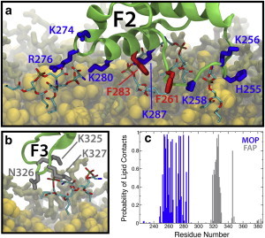
Membrane-bound configurations of the F2 and F3 subdomains. (a) Snapshot showing the F2 subdomain bound to the membrane via MOP residues (blue) and the hydrophobic anchor (red). (b) The F3 subdomain bound the membrane via the FAP residues K325, N326, and K327 (gray). PS headgroups within 3.5 Å of labeled residues are shown as sticks. (Green) Talin backbone; (yellow) DCLE; and (brown) noninteracting PS headgroups. Some of the lipids are not shown for clarity. (c) Probability of phospholipid contacts as a function of residue number in membrane-bound talin for the MOP (blue) and FAP (gray). Residues outside the range shown in the figure had no contact with lipids and are therefore not displayed. The number of lipids in contact with each residue was calculated every 0.05 ns for the last 10 ns of each trajectory and then averaged across the five trajectories. Detailed error estimates for the contact probabilities are given in Table S1 in the Supporting Material for both sidechain-lipid and backbone-lipid interactions. To see this figure in color, go online.
To study the overall electrostatic forces involved in binding of talin to the PS membrane surface, the electrostatic potential map of talin was calculated using a separate simulation performed in aqueous solution, i.e., in the absence of the membrane (Fig. 3). The map reveals, interestingly, the highly polarized electrostatic character of talin F2F3. The underside of talin is a largely positive surface, which is consistent with our understanding of the role of the MOP in talin-membrane interaction. This positive potential can strongly contribute to the protein’s gravitation toward the anionic surface of the membrane, as observed in our simulations. In contrast to the strongly positive underside, the other three faces of talin are decorated with acidic residues (e.g., D194, D203, D207, D210, E291, and E294) generating largely negative potentials (Fig. 3). The highly polarized nature of talin F2F3 is expected to minimize improper orientation of the peripheral protein with respect to the anionic surface of the membrane. Presenting positive residues on the surface meant to bind the membrane, while expressing negatively charged residues on the opposite faces, seems an effective strategy for talin to minimize the number of unproductive encounters with anionic membranes.
Figure 3.
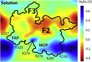
Electrostatic potential map of talin F2F3. The electrostatic potential is calculated using the last 5 ns of a solution simulation at 0.05-ns intervals and using a grid spacing of 1 Å−3. The electrostatic potential at each point was then averaged over the entire 5 ns and plotted. A cross-section of the three-dimensional potential passing through the middle of the protein is shown. (Black line) The contour of talin F2F3 with the positions of the FAP, MOP, and key residues labeled. To see this figure in color, go online.
Identification of a hidden hydrophobic anchor
The insertion of a hydrophobic anchor into the membrane’s core provides a strong stabilizing force for the membrane-bound forms of peripheral proteins (57–59). Although electrostatic interactions do contribute to the overall binding affinity of peripheral proteins to the membrane, they can be readily displaced by water and ions in physiological solutions and are not sufficient for complete binding of peripheral proteins to the membrane. Insertion of a hydrophobic membrane anchor is therefore necessary for complete binding of peripheral proteins to the membrane (36,46,60). As opposed to many other peripheral proteins with clearly exposed hydrophobic anchors (61,62) or lipidated domains that insert into the membrane (63), no membrane anchor is apparent in the crystallographically determined structure of talin F2F3, which represents the solution form of the protein. Previous experimental studies have predicted the presence of a hydrophobic anchor (29,30,34,35). However, description of the anchor, which is essential to understanding the membrane-bound form of talin, has remained elusive to both structural (21,25,26) and computational (28) studies due to the difficulty in fully characterizing the membrane-bound structure.
In our simulations, we have identified two classes of conformational changes on the surface of the membrane that can contribute to hydrophobic anchoring of talin: snorkeling of basic residues (Fig. 4) and insertion of a Phe-rich membrane anchor (Fig. 2 a), neither of which has been previously described, to our knowledge. The two events are connected, inasmuch as snorkeling of basic residues in the MOP allows for the release and insertion of the Phe-rich membrane anchor. After initial association of the MOP basic side chains, residues K256, K258, R276, K280, and K287 begin snorkeling within the membrane headgroup region. Snorkeling within the membrane has been demonstrated to be a mechanism to adopt a favorable conformation that stabilizes membrane proteins (64–66); however, to the best of our knowledge, it has not been reported for membrane association of peripheral proteins to date. The conformational change induced by the membrane causes the side chains of these basic residues, which are initially extended from the bottom of the F2 subdomain (Fig. 4 b), to spread out from the F2 subdomain in the plane of the membrane (Fig. 4 c). This drags the protein deeper into the membrane while simultaneously pushing lipids out from underneath the F2 subdomain. This allows the buried Phe-rich membrane anchor to flip down into the membrane core. The snorkeling of MOP residues supports previous film balance studies (29) in which the area of lipid monolayers increased upon binding of talin, suggesting the protein must force out lipids to fully bind the membrane. Because these conformational changes require only side-chain rearrangements, the timescale of these membrane-binding simulations is expected to be sufficient to describe adequately the observed snorkeling phenomenon.
Figure 4.
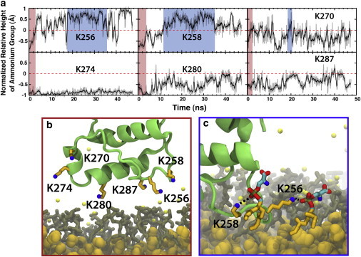
Snorkeling of MOP residues. (a) Relative height of lysine terminal ammonium nitrogen (Nε) above the Cγ normalized by the distance between these atoms for K256, K258, K270, K274, K280, and K287. (Red-shaded areas of these plots) Initial association of talin in which the lysines are still in their extended conformations and point toward the surface of the membrane, as exemplified in panel b for one of the five simulations. (Blue-shaded areas in the plots of K256 and K258) Snorkeling of the lysine residues in which the terminal ammonium nitrogen is in contact with the phosphate while the alkyl chain is embedded deeper in the membrane core. (c) Blue-framed snapshot, which displays the snorkeling of K256 and K258. (Green) Talin backbone; (orange) alkyl chain of lysine; (blue) terminal ammonium nitrogen; (brown) DBPS; and (yellow, van der Waals spheres) DCLEs. To see this figure in color, go online.
Although the snorkeling of lysine residues in talin F2 provides some hydrophobic stabilization to the membrane-bound talin F2F3, the insertion of the Phe-rich membrane anchor is expected to contribute the majority of hydrophobic stabilization to the membrane-bound form of talin. Snorkeling of basic residues drive the F2 subdomain further into the membrane, allowing for the release and insertion of the Phe-rich membrane anchor composed of residues F261 and F283 (Fig. 2 a). These two phenylalanine residues are initially buried deep within the F2 subdomain in a hydrophobic pocket consisting of F249, F261, F267, and F283, together with other smaller hydrophobic residues; however, a local conformational change, together with side-chain rotation of the phenylalanines, allows for insertion of the Phe-rich membrane anchor. To evaluate the extent of exposure of the Phe-rich membrane anchor, we measured the solvent-accessible surface area (SASA) of these two residues in the solution simulation, in which these residues are buried within the protein, and across the five independent membrane-binding trajectories. At a probe radius of 1.5 Å, approximately the radius of a water molecule, the SASA is 273.04 ± 5.98 Å2 in the solution simulation versus 524.72 ± 44.43 Å2 in the bound state. This suggests that binding the membrane induces exposure of this Phe-rich membrane anchor. Root-mean-square deviation (RMSD) measurements of the MOP/anchor backbone and side chains (Table 1) show that the backbone is relatively stable throughout both solution and membrane-binding simulations. However, upon membrane binding, there are large side-chain rearrangements (i.e., snorkeling of lysine residues and flipping down of the Phe-rich membrane anchor) that aid the protein in fully binding the membrane. Together, the SASA and RMSD support the idea that membrane binding induces a structural change in the MOP that exposes the Phe-rich anchor (F261/F283) to the membrane core. Once the Phe-rich anchor is inserted, the protein remains stably bound to the membrane for the duration of the simulation in all five cases (see Fig. S2).
Table 1.
Average internal RMSD values (±SD) during the solution and membrane-binding simulations of talin
| Structure | Solution | Membrane |
|---|---|---|
| F2 subdomain | 0.96 ± 0.10 | 2.18 ± 1.48 |
| F3 subdomain | 1.91 ± 1.38 | 2.31 ± 1.82 |
| MOP/anchor | ||
| Backbone only | 0.82 ± 0.09 | 1.18 ± 1.09 |
| All heavy atoms | 1.03 ± 0.11 | 10.36 ± 0.77 |
Shown for the F2 subdomain backbone (residues 206–306), the F3 subdomain backbone (residues 312–408), and the MOP/Phe-rich anchor region (residues 250–290). In each calculation, the reference structure was given by the first frame of the trajectory and the protein backbone was superimposed on the reference each frame. The RMSD was calculated every 0.05 ns for the last 10 ns of each trajectory and then averaged across all five membrane-binding trajectories.
Membrane-induced rearrangement of the F2 and F3 subdomains
The talin F2F3 crystal structure depicts the canonical arrangement of talin subdomains (4,21,25) in which the F1 and F3 subdomains sit higher than the F2 subdomain, producing an overall structure that resembles a cloverleaf (see Fig. S1). This conformation prevents simultaneous interaction of the basic faces of the F2 and F3 subdomains (MOP and FAP, respectively) with the membrane surface. However, mutagenesis studies have shown that the F3 subdomain must interact with the surface of the membrane to activate integrin (23,32). Additionally, our electrostatics calculations (Fig. 3) predict strong interaction between the largely positive potential of the FAP and the anionic surface of the membrane. Because the F3 subdomain is the point of interaction between talin and integrin (20), a full description of its behavior (structure and dynamics) in the presence of the membrane is key to our understanding of how talin modulates integrin activity.
In each of the simulations performed, after the insertion of the F2 subdomain we observe attraction of the F3 subdomain to the surface of the membrane (Fig. 1 and see Fig. S2) manifested by spontaneous binding of the F3 subdomain to the membrane surface via residues K325, N326, and K327 (Fig. 2). This observation agrees with mutagenesis studies (23,32) demonstrating weaker membrane binding of talin upon neutralization of these charged residues. The internal backbone RMSD of the F3 subdomain is relatively small (Table 1); however, it undergoes a large structural reorientation with respect to the F2 subdomain (Fig. 5), representing the largest membrane-induced effect observed in our simulations. A control simulation of talin in solution clearly indicates that this phenomenon is membrane-induced as opposed to general relaxation of the protein from the crystal structure.
Figure 5.
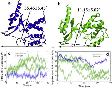
Membrane-induced interdomain conformational change talin F2F3. Representative snapshots of talin F2F3 during a solution (a; blue cartoon) and membrane-binding (b; green cartoon) simulation. The snapshots shown here were taken at t = 30 ns, which corresponds to talin being bound to the membrane in panel b. (c) RMSD of the F3 subdomain (residues 312–408) relative to the F2 subdomain (residues 192–311) for membrane (green) and solution (blue) simulations. For both simulations, the protein backbone of the F2 subdomain was superimposed on the initial structure and the backbone RMSD of the F3 subdomain was measured at 0.05-ns intervals. (Solid line) Running average (taken in 0.5-ns intervals); (transparent curve) true RMSD. (d) Plot of the angle between the F2 and F3 subdomains. In this measurement, the protein backbone of the F2 subdomain was superimposed on the initial structure and the angle between the reference vector and the vector created by center of mass of the MOP backbone atoms and the FAP backbone atoms (dashed vector) was measured at 0.05-ns intervals. The reference for the measured angle (solid vector) was taken to be the xy plane as talin was placed in these system such that the MOP faced the xy plane. (Solid line) Running average taken over 0.5-ns intervals; (transparent curve) instantaneous angle. To see this figure in color, go online.
Although some structural fluctuation of talin F2F3 is observed during the solution simulation (Fig. 5), indicating the inherent interdomain flexibility of talin F2F3, the structural fluctuations are, by far, smaller than those observed in the presence of the membrane and are not sustained throughout the simulation. Moreover, measurement of the angle between the F2 and F3 subdomains (Fig. 5) shows that there is a distinct rotation of the F3 subdomain relative to the F2 subdomain induced by the membrane. The angle between the F2 and F3 subdomains is much smaller when binding the membrane (11.2 ± 5.0°) versus the same angle measured in a control solution simulation (35.5 ± 5.5°). To properly bind the membrane, the F2 and F3 subdomains undergo internal structural rearrangements that are not observed in the solution simulations, as evidenced by RMSD and interdomain angle of the solution and membrane-binding simulations (Table 1, Fig. 5). The F3 subdomain is thought to disrupt a highly conserved, intermolecular salt bridge between the integrin α- and β-tails, leading to integrin activation (3,4,6,12,8,13). NMR studies (21) have demonstrated that residues K325 and K327 in the talin F3 subdomain intimately interact with this salt bridge; however, the role of the F3 subdomain in integrin activation cannot be ascertained from the structures (21,25,28), which precludes the simultaneous binding of both the F2 and F3 subdomains. Our simulations demonstrate that residues K325 and K327 bind to the membrane, but only superficially (Fig. 1 e and Fig. 2 b), sitting on the surface of the membrane (∼1.5 Å above the phosphate layer) and coordinating ∼3 phospholipids (see Table S2) and, therefore, those residues would still be optimally positioned to interact with integrin. Moreover, it is only after the large, membrane-induced conformational change observed in our simulations that talin would be positioned to properly interact with the acidic residue on the integrin β-tail and cause disruption of the conserved salt bridge, leading to integrin activation.
Membrane-bound talin remains stable in a DOPS membrane
Although the HMMM model does allow for expedited membrane binding and sampling of protein-lipid interactions, the model was not necessarily designed to, and indeed may not, completely reproduce the mechanical and electrical properties of a conventional membrane. Therefore, to explore whether the membrane-bound model of talin proposed by simulations using the HMMM model are stable and accurate, we grew a DOPS (1,2-dioleyl-sn-glycero-3-phosphatidylserine) membrane around the membrane-bound talin (see Methods for further details on the membrane growing process). Over successively decreasing levels of restraint, the DOPS membrane was allowed to adapt to the membrane-bound conformation of talin, while keeping the backbone of talin F2F3 harmonically constrained. Once equilibrated, the talin F2F3/DOPS system was simulated for 100 ns. In Fig. S3, the timecourse of both the area per lipid and membrane width have been plotted over the entire simulation to demonstrate the structural convergence of the full DOPS membrane, which was grown around the inserted talin F2F3 subdomain. After ∼40 ns, these measurements have plateaued and the membrane can be deemed sufficiently relaxed. The internal structure of the protein remains stable throughout the 100-ns simulation, with the average talin F2F3 backbone RMSD <3 Å, the average F2 subdomain RMSD of 1.63, and the average F3 subdomain RMSD of 2.54 Å (see Table S3). Although there is a slight decrease in the depth of penetration of talin (<5 Å), the protein remains stably bound to the DOPS membrane for the duration of the simulation (see Fig. S4), with the Phe-rich membrane anchor remaining inserted into the DOPS bilayer and the FAP and MOP residues remaining in contact with the membrane. Therefore, the membrane-bound model of talin F2F3 observed in five independent simulations using a PS HMMM model is a stable conformation of talin, and suggests that the results garnered from the HMMM model studies represent physiologically relevant states important for understanding talin membrane binding and the effect of membrane-bound talin on integrin activation.
Discussion
The process of talin-dependent activation of integrin is heavily dependent on membrane-binding of talin and associated protein structural changes. Therefore, detailed structural descriptions of both membrane-bound talin as well as the talin/integrin complex are indispensable to understanding this vital system. In this study, we present an atomic detailed model of the membrane-bound state of talin F2F3 and describe membrane-induced structural transitions that suggest a putative mechanism for why membrane-binding is a key process in talin-mediated activation of integrin.
By utilizing a novel membrane representation (36), which allows for efficient sampling of talin-membrane interactions at an atomic resolution, we were able to capture the spontaneous binding of talin F2F3 to the membrane in multiple, independent simulations. We observed that membrane binding of talin occurs as three distinct events (Figs. 1 and 6), namely:
-
1.
Nonspecific electrostatic steering of the basic MOP residues in the F2 subdomain to the anionic surface of the membrane facilitated by the polarized electrostatic nature of the protein;
-
2.
Release and insertion of a conserved, initially buried Phe-rich membrane anchor aided by the snorkeling of MOP residues; and
-
3.
Large-scale, interdomain conformational change enabling the F3 subdomain to directly engage in membrane interaction via a triad of residues in the FAP.
All simulations show the same trend in regards to insertion of the MOP, FAP, and Phe-rich anchor, but subtle differences in absolute penetration depths between simulations demonstrate the fluid and dynamic nature of the membrane itself. It should be noted that the model of talin/integrin activation in Fig. 6 is speculative, and more work needs to be performed to elucidate the fundamental interactions dictating talin-mediated integrin activation and the role that the conformational changes herein described have in that process.
Figure 6.
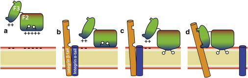
A model for membrane-mediated activation of integrin by talin. Cytosolic talin F2F3 (a) is initially attracted to the anionic surface of the membrane (red layer) by the positively charged MOP residues (blue area in the F2 subdomain). Once the F2 subdomain associates with the membrane (b), basic MOP residues in the F2 subdomain begin snorkeling within the membrane, leading to a local conformational change (c), which allows the Phe-rich hydrophobic anchor to be inserted into the membrane core and anchor talin to the membrane. After this event, the positive residues of the FAP (blue area in the F3 subdomain) are attracted to the anionic surface of the membrane, leading to an interdomain conformational change in which the F3 subdomain also makes contact with the membrane surface (d). Once the F3 subdomain associates with the membrane surface, it is optimally positioned to interact properly with the two activating sites on integrin β-tail (orange helix). These interactions promote separation of the native integrin complex (d), consisting of integrin α-tail (blue helix) bound to the β-tail, leading to integrin activation. To see this figure in color, go online.
In addition to the basic residues previously proposed (Anthis et al. (21), Saltel et al. (23), and Kalli et al. (28)), our simulations have elucidated the involvement of additional residues in the MOP, which are conserved across multiple species. Interestingly, we were also able to observe a few of the MOP residues snorkeling within the membrane, reporting for the first time to our knowledge, the involvement of such a mechanism in membrane binding of a peripheral protein. The simulations reported herein have also identified a membrane anchor composed of phenylalanine residues that insert into the membrane after the snorkeling of MOP basic residues. Although a membrane anchor had been suspected to exist, none had been identified before this study.
Lastly, our simulations have revealed a large, interdomain conformational change of the F3 subdomain, which reconciles previous mutagenesis studies with the available crystallographic and NMR structures of talin obtained in the absence of membrane. Driven by general (nonspecific) electrostatic attraction, the F3 subdomain rotates relative to the F2 subdomain, coming into direct contact with the membrane via the FAP. This conformational change is reminiscent of a recent crystal structure of the entire talin head domain (26), which shows an elongated, co-linear structure for the F1–F3 subdomains, as opposed to the commonly accepted cloverleaf arrangement. This provides experimental evidence that the conformational change seen in these simulations is accessible to the protein. However, this structure was acquired in the absence of the membrane and, therefore, lacks the atomic-level detail of membrane bound talin found in this report.
Because the full talin head structure was not available at the commencement of this study, we have only studied the dynamics of the F2F3 subdomain in the presence of the membrane. It can be speculated, however, that due to the relatively unstructured regions between subdomains, that the same conformational changes would be observed in the full head domain construct. Notably, the conformational change appears to be of the magnitude needed for integrin activation through mechanical coupling of the two proteins. Both the HMMM and full membrane simulations utilize a system composed of 100% PS molecules to increase the probability of observing a binding event. We are unsure whether this has any effect on the structure of the membrane-bound form. We note, however, that it is very difficult to know the local concentration of differing types of lipid molecules surrounding the protein experimentally, making it a challenging task to model the local environment of the protein in MD simulations. As of this writing, we are working with smaller membrane anchoring domains to resolve how different local concentrations of lipids can affect protein structure once bound to the membrane. We are also in the process of studying how PIP2 affects the membrane-bound state of talin. However, there is a lack of accurate parameters for these signaling lipids and the majority of our effort in this area has gone into parameterizing these unique lipids.
Although the HMMM model effectively decreases the time needed to observe spontaneous membrane insertion of peripheral proteins, it is not expected to reproduce certain physical properties of membranes such as volume/area compressibility and bending moduli by design. This model is intended to provide a more dynamic platform for peripheral protein insertion, facilitating rapid rearrangement and displacement of lipids and allowing for collection of sufficient statistics to propose reliable structural models. Due to the fact that the headgroup region of the HMMM is identical to a conventional membrane, we expect lipid-protein interactions in this region to be unchanged by use of the HMMM model. Indeed, upon conversion of the HMMM membrane to a conventional DOPS membrane, the membrane-bound form of talin was unperturbed, retaining both the global subdomain arrangement and the local lipid-protein interactions.
Acknowledgments
The authors thank Mark McLean, Stephen G. Sligar, and James H. Morrissey for insightful discussion.
This work was supported in part by the National Institutes of Health (grants No. R01-GM101048, No. R01-GM086749, No. U54-GM087519, and No. P41-GM104601 to E.T. and Molecular Biophysics Training Grant to M.J.A.) and the National Science Foundation (Graduate Research Fellowship to M.J.A.). All simulations have been performed at XSEDE resources (grant No. MCA06N060).
Supporting Material
References
- 1.Burridge K., Connell L. A new protein of adhesion plaques and ruffling membranes. J. Cell Biol. 1983;97:359–367. doi: 10.1083/jcb.97.2.359. [DOI] [PMC free article] [PubMed] [Google Scholar]
- 2.Tadokoro S., Shattil S.J., Calderwood D.A. Talin binding to integrin β tails: a final common step in integrin activation. Science. 2003;302:103–106. doi: 10.1126/science.1086652. [DOI] [PubMed] [Google Scholar]
- 3.Shattil S.J., Kim C., Ginsberg M.H. The final steps of integrin activation: the end game. Nat. Rev. Mol. Cell Biol. 2010;11:288–300. doi: 10.1038/nrm2871. [DOI] [PMC free article] [PubMed] [Google Scholar]
- 4.Critchley D.R. Biochemical and structural properties of the integrin-associated cytoskeletal protein talin. Annu. Rev. Biophys. 2009;38:235–254. doi: 10.1146/annurev.biophys.050708.133744. [DOI] [PubMed] [Google Scholar]
- 5.Hynes R.O. Integrins: bidirectional, allosteric signaling machines. Cell. 2002;110:673–687. doi: 10.1016/s0092-8674(02)00971-6. [DOI] [PubMed] [Google Scholar]
- 6.Liddington R.C., Ginsberg M.H. Integrin activation takes shape. J. Cell Biol. 2002;158:833–839. doi: 10.1083/jcb.200206011. [DOI] [PMC free article] [PubMed] [Google Scholar]
- 7.Felding-Habermann B., Lerner R.A., Janda K.D. Combinatorial antibody libraries from cancer patients yield ligand-mimetic Arg-Gly-Asp-containing immunoglobulins that inhibit breast cancer metastasis. Proc. Natl. Acad. Sci. USA. 2004;101:17210–17215. doi: 10.1073/pnas.0407869101. [DOI] [PMC free article] [PubMed] [Google Scholar]
- 8.Ginsberg M.H., Partridge A., Shattil S.J. Integrin regulation. Curr. Opin. Cell Biol. 2005;17:509–516. doi: 10.1016/j.ceb.2005.08.010. [DOI] [PubMed] [Google Scholar]
- 9.Ma Y.Q., Qin J., Plow E.F. Platelet integrin αIIbβ3: activation mechanisms. J. Thromb. Haemost. 2007;5:1345–1352. doi: 10.1111/j.1538-7836.2007.02537.x. [DOI] [PubMed] [Google Scholar]
- 10.Humphries M.J., McEwan P.A., Mould A.P. Integrin structure: heady advances in ligand binding, but activation still makes the knees wobble. Trends Biochem. Sci. 2003;28:313–320. doi: 10.1016/s0968-0004(03)00112-9. [DOI] [PubMed] [Google Scholar]
- 11.Wegener K.L., Campbell I.D. Transmembrane and cytoplasmic domains in integrin activation and protein-protein interactions (review) Mol. Membr. Biol. 2008;25:376–387. doi: 10.1080/09687680802269886. [DOI] [PMC free article] [PubMed] [Google Scholar]
- 12.Ratnikov B.I., Partridge A.W., Ginsberg M.H. Integrin activation by talin. J. Thromb. Haemost. 2005;3:1783–1790. doi: 10.1111/j.1538-7836.2005.01362.x. [DOI] [PubMed] [Google Scholar]
- 13.Campbell I.D., Ginsberg M.H. The talin-tail interaction places integrin activation on FERM ground. Trends Biochem. Sci. 2004;29:429–435. doi: 10.1016/j.tibs.2004.06.005. [DOI] [PubMed] [Google Scholar]
- 14.Moser M., Legate K.R., Fässler R. The tail of integrins, talin, and kindlins. Science. 2009;324:895–899. doi: 10.1126/science.1163865. [DOI] [PubMed] [Google Scholar]
- 15.Rees D.J., Ades S.E., Hynes R.O. Sequence and domain structure of talin. Nature. 1990;347:685–689. doi: 10.1038/347685a0. [DOI] [PubMed] [Google Scholar]
- 16.Muguruma M., Nishimuta S., Matsumura S. Organization of the functional domains in membrane cytoskeletal protein talin. J. Biochem. 1995;117:1036–1042. doi: 10.1093/oxfordjournals.jbchem.a124803. [DOI] [PubMed] [Google Scholar]
- 17.Goult B.T., Bouaouina M., Barsukov I.L. Structure of a double ubiquitin-like domain in the talin head: a role in integrin activation. EMBO J. 2010;29:1069–1080. doi: 10.1038/emboj.2010.4. [DOI] [PMC free article] [PubMed] [Google Scholar]
- 18.Calderwood D.A., Zent R., Ginsberg M.H. The talin head domain binds to integrin β subunit cytoplasmic tails and regulates integrin activation. J. Biol. Chem. 1999;274:28071–28074. doi: 10.1074/jbc.274.40.28071. [DOI] [PubMed] [Google Scholar]
- 19.Kim M., Carman C.V., Springer T.A. Bidirectional transmembrane signaling by cytoplasmic domain separation in integrins. Science. 2003;301:1720–1725. doi: 10.1126/science.1084174. [DOI] [PubMed] [Google Scholar]
- 20.Calderwood D.A., Yan B., Ginsberg M.H. The phosphotyrosine binding-like domain of talin activates integrins. J. Biol. Chem. 2002;277:21749–21758. doi: 10.1074/jbc.M111996200. [DOI] [PubMed] [Google Scholar]
- 21.Anthis N.J., Wegener K.L., Campbell I.D. The structure of an integrin/talin complex reveals the basis of inside-out signal transduction. EMBO J. 2009;28:3623–3632. doi: 10.1038/emboj.2009.287. [DOI] [PMC free article] [PubMed] [Google Scholar]
- 22.Martel V., Racaud-Sultan C., Albiges-Rizo C. Conformation, localization, and integrin binding of talin depend on its interaction with phosphoinositides. J. Biol. Chem. 2001;276:21217–21227. doi: 10.1074/jbc.M102373200. [DOI] [PubMed] [Google Scholar]
- 23.Saltel F., Mortier E., Wehrle-Haller B. New PI(4,5)P2- and membrane proximal integrin-binding motifs in the talin head control β3-integrin clustering. J. Cell Biol. 2009;187:715–731. doi: 10.1083/jcb.200908134. [DOI] [PMC free article] [PubMed] [Google Scholar]
- 24.Bouaouina M., Lad Y., Calderwood D.A. The N-terminal domains of talin cooperate with the phosphotyrosine binding-like domain to activate β1 and β3 integrins. J. Biol. Chem. 2008;283:6118–6125. doi: 10.1074/jbc.M709527200. [DOI] [PubMed] [Google Scholar]
- 25.García-Alvarez B., de Pereda J.M., Liddington R.C. Structural determinants of integrin recognition by talin. Mol. Cell. 2003;11:49–58. doi: 10.1016/s1097-2765(02)00823-7. [DOI] [PubMed] [Google Scholar]
- 26.Elliott P.R., Goult B.T., Barsukov I.L. The structure of the talin head reveals a novel extended conformation of the FERM domain. Structure. 2010;18:1289–1299. doi: 10.1016/j.str.2010.07.011. [DOI] [PMC free article] [PubMed] [Google Scholar]
- 27.Song X., Yang J., Qin J. A novel membrane-dependent on/off switch mechanism of talin FERM domain at sites of cell adhesion. Cell Res. 2012;22:1533–1545. doi: 10.1038/cr.2012.97. [DOI] [PMC free article] [PubMed] [Google Scholar]
- 28.Kalli A.C., Wegener K.L., Sansom M.S. The structure of the talin/integrin complex at a lipid bilayer: an NMR and MD simulation study. Structure. 2010;18:1280–1288. doi: 10.1016/j.str.2010.07.012. [DOI] [PMC free article] [PubMed] [Google Scholar]
- 29.Dietrich C., Goldmann W.H., Isenberg G. Interaction of NBD-talin with lipid monolayers. A film balance study. FEBS Lett. 1993;324:37–40. doi: 10.1016/0014-5793(93)81527-7. [DOI] [PubMed] [Google Scholar]
- 30.Isenberg G., Goldmann W.H. Peptide-specific antibodies localize the major lipid binding sites of talin dimers to oppositely arranged N-terminal 47 kDa subdomains. FEBS Lett. 1998;426:165–170. doi: 10.1016/s0014-5793(98)00336-6. [DOI] [PubMed] [Google Scholar]
- 31.Seelert H., Poetsch A., Müller D.J. Structural biology. Proton-powered turbine of a plant motor. Nature. 2000;405:418–419. doi: 10.1038/35013148. [DOI] [PubMed] [Google Scholar]
- 32.Wegener K.L., Partridge A.W., Campbell I.D. Structural basis of integrin activation by talin. Cell. 2007;128:171–182. doi: 10.1016/j.cell.2006.10.048. [DOI] [PubMed] [Google Scholar]
- 33.Anthis N.J., Wegener K.L., Campbell I.D. Structural diversity in integrin/talin interactions. Structure. 2010;18:1654–1666. doi: 10.1016/j.str.2010.09.018. [DOI] [PMC free article] [PubMed] [Google Scholar]
- 34.Seelig A., Blatter X.L., Isenberg G. Phospholipid binding of synthetic talin peptides provides evidence for an intrinsic membrane anchor of talin. J. Biol. Chem. 2000;275:17954–17961. doi: 10.1074/jbc.M002264200. [DOI] [PubMed] [Google Scholar]
- 35.Tempel M., Goldmann W.H., Sackmann E. Interaction of the 47-kDa talin fragment and the 32-kDa vinculin fragment with acidic phospholipids: a computer analysis. Biophys. J. 1995;69:228–241. doi: 10.1016/S0006-3495(95)79894-0. [DOI] [PMC free article] [PubMed] [Google Scholar]
- 36.Ohkubo Y.Z., Pogorelov T.V., Tajkhorshid E. Accelerating membrane insertion of peripheral proteins with a novel membrane mimetic model. Biophys. J. 2012;102:2130–2139. doi: 10.1016/j.bpj.2012.03.015. [DOI] [PMC free article] [PubMed] [Google Scholar]
- 37.Humphrey W., Dalke A., Schulten K. VMD: visual molecular dynamics. J. Mol. Graph. 1996;14:33–38. doi: 10.1016/0263-7855(96)00018-5. 27–28. [DOI] [PubMed] [Google Scholar]
- 38.Bond P.J., Sansom M.S.P. Insertion and assembly of membrane proteins via simulation. J. Am. Chem. Soc. 2006;128:2697–2704. doi: 10.1021/ja0569104. [DOI] [PMC free article] [PubMed] [Google Scholar]
- 39.Shi Q., Izvekov S., Voth G.A. Mixed atomistic and coarse-grained molecular dynamics: simulation of a membrane-bound ion channel. J. Phys. Chem. B. 2006;110:15045–15048. doi: 10.1021/jp062700h. [DOI] [PubMed] [Google Scholar]
- 40.Arkhipov A., Yin Y., Schulten K. Four-scale description of membrane sculpting by BAR domains. Biophys. J. 2008;95:2806–2821. doi: 10.1529/biophysj.108.132563. [DOI] [PMC free article] [PubMed] [Google Scholar]
- 41.Kalli A.C., Campbell I.D., Sansom M.S. Multiscale simulations suggest a mechanism for integrin inside-out activation. Proc. Natl. Acad. Sci. USA. 2011;108:11890–11895. doi: 10.1073/pnas.1104505108. [DOI] [PMC free article] [PubMed] [Google Scholar]
- 42.Im W., Brooks C.L., 3rd Interfacial folding and membrane insertion of designed peptides studied by molecular dynamics simulations. Proc. Natl. Acad. Sci. USA. 2005;102:6771–6776. doi: 10.1073/pnas.0408135102. [DOI] [PMC free article] [PubMed] [Google Scholar]
- 43.Bu L., Im W., Brooks C.L., 3rd Membrane assembly of simple helix homo-oligomers studied via molecular dynamics simulations. Biophys. J. 2007;92:854–863. doi: 10.1529/biophysj.106.095216. [DOI] [PMC free article] [PubMed] [Google Scholar]
- 44.Mondal J., Zhu X., Yethiraj A. Sequence-dependent interaction of β-peptides with membranes. J. Phys. Chem. B. 2010;114:13585–13592. doi: 10.1021/jp1070242. [DOI] [PubMed] [Google Scholar]
- 45.Pogorelov T.V., Vermaas J.V., Tajkhorshid E. Partitioning of amino acids into a model membrane: capturing the interface. J. Phys. Chem. B. 2014;118:1481–1492. doi: 10.1021/jp4089113. [DOI] [PMC free article] [PubMed] [Google Scholar]
- 46.Arcario M.J., Ohkubo Y.Z., Tajkhorshid E. Capturing spontaneous partitioning of peripheral proteins using a biphasic membrane-mimetic model. J. Phys. Chem. B. 2011;115:7029–7037. doi: 10.1021/jp109631y. [DOI] [PMC free article] [PubMed] [Google Scholar]
- 47.Petrache H.I., Tristram-Nagle S., Nagle J.F. Structure and fluctuations of charged phosphatidylserine bilayers in the absence of salt. Biophys. J. 2004;86:1574–1586. doi: 10.1016/S0006-3495(04)74225-3. [DOI] [PMC free article] [PubMed] [Google Scholar]
- 48.Phillips J.C., Braun R., Schulten K. Scalable molecular dynamics with NAMD. J. Comput. Chem. 2005;26:1781–1802. doi: 10.1002/jcc.20289. [DOI] [PMC free article] [PubMed] [Google Scholar]
- 49.MacKerell A.D., Jr., Feig M., Brooks C.L., 3rd Extending the treatment of backbone energetics in protein force fields: limitations of gas-phase quantum mechanics in reproducing protein conformational distributions in molecular dynamics simulations. J. Comput. Chem. 2004;25:1400–1415. doi: 10.1002/jcc.20065. [DOI] [PubMed] [Google Scholar]
- 50.Vanommeslaeghe K., Hatcher E., MacKerell A.D., Jr. CHARMM general force field: a force field for drug-like molecules compatible with the CHARMM all-atom additive biological force fields. J. Comput. Chem. 2010;31:671–690. doi: 10.1002/jcc.21367. [DOI] [PMC free article] [PubMed] [Google Scholar]
- 51.Klauda J.B., Venable R.M., Pastor R.W. Update of the CHARMM all-atom additive force field for lipids: validation on six lipid types. J. Phys. Chem. B. 2010;114:7830–7843. doi: 10.1021/jp101759q. [DOI] [PMC free article] [PubMed] [Google Scholar]
- 52.Jorgensen W.L., Chandrasekhar J., Klein M.L. Comparison of simple potential functions for simulating liquid water. J. Chem. Phys. 1983;79:926–935. [Google Scholar]
- 53.Martyna G.J., Tobias D.J., Klein M.L. Constant pressure molecular dynamics algorithms. J. Chem. Phys. 1994;101:4177–4189. [Google Scholar]
- 54.Feller S.E., Zhang Y., Brooks B.R. Constant pressure molecular dynamics simulation: the Langevin piston method. J. Chem. Phys. 1995;103:4613–4621. [Google Scholar]
- 55.Darden T., York D., Pedersen L.G. Particle mesh Ewald: an N ⋅ log(N) method for Ewald sums in large systems. J. Chem. Phys. 1993;98:10089–10092. [Google Scholar]
- 56.Aksimentiev A., Schulten K. Imaging α-hemolysin with molecular dynamics: ionic conductance, osmotic permeability, and the electrostatic potential map. Biophys. J. 2005;88:3745–3761. doi: 10.1529/biophysj.104.058727. [DOI] [PMC free article] [PubMed] [Google Scholar]
- 57.Jähnig F. Thermodynamics and kinetics of protein incorporation into membranes. Proc. Natl. Acad. Sci. USA. 1983;80:3691–3695. doi: 10.1073/pnas.80.12.3691. [DOI] [PMC free article] [PubMed] [Google Scholar]
- 58.Jacobs R.E., White S.H. The nature of the hydrophobic binding of small peptides at the bilayer interface: implications for the insertion of transbilayer helices. Biochemistry. 1989;28:3421–3437. doi: 10.1021/bi00434a042. [DOI] [PubMed] [Google Scholar]
- 59.Johnson J.E., Cornell R.B. Amphitropic proteins: regulation by reversible membrane interactions (review) Mol. Membr. Biol. 1999;16:217–235. doi: 10.1080/096876899294544. [DOI] [PubMed] [Google Scholar]
- 60.Ohkubo Y.Z., Tajkhorshid E. Distinct structural and adhesive roles of Ca2+ in membrane binding of blood coagulation factors. Structure. 2008;16:72–81. doi: 10.1016/j.str.2007.10.021. [DOI] [PubMed] [Google Scholar]
- 61.Banner D.W., D’Arcy A., Kirchhofer D. The crystal structure of the complex of blood coagulation factor VIIa with soluble tissue factor. Nature. 1996;380:41–46. doi: 10.1038/380041a0. [DOI] [PubMed] [Google Scholar]
- 62.Ngo J.C.K., Huang M., Furie B. Crystal structure of human factor VIII: implications for the formation of the factor IXa-factor VIIIa complex. Structure. 2008;16:597–606. doi: 10.1016/j.str.2008.03.001. [DOI] [PubMed] [Google Scholar]
- 63.Tong L.A., de Vos A.M., Kim S.-H. Crystal structures at 2.2 Å resolution of the catalytic domains of normal ras protein and an oncogenic mutant complexed with GDP. J. Mol. Biol. 1991;217:503–516. doi: 10.1016/0022-2836(91)90753-s. [DOI] [PubMed] [Google Scholar]
- 64.Mishra V.K., Palgunachari M.N., Anantharamaiah G.M. Interactions of synthetic peptide analogs of the class A amphipathic helix with lipids. Evidence for the snorkel hypothesis. J. Biol. Chem. 1994;269:7185–7191. [PubMed] [Google Scholar]
- 65.Strandberg E., Killian J.A. Snorkeling of lysine side chains in transmembrane helices: how easy can it get? FEBS Lett. 2003;544:69–73. doi: 10.1016/s0014-5793(03)00475-7. [DOI] [PubMed] [Google Scholar]
- 66.Deol S.S., Bond P.J., Sansom M.S. Lipid-protein interactions of integral membrane proteins: a comparative simulation study. Biophys. J. 2004;87:3737–3749. doi: 10.1529/biophysj.104.048397. [DOI] [PMC free article] [PubMed] [Google Scholar]
Associated Data
This section collects any data citations, data availability statements, or supplementary materials included in this article.