Abstract
Magnetic Particle Imaging (MPI) is a new biomedical imaging technique that produces real-time, high-resolution tomographic images of superparamagnetic iron oxide nanoparticle tracers. Currently, 25 kHz and 20 mT/μ0 excitation fields are common in MPI, but lower field amplitudes may be necessary for patient safety in future designs. Here, we address fundamental questions about MPI tracer magnetization dynamics and predict tracer performance in future scanners that employ new combinations of excitation field amplitude (Ho) and frequency (ω). Using an optimized, monodisperse MPI tracer, we studied how several combinations of drive field frequencies and amplitudes affect the tracer's response, using Magnetic Particle Spectrometry and AC hysteresis, for drive field conditions at 15.5, 26, and 40.2 kHz, with field amplitudes ranging from 7 to 52 mT/μ0. For both fluid and immobilized nanoparticle samples, we determined that magnetic response was dominated by Néel reversal. Furthermore, we observed that the peak slew-rate (ωHo) determined the tracer magnetic response. Smaller amplitudes provided correspondingly smaller field of view, sometimes resulting in excitation of minor hysteresis loops. Changing the drive field conditions but keeping the peak slew-rate constant kept the tracer response almost the same. Higher peak slew-rates led to reduced maximum signal intensity and greater coercivity in the tracer response. Our experimental results were in reasonable agreement with Stoner-Wohlfarth model based theories.
I. INTRODUCTION
Magnetic particle imaging (MPI) is an emerging medical imaging technique designed to image magnetic nanoparticle tracers. MPI exploits the relatively large but thermally unstable and non-linear response of superparamagnetic nanoparticles to oscillating magnetic fields. Typically, biocompatible magnetite nanoparticles are used in MPI. To acquire an MPI image, a field free point (FFP) is created by strong magnetic field gradients. Then, an alternating drive field (25–150 kHz) generates a tracer response from the FFP region in the form of an induced voltage signal in the receiver coil, which is then reconstructed into an MPI image. In principle, MPI can detect extremely small quantities of magnetic nanoparticles (MNPs), of the order of nanograms,1,2 with a resolution comparable to MRI.
In MPI, MNP tracers are magnetized by an alternating magnetic field and the resulting change in magnetic flux caused by their changing magnetization, m′(H(t)), generates a signal current in a receiver coil. Due to particle dynamics, the tracer's magnetic response varies with the drive field frequency and amplitude, in addition to the properties of the magnetic particles themselves. While most MPI research until now has been conducted with drive fields of ∼25 kHz and amplitudes up to ∼20 mT (40 mT peak to peak), recent studies suggest that alternative conditions will be necessary to ensure patient safety and comfort, since the human body can be sensitive to magnetic fields with high slew rates (dH/dt, or dB/dt). Peripheral nerve stimulation (PNS)3 and tissue heating (specific absorption rate, or SAR)4 are the principle concerns during application of alternating magnetic fields. In a recent study, Saritas et al.5 reported the magnetostimulation threshold amplitude to be about 7.5 mT/μ0 for human torso MPI in the frequency range 25–50 kHz. This finding led us to investigate how MPI tracers would behave under varying field parameters. In previous work, we studied the magnetic response of different sizes of magnetite nanoparticle tracers using a Magnetic Particle Spectrometry (MPS) system built in our laboratory6 to operate at 26 kHz and 20 mT/μ0. This study reports our investigation of the tracer response over a range of drive field frequencies (15.5, 26, and 40.2 kHz) and amplitudes (7.5, 32, and 50 mT/μ0), and observation that MPI tracer behavior varies with the peak slew-rate (SL). We will refer to the peak slew-rate, ωH0, or the product of angular frequency, ω, and drive field amplitude, H0, though during experiments the slew rate varied with time due to the sinusoidal excitation field. In this study, we used monodisperse tracers previously optimized for MPI to ensure that variations in the tracer response during experiments arose from uniform variation in the response of each particle, in both the fluid and immobilized tracer samples. Our results are also relevant for magnetic hyperthermia applications, because tailoring the material parameters of MNPs for specific alternating magnetic field conditions (frequency and amplitude) leads to optimization of the power loss and helps attain maximum heat dissipation.7,8
II. MATERIALS AND METHODS
A. Synthesis and characterization of Fe3O4 MNPs
Magnetite (Fe3O4) nanoparticles (MNPs) were synthesized by the pyrolysis of the Fe(III)oleate precursor with excess oleic acid surfactant in 1-octadecene. After synthesis, oleic acid coated magnetite nanoparticles were transferred from organic to aqueous phase using a PEGylated amphiphilic polymer [poly(maleic anhydride-alt-1 octadecene)-poly(-ethylene glycol); PEGMn = 20 kDa]. Detailed synthesis and phase transfer methods have been reported previously.8–11 The two samples studied in this work, named LS-1 and LS-1-3, were prepared in separate phase transfer reactions, from the same batch of magnetic cores and polymer coating. Immobilized nanoparticles (LS-1-3) were prepared by suspending the nanoparticles in dimethyl sulfoxide (DMSO) and then freezing at −20 °C.
VSM curves of the ferrofluid (containing 100–200 μg MNPs) were fit to the Langevin function to obtain the median magnetic core diameter, D0, and distribution.12 MNPs were also analyzed using a transmission electron microscope (TEM) (FEI Tecnai G2F20) to evaluate particle morphology and measure the average crystal diameter and size distribution. To understand the colloidal properties of MNPs, hydrodynamic diameter, dH, and distribution (polydispersity index, PDI) were measured using dynamic light scattering (DLS) (ZetasizerNano, Malvern Instruments). Size distribution of both the samples is shown in Table I.
TABLE I.
Sample core and hydrodynamic size.
| Sample | D0 [nm] | dH (Zavg)[nm] | |
|---|---|---|---|
| TEM | VSM | ||
| LS-1 | 26.4 (+ 1.6) | 24.9 (+4.6) | 72 (+ 25) (DI) |
| LS-1-3 | 26.4 (+ 1.6) | 24.9 (+4.6) | 71 (+25) (DMSO) |
B. Magnetic particle spectrometry
A custom-built MPS was used to determine the MPI response. This system excites tracer magnetization and measures the voltage signal induced in a receiver coil by the tracer's response, dm/dH (m′(H(t))). dm/dH peak height determines the intensity of the tomographic image and full width at half maximum (FWHM) determines the image resolution. The MPS system initially operating at 26 kHz (Ref. 6) was recently modified to operate at additional frequencies of 15.5 and 40.2 kHz. For all MPS measurements, 200 μl of MNP solution was transferred to 0.6 ml micro-centrifuge tubes and placed into the receiver coil. The dm/dH signal was measured with the field amplitudes of 7.5, 32, and 50 mT/μ0, all operating at frequencies 15.5, 26, and 40.2 kHz. Signal testing was always performed in triplicate. The sampling rate of the system was 2 × 10⁶ samples per second. MPS data were analyzed using standard procedures discussed in the literature.13–15 In MPS, MNP tracers are excited by a time-varying magnetic field
| (1) |
in which [A/m] is the peak excitation amplitude and ω is the angular frequency (2πf). The received voltage, V, is determined by time derivative of the MNP tracer's net magnetic moment m′(t) [Am2s−1]:
| (2) |
where, μ0 is the vacuum permeability [4π × 10−7vs/Am] and S is the coil sensitivity [1/m]. Re-arranging (2) gives the MPI tracer response:
| (3) |
This has units of [m3] and can be visualized as a parametric plot of {H, m′(H)} (the point spread function16) since the field is known for all times, t. Harmonic spectra correspond to the Fourier transform of the time domain signal. Hysteresis loops were generated from time-domain MPS data by integrating m′(H). Harmonic spectra, (ω), were generated by Fourier transform of received signal, v(t)
| (4) |
We varied the frequency and amplitude of the applied field to manipulate the peak slew-rate, Ho, and observed that the tracer response, , varies with the peak slew-rate.
III. RESULTS
TEM images (Figure 1) showed the nanoparticles sample to be monodisperse, with diameter of 26.4 nm (±1.6). Multiple images (n = 6000 particles) were analyzed to determine size distribution using ImageJ, an open source image processing software developed by the National Institutes of Health. Figure 2 also shows the VSM hysteresis curve and the log-normal size distribution of nanoparticles obtained by fitting the magnetization curve to the Langevin function (Chantrell's method 17). Median magnetic core diameter was 24.9 nm (±4.6 nm), with σ = 0.18, where exp(σ) is the geometric standard deviation of the log-normal distribution.
FIG. 1.
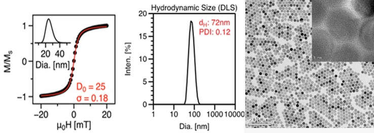
VSM magnetization curve, DLS plot, and TEM image of nanoparticles (LS-1) showing monodisperse size distribution.
FIG. 2.
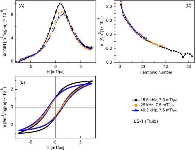
MPS signal parameters of the LS-1 (fluid) sample at various slew rates (field = 7.5 mT/μ0): (a) dm/dH, (b) m(H) curves, (c) Signal harmonics.
Figure 2 shows the tracer's response as fluid nanoparticles at different slew rates, where the frequencies were varied but amplitude was fixed at 7.5 mT/μ0. By convention, only half of the full period (forward scan) is shown in all plots of m′(H). Peak intensity of m′(H) was highest at 15.5 kHz and it decreased slightly as the frequency was increased. Coercive force increased with increasing frequency. The relative intensity of detected harmonics was similar for each drive field condition, although fewer harmonics were detected as the drive field frequency increased, due to the fixed sampling rate of 2 × 10⁶ samples per second. Fluid nanoparticles showed greater dm/dH peak intensity than the immobilized particles (by 16%, 12%, and 3%, respectively) (not shown).
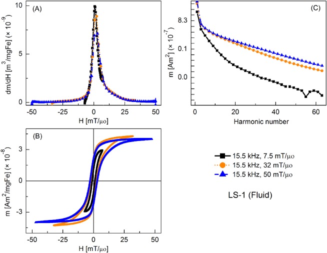
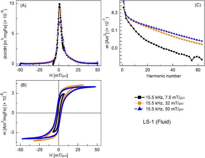
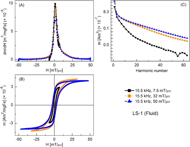
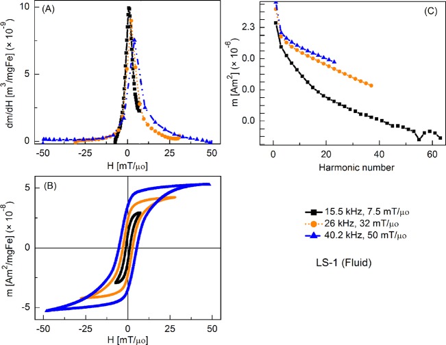
Figure 3 shows the MPI tracer response as fluid nanoparticles at different slew rates, with frequency kept constant at 15.5 kHz and the field amplitude varied from 7.5 to 50 mT/μ0. Peak dm/dH was greatest for the smallest field amplitude and it decreased with increasing field. There was a similar trend for the coercive force. A significant increase in higher harmonic intensity was observed with increasing drive field amplitude. Fluid nanoparticles showed greater dm/dH peak intensity (by 16%, 20%, and 2%, respectively) than the immobilized particles (not shown).
FIG. 3.
MPS signal parameters of LS-1 sample at various slew rates (frequency = 15.5 kHz): (a) dm/dH, (b) m(H) curves, (c) Signal harmonics.
Figures 4 and 5 show the MPS signal of fluid and immobilized nanoparticles for three combinations of field amplitudes and frequencies that produced identical slew rates. The tracer response was almost the same for each of the three combinations and so was the coercive force. Hysteresis curves had the same patterns except that smaller field amplitudes were insufficient to saturate the tracer's magnetization thus giving minor loops. Harmonic intensity was very sensitive to the field amplitude; smaller amplitudes invariably led to a reduced harmonic intensity at higher harmonics. Fluid nanoparticles showed greater dm/dH peak intensity than the immobilized particles.
FIG. 4.
MPS signal parameters of the LS-1 sample at a constant slew rate (5050 T/μ0/s): (a) dm/dH, (b) m(H) curves, (c) Signal harmonics.
FIG. 5.
MPS signal parameters of the LS-1-3 (frozen) sample at a constant slew rate (4870 T/μ0/s): (a) dm/dH, (b) m(H) curves, (c) Signal harmonics.
Figure 6 shows the MPS signal parameters of the fluid nanoparticles over a wider range of slew rates caused by varying both the frequency and amplitude of the drive field. Slew rate dependence of MPI tracer response is quite evident: for the lowest slew rate, there was a minor loop with the maximum susceptibility (at the coercive field), which gives highest intensity MPS signal. At higher slew rates, the coercive field increased and susceptibility (at coercive field) decreased, reducing slightly the MPS signal. Harmonic intensity again increased significantly with increased drive field amplitude. Fluid nanoparticles show greater dm/dH peak intensity (by 16%, 23%, and 16%, respectively) than the immobilized particles (not shown).
FIG. 6.
MPS signal parameters of the LS-1 sample at different slew rates: (a) dm/dH, (b) m(H) curves, (c) Signal harmonics.
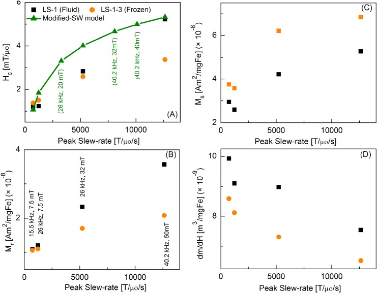
Figure 7 shows a comparison of the MPS signal parameters over a wider range of peak slew-rates for fluid and immobilized nanoparticles. Coercive force, Hc, increases with the slew rate, and it is in agreement with the theoretical values calculated using a modified Stoner-Wohlfarth (SW) model.7 Remanence magnetization, Mr, and saturation magnetization, Ms, also increase with the slew rate. However, dm/dH peak signal intensity decreases with increasing peak slew rate. All these parameters had higher values for the fluid sample when compared to the immobilized sample, except Ms that showed opposite trend.
FIG. 7.
Peak Slew-rate dependence of magnetic parameters of LS-1 (fluid) and LS-1-3 (frozen) particles: (a) Coercive force Hc, (Modified-SW model calculations were performed using Eq. (6)), (b) Remanence magnetization Mr, (c) Saturation magnetization Ms, (d) dm/dH.
IV. DISCUSSION
The magnetically optimized, monodisperse tracer samples used in this study showed highly non-linear behavior, producing a sharp tracer response and ample higher harmonics useful for MPI. With uniformly sized magnetic cores and well-defined hydrodynamic size, the samples are also ideal for studies of how tracer behavior responds to variations in the drive field, since variations in response can be assumed to come from uniform changes in the response of each particle, rather than from multiple fractions of varying size, as in clustered-core particles like ResovistTM.
Previous theoretical7,18 and experimental12,19 studies demonstrated that magnetic nanoparticle magnetization depends on the applied field conditions. Here, we provide the first thorough experimental investigation of slew-rate dependent magnetization behavior using ideal samples. A few observations summarize how the tracer response varied with different drive field conditions:
-
(1)
The magnetic behavior of the sample varied with the peak slew-rate, including the tracer response (dm/dH) and coercive field, Hc. The variations can be explained using modified Stoner-Wohlfarth based theories of coherent rotation including thermal fluctuations.
-
(2)
The dm/dH response varied notably with field amplitude. As expected, small-amplitude excitations did not saturate the tracer magnetization and produced a “minor loop.” Minor loops also typically showed a reduced coercivity. Harmonic intensity decreased with field amplitude, since low-amplitude excitations probed only the linear region of the particle magnetization.
-
(3)
Significant variations in magnetic behavior were observed between fluid and immobilized (frozen in DMSO) samples, with fluid nanoparticles showing higher dm/dH than immobilized particles. However, both fluid and immobilized samples showed slew-rate dependent magnetic behavior.
A. Slew-rate dependence
In this study, we used MPS to obtain dm/dH data and, by integration, m(H) (AC hysteresis) data for various drive field conditions. When the drive field conditions were changed but the peak slew-rate held constant, as in Fig. 4, the MPI tracer's dm/dH response remained mostly unchanged. This was also observed for the DMSO-immobilized tracers (Figure 5). Some minor differences were observed, and these may potentially be attributed to under-sampling of the signal at high slew rates, due to the maximum 2 MS/s acquisition rate of our hardware. On the other hand, when the peak slew-rate was varied, the magnetic response changed (Figure 6 shows greatest range of slew rates, Figures 2–5 show smaller ranges). We interpret these results by considering the competition between thermal energy, magnetic order, and the strong oscillating drive field over the nanoparticle magnetization orientation. In practice, this leads to a dependence of the magnetic properties, such as coercive field, on the slew rate. In AC hysteresis measurements (high slew rate), the samples showed significant coercive field and remanence. On the other hand, the same samples displayed superparamagnetic behavior, with no remanent magnetization, in magnetization curves measured by VSM (very low slew rate) (Figure 1). Superparamagnetism, which affects small ferromagnetic particles, is the randomization of the magnetic moment that occurs in the absence of an applied field, when thermal energy exceeds the energy barrier between low energy states that is established by magnetic anisotropy in the particle. The critical size for superparamagnetism is defined for a measurement time, τmeas, typically 100 s (Ref. 15) (The critical diameter for magnetite is ∼28 nm). The Néel relaxation time, τN, describes reversal of the magnetic moment vector within the magnetic crystal itself, without any physical motion of the particle. Critically, the Néel relaxation mechanism is magnetic field-dependent. In a strong field, such as in the MPS experiments described herein, it is energetically favorable for the moment to align with the field, increasing the probability of thermal hopping from the antiparallel to parallel alignment. To first approximation, the field dependent Néel relaxation time can be written15
| (5) |
with K, the magnetocrystalline anisotropy constant [J/m3], V, the magnetic volume, kB, Boltzmann's constant (1.38 × 10⁻²³ J/K), and τo, the attempt time (typically 10−9 s). For particles in solution, magnetic relaxation can also occur by physical rotation of the particles, called Brownian relaxation. For weak applied fields, the faster of the two relaxation times dominates.
The relaxation described in (5) provides a simple and intuitive physical model; however, it is insufficient to predict ferrofluid magnetization in the strong, continuously varying applied field used in MPI (and MPS), where the relaxation time also varies continuously. Complete description requires more sophisticated numerical models,18 for example, those that integrate thermal fluctuations into the Stoner-Wohlfarth theory of coherent rotation,20 which are beyond the scope of this work. Carrey, Mehdaoui, and Respaud7 derived, from such a model,20 a simple relationship between coercive field, HC, and time-varying applied field,7 that we use to interpret AC hysteresis measurements. Thermal fluctuations effectively reduce the coercivity, Hc. Coercivity also depends on the driving field amplitude and frequency (i.e., slew rate). For a random orientation of particles, the coercive field is given by7
| (6) |
where
| (7) |
with Hk (0.03 T/μ0) the field at which the energy barrier due to general uniaxial anisotropy is suppressed (equal to 2Keff/μ0Ms) for magnetocrystalline anisotropy, Keff (5 kJ/m3) is the effective uniaxial anisotropy, determined from previously published magneto-relaxometry, AC susceptibility, and MPS studies,21 and V is the particle volume (8.18 × 10⁻²⁴ m3). According to Usov et al.,7,20 b = 0.9, n = 1. We note that according to Carrey et al.,7 Eq. (6) is valid when κ < 0.5, yet for our samples the calculated values of κ were slightly higher (0.5 < κ < 0.8). As a result, Eq. (6) likely overestimates the coercivity that would be calculated for our sample by the numerical model presented in Usov et al.20 Nonetheless, given that there are no better simple models, and that implementation of a more sophisticated numerical model is the subject of future work, we use Eq. (6) to illustrate that the increase in Hc we observed with slew rate in our data are in reasonable agreement with this model.
It is important to note that the applied field ramping rate influences the coercivity: when more time is permitted for thermal hopping over the barrier, i.e., for slower ramping rates, the coercivity is reduced, while for faster ramping rates, the coercivity is greater. Theoretical coercivities were calculated using the above equations (6) and (7), and compared with our experimental data. Figure 7(a) shows calculated and measured coercivities, showing agreement. For higher slew rates, HC increased due to the nanoparticles dynamics predicted by Eq. (7). The loop area also increased with slew rate, and the maximum dm/dH decreased and shifted to higher fields.
Previously, our group (Arami, et al.12) reported MPS tracer response of 22 nm core diameter particles subjected to excitation fields of 26 kHz, having amplitudes 5–20 mT/μ0. Later on, Tomitaka, et al.19 reported 26 nm magnetic cores driven by fields of 26 kHz having amplitudes 5–40 mT/μ0. Both findings showed slew-rate dependent behavior that was in contradiction to predictions of the modified Stoner-Wohlfarth model described in (6) and (7) and thus not in agreement with this set of data. The disagreement between those studies and this one highlights the challenge of preparing suitable magnetic nanoparticle tracers. The quality of samples used here reflects further advances in synthetic procedures to produce more uniform core and hydrodynamic size. In the previous studies, response from the multiple fractions of varying sizes may have obscured the relatively small changes caused by slew rate that we observed here.
B. Amplitude dependence
We also observed strong dependence of magnetic behavior on field amplitude. Small field amplitudes produced minor loops, which also featured slightly increased susceptibility (at the coercive field) with reduced coercivity and remanence. Harmonic intensity was strongly correlated to field amplitude, with small amplitudes showing significantly reduced harmonics. This is to be expected, since the small field amplitude probes only the most linear portion of the magnetization response. It is also important to note that field amplitude determines the field of view (FOV) for MPI imaging; for small amplitude drive fields, multiple FOVs must be stitched together to cover the same volume covered by a larger amplitude drive fields. More information was encoded in the harmonic spectrum as the field amplitude was increased.
C. Fluid versus immobilized samples
Finally, we observed significant variation in response between immobilized (frozen in DMSO) and liquid samples. Fluid nanoparticles demonstrated both Néel and Brownian relaxations, though the Néel mechanism dominated, indicated by the relatively small decrease in peak dm/dH generated by immobilized particles with restricted Brownian rotation. However, the observed difference between fluid and immobilized samples does indicate that some Brownian rotation plays a role in MPS experiments, perhaps by permitting alignment of individual particles or even chaining or clustering. Further work is in progress to better characterize these variations.
Field amplitudes of less than 20 mT/μ0 will likely be necessary to avoid patient heating and nerve stimulation for human MPI. Our results show that optimized MPI tracers, such as the one studied here, will perform better at lower drive field amplitudes if the frequency is held constant at 26 kHz, and show equivalent performance if the frequency is proportionally increased to compensate for the reduced field of view at low field amplitude. The compromise of low field amplitude and high frequency can be a favorable combination to yield good MPI performance with reasonable scan times.
V. CONCLUSION
MPI tracers showed peak slew-rate dependent performance at various combinations of drive field amplitudes and frequencies. We studied the behavior of a well-optimized, monodisperse MPI tracer sample under multiple amplitudes ranging from 7 to 52 mT/μ0 and frequencies at 15.5, 26, and 40.2 kHz. We compared fluid and immobilized nanoparticles data and found that the magnetization response was mainly due to Néel relaxation compared to the Brownian relaxation. The response varied notably with field amplitude; in particular, small-amplitude excitations did not saturate the tracer magnetization and produced “minor loops.” For higher peak slew-rates, m(H) loops got wider due to the nanoparticles dynamics. The increasing drive field frequency caused a phase lag in the switching of moments with the oscillating field, and the higher field amplitude increased the field of view by saturating the magnetization. When the drive field conditions were changed but the peak slew-rate held constant, the dm/dH response of the MPI tracer was almost the same, even for the immobilized nanoparticles. Our experimental results were in reasonable agreement with a modified Stoner-Wohlfarth model of slew-rate dependent magnetic reversal. We expect that low drive-field amplitude in combination with high frequency will provide a good compromise between patient safety, scanning time, and tracer performance.
ACKNOWLEDGMENTS
This work was supported by NIH Grant Nos. 2R42EB013520-02A1, a UW/CGF commercialization Grant and a Commercialization Fellowship (R.M.F.). Dr. Saqlain Shah is grateful to Higher Education Commission (HEC), Government of Pakistan, for financial assistance.
References
- 1.Ferguson R. M., Minard K. R., and Krishnan K. M., J. Magn. Magn. Mater. 321, 1548 (2009). 10.1016/j.jmmm.2009.02.083 [DOI] [PMC free article] [PubMed] [Google Scholar]
- 2.Krishnan K. M., IEEE Trans. Magn. 46, 2523 (2010). 10.1109/TMAG.2010.2046907 [DOI] [PMC free article] [PubMed] [Google Scholar]
- 3.Reilly J. P., IEEE Trans. Biomed. Eng. 45, 137 (1998). 10.1109/10.650371 [DOI] [PubMed] [Google Scholar]
- 4.Bottomley P. A. and Edelstein W. A., Med. Phys. 8, 510 (1981). 10.1118/1.595000 [DOI] [PubMed] [Google Scholar]
- 5.Saritas E. U., Goodwill P. W., Zhang G. Z., and Conolly S. M., IEEE Trans. Med. Imaging 32, 1600 (2013). 10.1109/TMI.2013.2260764 [DOI] [PubMed] [Google Scholar]
- 6.Ferguson R. M., Khandhar A. P., and Krishnan K. M., J. Appl. Phys. 111, 07B318 (2012). 10.1063/1.3676053 [DOI] [PMC free article] [PubMed] [Google Scholar]
- 7.Carrey J., Mehdaoui B., and Respaud M., J. Appl. Phys. 109, 083921 (2011). 10.1063/1.3551582 [DOI] [Google Scholar]
- 8.Khandhar A. P., Ferguson R. M., Simon J. A., and Krishnan K. M., J. Biomed. Mater. Res. A 100A, 728 (2012). 10.1002/jbm.a.34011 [DOI] [PMC free article] [PubMed] [Google Scholar]
- 9.Jana N. R., Chen Y., and Peng X., Chem. Mater. 16, 3931 (2004). 10.1021/cm049221k [DOI] [Google Scholar]
- 10.Kalele S., Narain R., and Krishnan K. M., J. Magn. Magn. Mater. 321, 1377 (2009). 10.1016/j.jmmm.2009.02.134 [DOI] [Google Scholar]
- 11.Narain R., Gonzales M., Hoffman A. S., Stayton P. S., and Krishnan K. M., Langmuir 23, 6299 (2007). 10.1021/la700268g [DOI] [PubMed] [Google Scholar]
- 12.Arami H., Ferguson R. M., Khandhar A. P., and Krishnan K. M., Med. Phys. 40, 071904 (2013). 10.1118/1.4810962 [DOI] [PMC free article] [PubMed] [Google Scholar]
- 13.Goodwill P. W. and Conolly S. M., IEEE Trans. Med. Imaging 29, 1851 (2010). 10.1109/TMI.2010.2052284 [DOI] [PubMed] [Google Scholar]
- 14.Schmale I., Rahmer J., Gleich B., Borgert J., and Weizenecker J., in Magn. Part. Imaging, edited by Buzug T. M. and Borgert J. ( Springer Berlin, Heidelberg, 2012), pp. 287–292. [Google Scholar]
- 15.Ferguson R. M., Khandhar A. P., Arami H., Hua L., Hovorka O., and Krishnan K. M., Biomed. Tech. 58, 493 (2013). 10.1515/bmt-2012-0058 [DOI] [PMC free article] [PubMed] [Google Scholar]
- 16.Goodwill P. W., Tamrazian A., Croft L. R., Lu C. D., Johnson E. M., Pidaparthi R., Ferguson R. M., Khandhar A. P., Krishnan K. M., and Conolly S. M., Appl. Phys. Lett. 98, 262502 (2011). 10.1063/1.3604009 [DOI] [Google Scholar]
- 17.Chantrell R. W., Popplewell J., and Charles S., IEEE Trans. Magn. 14, 975 (1978). 10.1109/TMAG.1978.1059918 [DOI] [Google Scholar]
- 18.Weizenecker J., Gleich B., Rahmer J., and Borgert J., Phys. Med. Biol. 57, 7317 (2012). 10.1088/0031-9155/57/22/7317 [DOI] [PubMed] [Google Scholar]
- 19.Tomitaka A., Ferguson R. M., and Krishnan K. M., IWMPI Proceedings, 2014. [Google Scholar]
- 20.Usov N. A. and Grebenshchikov Y. B., J. Appl. Phys. 106, 023917 (2009). 10.1063/1.3173280 [DOI] [Google Scholar]
- 21.Ludwig F., Remmer H., Kuhlmann C., Wawrzik T., Arami H., Ferguson R. M., and Krishnan K. M., J. Magn. Magn. Mater. 360, 169 (2014). 10.1016/j.jmmm.2014.02.020 [DOI] [PMC free article] [PubMed] [Google Scholar]


