The field of image-guided interventional therapies is rapidly growing, both in technical development and clinical adoption. Such interventions are increasingly being used to treat many types of cancer [1]. Most cancerous tumors are now diagnosed with computed tomography (CT), magnetic resonance imaging (MRI), or ultrasound imaging. After diagnosis, surgical removal continues to be the preferred treatment for most focal tumors. However, open surgery is traumatic. It often requires general anesthesia, several days of hospital recovery, and weeks of outpatient recovery and rehabilitation before the patient can resume normal daily functions. For millions of cancer patients every year, the medical risks of surgical tumor removal do not outweigh the potential benefits conferred. In addition, the significant financial cost of surgery has put pressure on the health-care system to find alternative treatments that are less expensive but equally as effective. This is not a novel problem: a popular aphorism from Hippocrates can be translated as “those diseases which medicines do not cure, iron cures; those which iron cannot cure, fire cures; and those which fire cannot cure, are to be reckoned wholly incurable.” Thermal tumor ablation is an extension of this concept in modern form.
A Minimally Invasive Treatment Option for Cancers
Definition
Thermal ablation refers to the destruction of tissue by extreme hyperthermia or hypothermia.
Thermal ablation refers to the destruction of tissue by extreme hyperthermia (elevated tissue temperatures) or hypothermia (depressed tissue temperatures). The temperature change is concentrated to a focal zone in and around the tumor. The overall objective of thermal tumor ablation is quite similar to that of surgery: remove the tumor and a 5–10-mm thick margin of seemingly normal tissue. Surgical removal consists of physical excision; during thermal ablation, the tissue is killed in situ and then absorbed by the body over the course of several months. Like surgery, thermal ablation can be performed using an open, laparoscopic, or endoscopic approach; however, it is most commonly applied using a percutaneous or noninvasive approach (Figure 1). The choice of approach often depends on the type of tumor, its anatomic location, physician’s preference, as well as the underlying health of the patient.
FIGURE 1.
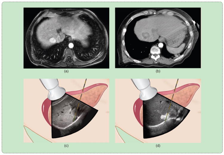
A percutaneous thermal ablation procedure. The tumor is identified, and the applicator is inserted using imaging guidance. An ablation zone is created to cover the entire tumor with margins and then verified using follow-up imaging. (a) Diagnosis. (b) Follow-up. (c) Preablation. (d) Postablation.
Although a surgical procedure is performed by visual inspection with histopathological assessment of the excised tumor and margins, percutaneous and noninvasive thermal ablation is performed strictly with the aid of imaging. Applicator guidance into the target zone, treatment monitoring and verification, and clinical follow-up rely on effective imaging. Detailed discussion of imaging is beyond the scope of this article, but the influence of imaging on the choice of thermal ablation or procedural approach will be discussed as needed. More information on imaging for interventional therapies can be found in other articles in this issue of IEEE Pulse.
Clinical Indications
The most common anatomic site for thermal ablation is the liver.
The most common anatomic site for thermal ablation is the liver. Primary cancers arising in the liver are the seventh leading cause of cancer worldwide, accounting for more than 750,000 new cancer cases and 700,000 deaths each year [2]. The most significant risk factor for liver cancer is cirrhosis, usually associated with chronic infections of hepatitis B or C viruses, alcoholism, or long-term fatty liver disease [3]. The liver is also a common site of metastatic tumors from different organs because of the large blood flow and filtering function of the liver. In addition, benign hepatic tumors and cysts can become symptomatic enough to require intervention. Surgery or transplantation is the preferred treatment for hepatic tumors, but up to 80% of liver cancer patients are not eligible for surgery because of poor baseline health, risk of excessive bleeding due to poor blood clotting, or lack of sufficient liver function reserve [4]. Radiation is particularly hard on normal liver cells, and chemotherapy has not shown a long-term benefit against primary liver cancer. Therefore, there is a strong need for effective alternative treatments for tumors in the liver.
As clinical data begin to support its use against liver tumors, interest in thermal ablation is growing for the treatment of other cancers. Thermal ablation has effectively replaced surgery as the treatment of choice for benign osteoid osteomas, especially in pediatric patients [5]. A large proportion of primary kidney tumors are now being treated with thermal ablation, with many centers considering ablation as a possible first-line option [6]. Thermal ablation is also being investigated for inoperable pulmonary nodules and breast tumors, but the availability of traditional therapies in these organs has inhibited wider clinical adoption to date. There may also be a role for thermal ablation in the treatment of tumors in the neck, adrenal glands, and pancreas, as well as cystic tumors and endocrine tumors that can present a problem for traditional treatments. Clinical adoption in these areas will depend on long-term results in ongoing pilot studies.
Thermal Ablation Biophysics
Either hot (hyperthermic) or cold (hypothermic) temperatures can produce cellular necrosis.
As mentioned earlier, either hot (hyperthermic) or cold (hypothermic) temperatures can produce cellular necrosis. Cells in the human body can withstand a wide variety of temperatures, and some cells are more thermotolerant than others. The probability of death is related to the thermal history or thermal dose of each particular cell [7], [8]. As a general rule, complete necrosis occurs almost instantaneously at temperatures below −40 °C or in excess of 60 °C for most cell types [9]. Less extreme temperatures require longer exposure times, with temperatures between 5 and 41 °C providing no long-term therapeutic benefit.
Thermal ablation is a transient heat-transfer problem and is thus most commonly described using Penne’s formulation of the Fourier heat equation:
| (1) |
where ρ is the tissue density (kg/m3), Cp is the specific heat capacity (J/kg · K), T is the temperature (K), t is the time (s), k is the thermal conductivity (W/m · K), Qh is the heat flux of the ablation source, Qm is the metabolic heat flux, and Qp is the blood perfusion heat flux. In most cases, metabolic heat generation is much slower than either the perfusion or source terms, so can be ignored. There are other models that account for microvascular blood flow and heat transfer differently, but because of the high temperatures and rapid heating rates associated with thermal ablation, the formulation above is most common.
The presence of large or high–low blood vessels in the target area creates a substantial source (or sink) of thermal energy (Figure 2). Vessels smaller than about 3 mm typically are not problematic, but larger vessels may buffer adjacent cells from the intended thermal damage [10], [11]. As a result, large vessels have been linked to increased local recurrence rates [12]. Therefore, the goal of thermal ablation systems is to overcome local perfusion or vascular heat sinks by more intense heating or cooling—i.e., to create a larger difference between Qh and Qp.
FIGURE 2.
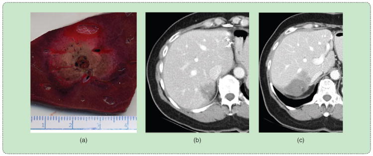
Effect of vessels on the ablation zone. (a) A high-flow vessel indents the ablation zone from the expected circular cross-sectional shape. (b) The presence of a large vessel near the tumor creates a high probability of local recurrence, (c) as observed in the three-month follow-up exam.
Hyperthermic Ablation
Elevated temperatures affect cells in a variety of ways, but the primary means of cell death during thermal tumor ablation is acute coagulative necrosis. Temperatures up to 41 °C cause blood vessel dilation and increased blood perfusion and trigger a heat-shock response that aims to protect the cell from thermal injury and repair any damage incurred [9]. These temperatures have little long-term effect even when maintained for hours. Up to 46 °C, irreversible cell damage begins to occur. The heat-shock response is intensified, but exposures up to 10 min will lead to necrosis of a significant population of the cells. Those that recover may exhibit an increased tolerance to elevated temperatures. Temperatures of 46–52 °C reduce the time needed to achieve cell death and also begin to cause microvascular thrombosis, ischemia, and hypoxia. This cascade cuts off the cells’ nutrient supply and leads to delayed necrosis. Temperatures in excess of 60 °C cause rapid protein denaturation and melt the plasma membrane that allows the cells to survive.
Further rises in temperature are associated with physical changes such as water vaporization, desiccation, and carbonization. These changes in physical properties do not enhance cell death directly but do influence the delivery of energy from the ablation device. In particular, water vaporization and tissue charring cause a precipitous drop in 1) tissue conductivity, which impedes radio-frequency (RF) power delivery; 2) complex permittivity, which alters microwave antenna performance and power delivery; 3) optical transmission, which irreversibly prohibits laser light penetration; and 4) ultrasound transmission. In each case, the therapeutic heating process itself alters future energy delivery. All systems must account for these changes to maximize efficacy.
Technologies Overview
RF electrical current, microwave radiation, laser light, and ultrasound acoustic waves are the most common sources of clinical hyperthermic tumor ablation. With the exception of noninvasive high-intensity focused ultrasound (HIFU), these energies are applied using interstitial devices that are essentially needlelike in form. Clinical systems consist of two main systems: a source of either heating or cooling and a delivery system. For surgical or percutaneous approaches, the delivery system consists of an applicator that is inserted into the tumor and a method for coupling the applicator to the source (Figure 3). Since percutaneous thermal ablation procedures are performed by radiologists accustomed to image-guided biopsy, most ablation devices have a needlelike form similar to biopsy devices. Percutaneous ablation devices are less than 2.5 mm in diameter to reduce complications associated with larger, more traumatic devices [13].
FIGURE 3.
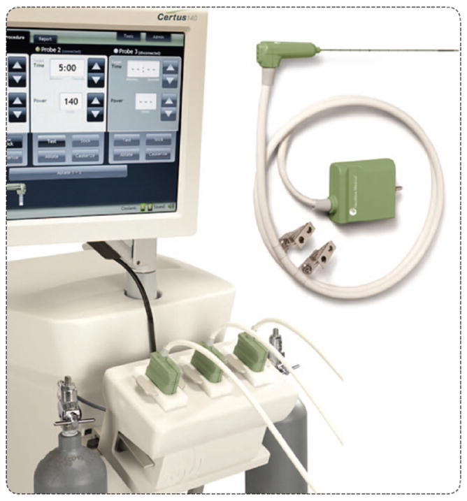
A microwave ablation system illustrates the main components of most ablation systems: a generator with some type of user interface or control, a power distribution system, and a delivery device that is applied directly to the tumor. (Image courtesy of NeuWave Medical, Inc.)
When possible, solitary tumors are treated using a single applicator. However, depending on the size, shape, and location of the tumor, such an approach is neither always feasible nor optimal.
MRI can be used to precisely measure temperature and thermal dose.
Historically, tumors too large to be treated with a single applicator placement required multiple overlapping ablations to cover the tumor volume completely [14]. This procedure is fraught with challenges, including visualization of the residual tumor after each subsequent treatment on imaging and the potential for complications or tumor seeding due to applicator repositioning. Multiple devices can also be used in concert to exploit synergistic interactions between the growing ablation zones [15]-[17]. Recent studies have proven the benefits of using multiple applicators simultaneously: larger ablation zones, improved confluence and homogeneity of temperatures in the ablation zone, and more rapid placement of each applicator due to clear imaging visibility and the ability to use previous applicators as a guide for subsequent placements [18]-[20]. The drawback to this approach is that placing multiple devices increases procedural trauma and financial expense.
Radio Frequency Ablation
RF ablation evolved from electrocautery in the 1990s and has become the most widely used ablation modality worldwide. During RF ablation, electrical current is applied directly to the target zone; however, at least two electrodes are required to complete an electrical circuit through the body. The typical approach is to insert one electrode into the body (interstitial electrode) with a second electrode fixed to the skin surface (dispersive electrode or grounding pad). Since only one electrode is applied to the tumor, this setup is referred to as unipolar. Bipolar operation implies that current oscillates between two interstitial electrodes applied to the tumor (Figure 4).
FIGURE 4.
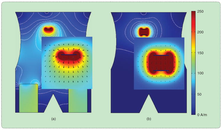
(a) Unipolar and (b) bipolar RF ablation in a simulated abdomen. Electrical current oscillates between one or more electrodes applied directly to the tumor. Heat generation is proportional to current density, which is greatest near the interstitial electrodes but can cause skin burns near improperly placed surface electrodes.
Modern RF ablation systems are capable of generating up to 250-W power output or about 2.3 A of current in a typical 50-W tissue load. The RF generator operates primarily as a voltage source, so the average power delivered can be calculated from Ohm’s law: P = V2/Z, where Z is the impedance of the circuit, which is determined by the surface area of the electrode–tissue boundary and the types of tissue involved in the current path. For example, liver is relatively conductive because of its high water and ion content, so creates a low-impedance electrical current path. Conversely, aerated lung and fat have lower water and ion contents, so are associated with much higher electrical impedance. This makes RF ablation challenging in lung since even electrically conductive tumors are surrounded by lung parenchyma. In addition, tissue heated to ablative temperatures, especially those near 100 °C, experience rapid dehydration as water is boiled to water vapor. This sudden decrease in tissue water content leads to a spike in the circuit impedance and a corresponding drop in applied power. Therefore, the ablative heating process itself is a limitation for RF ablation. The mechanism of heating in RF ablation is oscillation of ions primarily in the extracellular fluid space, leading to Joule or resistive heat generation. The heating term from (1) is:
| (2) |
where J is the current density (A/m), E is the electric field intensity (V/m), and σ is the electrical conductivity (S/m). This relationship illustrates the fact that RF heating is proportional to the square of current density.
RF electrodes are designed to create zones of high current density that are large enough to cover the tumor plus an ablative margin. Early electrodes consisted of simple bare wires, but heating with this design was easily subverted by water vaporization and tissue dehydration. A work-around is to cool in the interior of the electrode itself to reduce temperatures at the electrode–tissue interface [21]. This solution works best when combined with power pulsing. That is, when the circuit impedance begins to spike, RF power is suspended for several seconds to allow the tissue temperatures to equilibrate and water vapor around the electrode to condense. The resulting increase in tissue conductivity allows greater RF power to be applied during the next heating cycle. Since thermal conduction through the tissue is much slower than RF heating itself, turning the power off does not detract ablation zone growth. In fact, the combination of electrode cooling and pulsed power creates larger ablation zones than either solution alone [22].
Most cancerous tumors are diagnosed with computed tomography, MRI, or ultrasound imaging.
Another solution to increase RF ablation zone size is to spatially distribute the power throughout the tumor volume, either by using multiple needle electrodes or electrodes with deployable tines (Figure 5) [23]-[25]. The former solution requires insertion and guidance of up to three electrodes. The electrodes may be operated in parallel, as a bipolar array, or by sequential switching to improve heating uniformity within the target zone. The latter requires the placement of only one device, with the umbrella or star-shaped array of deployed tines providing the necessary distribution of electrical current. These deployable electrodes are larger in diameter than cooled electrodes (2.4-mm versus 1.5-mm diameter), and the tines can be difficult to advance into many tumors. Both multiple-electrode and deployable techniques have been shown to increase the size of RF ablations.
FIGURE 5.
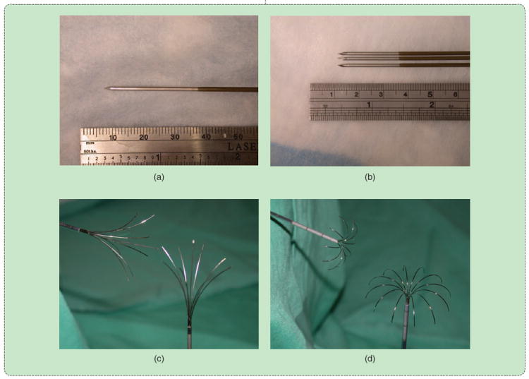
RF ablation electrodes in common clinical use: (a) unipolar water-cooled single and (b) cluster and deployable arrays with (c) star and (d) umbrella shapes. (Reprinted with permission from [1].)
It is also possible to augment the electrical conductivity of the surrounding tissue medium by infusing an ionic fluid such as saline. This technique can be beneficial to cool the tissue around the electrode and counteract the low conductivity of dehydrated or charred tissue [26]. This is particularly useful during bipolar RF ablation, since the electrode–tissue interface and current path is relatively small compared with unipolar ablation with dispersive electrodes. Saline infusion is not widely used, however, because the distribution of saline can be unpredictable and inhomogenous. Some reports have shown that the saline can migrate in the body cavity and causes severe heating distant from the intended treatment zone [27].
Overall, RF ablation has found the greatest utility in treating small tumors (up to 3-cm diameter) in the liver and kidney as well as benign bone tumors. The use of deployable devices or multiple-electrode systems has increased the efficacy of RF ablation for medium tumors (up to 5-cm diameter) and improved RF energy delivery in the lung. However, RF ablation still suffers from the problem of relatively slow heat generation. A possible solution is to use higher generator powers (up to 1,000 W), but such a system has not yet been clinically deployed [28], [29]. Even with higher powers, RF is limited by the reliance on electrical current conduction. High-impedance tissues, including the RF ablation zone itself, preclude effective RF ablation when the applied power is limited. Therefore, investigations have lately been focused on alternatives to RF for thermal tumor ablation.
Microwave Ablation
Microwave tissue heating has been explored in many forms since the 1970s, primarily for externally applied low-temperature hyperthermia. The widespread utilization of microwaves for thermal tumor ablation is more recent. As with RF ablation, microwave energy is delivered into the tumor using a needlelike applicator. However, microwaves radiate from an interstitial antenna. Since radiation occurs by virtue of the antenna geometry, no ground pads are required, and the drawbacks associated with electrical current conduction are minimized. In particular, microwave energy will propagate through all types of tissue, including water vapor and dehydrated or desiccated tissue inside of ablation zones. Heat is generated primarily by electromagnetic interaction with polar molecules such as water. Similar to RF ablation, the heat generation term from (1) is
where σ is now the effective conductivity, which accounts for effective and displacement currents. It is important to remember that while low-conductivity tissues will generate less heat than a higher conductivity tissue under the same applied field, energy will propagate through those tissues with less attenuation; propagation and attenuation are inversely related.
The microwave power source may be either based on solid-state or vacuum devices, and power is distributed via coaxial cables to the applicator antenna [30]. The antenna can be further subdivided into handle, shaft, and radiating sections. The radiating section has received the most attention in the literature, with dozens of designs having been described [31], [32]. All antenna designs aim to achieve the same two goals: 1) efficient radiation into the surrounding tissue to maximize energy delivery and 2) control of the radiation pattern to produce the desired ablation zone geometry. In many cases, a spherical heating geometry is desirable to match the shape of most tumors targeted by thermal ablation, but more elongated shapes can be advantageous when using arrays of interstitial antennas or when treating tumors surgically.
One of the early difficulties with microwave ablation was the inability to control heating along the proximal portion of the antenna, resulting in teardrop-shaped ablation zones. Similarly, the small-diameter coaxial cables that comprise the antenna can overheat and fail when delivering high microwave powers (> ~30 W). Overheating cables lead to excessive temperatures along the antenna shaft and potentially dangerous complications such as fistulas. Larger cables (>3-mm diameter) that handle high powers without overheating are not suited for percutaneous application. One solution to this problem is to limit the power and time applied by the antenna. Early clinical studies that used this technique were able to mitigate complications, but with predictable limitations on ablation size and efficacy for common tumors. A more recent solution is to cool the antenna using either water or cryogenic gas expansion. With effective cooling, it is now possible to deliver more than 200 W of power through antennas 1.5 mm in diameter. As a result, microwaves can produce large ablation zones (above 4 cm in diameter) in relatively short amounts of time (10 min or less) (Figure 6).
FIGURE 6.

Microwave ablation created using 140 W at 2.45 GHz for 10 min. The (a) 4.5 × 6.0 cm ablation zone was produced by a 1.5-mm diameter, gas-cooled triaxial antenna in in vivo porcine liver. The same system was used to ablate the 3.2 × 3.4 cm primary liver tumor shown (b) before and (c) after treatment.
In many ways, microwave ablation may be the natural evolution of RF ablation.
In many ways, microwave ablation may be the natural evolution of RF ablation. Since electromagnetic wave propagation is not limited by desiccated tissue, water vapor, or low-water content tissues, microwave ablation may be a more effective modality for tumors in the lung, bone, or cystic lesions. Microwaves also seem able to create larger ablation zones in less time than RF, making them attractive for those procedures for which RF ablation has become more conventional (liver, kidney, and benign tumors of the bone). Health-care economics and long-term clinical data will determine how many centers switch.
Laser Ablation
Lasers have a long and varied history in the medical field and are more commonly associated with eye, skin, vascular, and dental applications than do oncology. However, laser tumor ablation has evolved over the last two decades to become a viable treatment option for many of the same tumors as RF or microwave ablation [16], [33]. Laser light interacts with various tissue components depending on the light wavelength, but most ablation systems target the 800–1,100-nm range to capitalize on deeper energy penetration.
Laser light is very energetic and generates heat rapidly near the applicator. Attenuation can be equally rapid; however, the zone of active heating is approximately 1 cm from the applicator. Even more importantly, as with RF ablation, dehydrated and especially charred tissue increases light attenuation and inhibits energy delivery [34]. Therefore, laser ablation systems employ power control and applicator cooling to prevent charring. There are several laser applicator variants described in the literature, but most systems use a diffusing tip to more isotropically distribute light around the applicator tip [35]. Despite these technical advances, laser ablations from a single applicator are typically not larger than 2 cm in diameter. Larger tumors must be treated with multiple applicators, with some series reporting an average of more than four applicators per treatment [16].
Despite this potential drawback, laser ablation applicators have an additional feature that makes them increasingly interesting: MRI compatibility. The applicators are fabricated from glass optical fibers, allowing them to be used safely in MRI without creating substantial imaging defects. An MRI is important because it can be used to precisely measure temperature and thermal dose [36]. Therefore, laser ablation can be performed in conjunction with MRI thermometry to accurately treat tumors in difficult locations such as the brain and prostate with good confidence about the treatment zone and lack of thermal damage to critical adjacent nervous tissues (Figure 7). Therefore, while laser ablation has only been used by a few centers worldwide to date, its clinical utilization may advance in large academic centers that have interventional MRI or MRI thermometry available.
FIGURE 7.
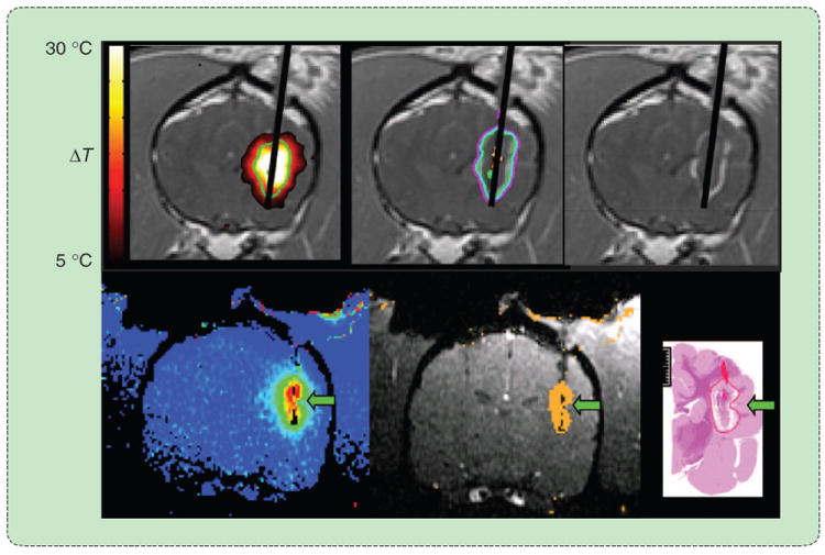
An MRI-guided laser ablation in the brain. The diffusing laser fiber (upper right) is placed transcranially into the tumor using MRI guidance. MR thermometry provides feedback about ablation growth in near real time, allowing accurate control over the treatment zone to avoid peripheral tissue damage. (Images courtesy of Jason Stafford. Reprinted with permission from [33].)
Ultrasound Ablation
Ultrasound energy can be delivered using interstitial devices or external transducers. Interstitial devices are similar to those of other ablation modalities in that they take a needlelike form; however, the applicator typically contains an array of transducers whose wave amplitude and phase can be individually controlled [37], [38]. This permits more control over the heating pattern—axially and longitudinally—than can currently be achieved with other interstitial devices. However, these devices have not yet been made widely available in the marketplace, so clinical data are currently lacking.
Perhaps, the most attractive feature of ultrasound is the ability to ablate tissue noninvasively. HIFU relies on converging ultrasound beams from an external source to produce a focal zone of ultrasound heating [39]. The heating zone is typically about the size of a grain of cooked rice and can be produced in several seconds. An entire treatment is accomplished by overlapping hundreds of these focal zones to cover the tumor volume beginning with the distal aspect (Figure 8). HIFU procedures can take hours to complete and require precise control over the treatment zone over that time. Therefore, HIFU has been applied primarily in areas that are easily accessible and without substantial motion from breathing, such as benign fibroids in the uterus and breast and benign prostate hyperplasia. As the technology of generating and controlling HIFU improves, applications in more difficult locations such as the brain or abdomen may become clinically feasible.
FIGURE 8.
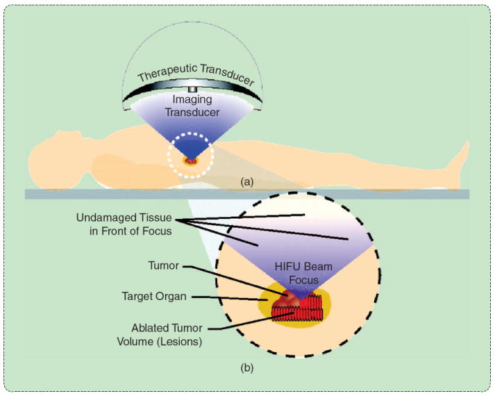
HIFU involves the overlapping of several small focal zones to create a complete treatment. (a) An external transducer is coupled to the skin surface to efficiently apply energy with a converging beam form. (b) When the beam converges, the energy density rapidly increases, leading to small focal zones of thermal damage in the target zone. (Reprinted with permission from [39].)
Laser light is very energetic and generates heat rapidly near the applicator.
Hypothermic Effects
Cryoablation aims to capitalize on all of the detrimental effects many have encountered during cryopreservation [40]. Ice crystal formation, cell membrane rupture, and osmotic imbalances are the primary mechanisms for cell death. Cooling near the cryoablation source (usually a cryoprobe) is rapid enough to cause intracellular ice formation, which mechanically expands the cell membrane beyond repair and almost always kills the cell. Tissues more peripheral to the cryoprobe cool slower. Extracellular ice formation leads to an increase in ion concentration in the remaining extracellular fluid, which causes cellular dehydration as the cell tries to create equilibrium. Continued ice formation creates mechanical stress on the shrunken cell. When the tissue thaws, the osmotic imbalance is typically amplified and leads to cell death. For this reason, most cryoablation procedures incorporate at a succession of freeze–thaw cycles to maximize cell death [41].
Modern cryoablation equipment uses common refrigeration techniques. Most systems continue to use the Joule–Thomson effect with argon as the refrigerant. As the argon gas expands in the tip of the cryoprobe, it creates a negative heat source that cools the adjacent tissue to approximately −160 °C. The rest of the ablation zone grows by thermal conduction, with the lethal isotherm lying 4–10 mm inside of the edge of the visible ice ball (Figure 9). Joule–Thomson systems have been used now for decades to great cancers of the liver, lung, kidney, prostate, breast, and bone, but the ablation zone produced by a given cryoprobe is inversely proportional to its surface area (diameter). In addition, small-diameter cryoprobes produce a weaker heat sink than larger probes because of the smaller pressure drop and limitations on gas flow. Alternative refrigeration techniques include gases held near the critical point. At this point, many materials (such as nitrogen) have a markedly increased heat capacity that creates a greater heat sink. Since the material is at the critical point, it has the viscosity of a gas and is easier to move through small-diameter cryoprobes. However, controlling the gas at the critical point can be technically challenging, so systems with this technology are not yet widely available.
FIGURE 9.
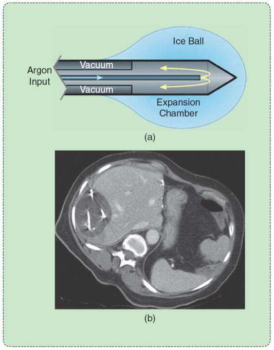
Cryoablation using a Joule–Thomson argon probe. (a) Argon expansion near the probe tip creates (b) an ice ball that is easily visible on CT. The lethal isotherm of approximately −40 °C lies several millimeters inside the ice-ball surface. (Reprinted with permission from [1].)
The main advantages to cryoablation over other thermal ablation modalities are increased visibility on imaging due to ice-ball formation, reliance only on thermal diffusion (rather than energy interaction to produce heat), and less damage to the tissue architecture. The freezing process leaves the collagen structures largely intact, potentially allowing faster and more complete tissue healing [42]. Yet, cryoablation is not indicated for some types of cancer. Cryoablation does not provide a cautery effect, so the rapid introduction of cellular contents into the bloodstream after thawing can lead to a dangerous response known as cryoshock [43]. A similar effect can be noted with neuroendocrine tumors. For this reason, cryoablation is not typically used to treat tumors in patients with cirrhosis or poor clotting factors. In addition, while the ice ball is easily visible, the lethal zone inside that ice ball is not clear on imaging. Finally, gas tanks needed to store the cryogen are not always widely available, and their size can make cryoablation systems more cumbersome than hyperthermic ablation systems. Nevertheless, cryoablation has a prominent role in the thermal ablation armamentarium.
Conclusions
Image-guided thermal tumor ablation continues to make inroads as a viable treatment option for many focal cancers. Ablation methods based on both heat and cold can be used, and there is no single optimal treatment for all clinical presentations. RF ablation has been the dominant energy for hyperthermic ablation to date but may be supplanted by microwave ablation in the coming years. Laser ablation offers MRI compatibility for precise thermal monitoring, while HIFU offers external energy delivery along with MRI compatibility. Cryoablation is used for many of the same tumors and is more visible that hyperthermic ablations on CT and ultrasound but may not be suitable for some cancers because of a lack of coagulation. Despite several years’ worth of clinical experience, most ablation systems are in a first or perhaps second generation of development. As technologies for energy delivering continue to improve, expect to hear more about thermal tumor ablation.
References
- 1.Ahmed M, Brace CL, Lee FT, Jr, Goldberg SN. Principles of and advances in percutaneous ablation. Radiology. 2011 Feb;258(no. 2):351–369. doi: 10.1148/radiol.10081634. [DOI] [PMC free article] [PubMed] [Google Scholar]
- 2.Ferlay J, Shin H, Bray F, Forman D, Mathers C, Parkin D. GLOBOCAN 2008, cancer incidence and mortality worldwide: IARC CancerBase No 10. 2010 [Online]. Available: http://globocan.iarc.fr/
- 3.Bosch FX, Ribes J, Díaz M, Cléries R. Primary liver cancer: Worldwide incidence and trends. Gastroenterology. 2004 Nov;127(no. 5, suppl. 1):S5–S16. doi: 10.1053/j.gastro.2004.09.011. [DOI] [PubMed] [Google Scholar]
- 4.Llovet JM, Bruix J. Systematic review of randomized trials for unresectable hepatocellular carcinoma: Chemoembolization improves survival. Hepatology. 2003 Feb;37(no. 2):429–442. doi: 10.1053/jhep.2003.50047. [DOI] [PubMed] [Google Scholar]
- 5.Rosenthal DI, Hornicek FJ, Torriani M, Gebhardt MC, Mankin HJ. Osteoid osteoma: Percutaneous treatment with radiofrequency energy1. Radiology. 2003 Oct;229(no. 1):171–175. doi: 10.1148/radiol.2291021053. [DOI] [PubMed] [Google Scholar]
- 6.Kunkle DA, Uzzo RG. Cryoablation or radiofrequency ablation of the small renal mass: A meta-analysis. Cancer. 2008 Nov;113(no. 10):2671–2680. doi: 10.1002/cncr.23896. [DOI] [PMC free article] [PubMed] [Google Scholar]
- 7.Sapareto SA, Dewey WC. Thermal dose determination in cancer therapy. Int J Radiat Oncol Biol Phys. 1984 Jun;10(no. 6):787–800. doi: 10.1016/0360-3016(84)90379-1. [DOI] [PubMed] [Google Scholar]
- 8.Henriques FJ. Studies of thermal injury; the predictability and the significance of thermally induced rate processes leading to irreversible epidermal injury. Arch Pathol. 1947 May;43(no. 5):489–502. [PubMed] [Google Scholar]
- 9.Nikfarjam M, Muralidharan V, Christophi C. Mechanisms of focal heat destruction of liver tumors. J Surg Res. 2005 Aug;127(no. 2):208–223. doi: 10.1016/j.jss.2005.02.009. [DOI] [PubMed] [Google Scholar]
- 10.Bhardwaj N, Strickland AD, Ahmad F, Atanesyan L, West K, Lloyd DM. A comparative histological evaluation of the ablations produced by microwave, cryotherapy and radiofrequency in the liver. Pathology. 2009 Feb;41(no. 2):168–172. doi: 10.1080/00313020802579292. [DOI] [PubMed] [Google Scholar]
- 11.Lu DSK, Raman SS, Limanond P, Aziz D, Economou J, Busuttil R, Sayre J. Influence of large peritumoral vessels on outcome of radiofrequency ablation of liver tumors. J Vasc Interv Radiol. 2003;14(no. 10):1267–1274. doi: 10.1097/01.rvi.0000092666.72261.6b. [DOI] [PubMed] [Google Scholar]
- 12.Nakazawa T, Kokubu S, Shibuya A, Ono K, Watanabe M, Hidaka H, Tsuchihashi T, Saigenji K. Radiofrequency ablation of hepatocellular carcinoma: correlation between local tumor progression after ablation and ablative margin. AJR Amer J Roentgenol. 2007 Feb;188(no. 2):480–488. doi: 10.2214/AJR.05.2079. [DOI] [PubMed] [Google Scholar]
- 13.Geraghty PR, Kee ST, McFarlane G, Razavi MK, Sze DY, Dake MD. CT-guided transthoracic needle aspiration biopsy of pulmonary nodules: needle size and pneumothorax rate. Radiology. 2003;229(no. 2):475–481. doi: 10.1148/radiol.2291020499. [DOI] [PubMed] [Google Scholar]
- 14.Dodd GD, III, Frank MS, Aribandi M, Chopra S, Chintapalli KN. Radiofrequency thermal ablation: Computer analysis of the size of the thermal injury created by overlapping ablations. AJR Amer J Roentgenol. 2001;177(no. 4):777–782. doi: 10.2214/ajr.177.4.1770777. [DOI] [PubMed] [Google Scholar]
- 15.Wright AS, Lee FTJ, Mahvi DM. Hepatic microwave ablation with multiple antennae results in synergistically larger zones of coagulation necrosis. Ann Surg Oncol. 2003 Apr;10(no. 3):275–283. doi: 10.1245/aso.2003.03.045. [DOI] [PubMed] [Google Scholar]
- 16.Vogl TJ, Naguib NNN, Eichler K, Lehnert T, Ackermann H, Mack MG. Volumetric evaluation of liver metastases after thermal ablation: Long-term results following MR-guided laser-induced thermotherapy. Radiology. 2008 Dec;249(no. 3):865–871. doi: 10.1148/radiol.2491072079. [DOI] [PubMed] [Google Scholar]
- 17.Laeseke PF, Sampson LA, Haemmerich D, Brace CL, Fine JP, Tatum TM, Winter TC, III, Lee FT., Jr Multiple-electrode radiofrequency ablation creates confluent areas of necrosis: Results in in vivo porcine liver results. Radiology. 2006;241(11):116–124. doi: 10.1148/radiol.2411051271. [DOI] [PMC free article] [PubMed] [Google Scholar]
- 18.Lee JM, Han JK, Kim HC, Kim SH, Kim KW, Joo SM, Choi BI. Multiple-electrode radiofrequency ablation of in vivo porcine liver: Comparative studies of consecutive monopolar, switching monopolar versus multipolar modes. Invest Radiol. 2007;42(no. 10):676–683. doi: 10.1097/RLI.0b013e3180661aad. [DOI] [PubMed] [Google Scholar]
- 19.Brace CL, Sampson LA, Hinshaw JL, Sandhu N, Lee FT. Radiofrequency ablation: Simultaneous application of multiple electrodes via switching creates larger, more confluent ablations than sequential application in a large animal model. J Vasc Interv Radiol. 2009 Jan;20(no. 1):118–124. doi: 10.1016/j.jvir.2008.09.021. [DOI] [PMC free article] [PubMed] [Google Scholar]
- 20.Rewcastle JC, Sandison GA, Muldrew K, Saliken JC, Donnelly BJ. A model for the time dependent three-dimensional thermal distribution within iceballs surrounding multiple cryoprobes. Med Phys. 2001 Jun;28(no. 6):1125–1137. doi: 10.1118/1.1374246. [DOI] [PubMed] [Google Scholar]
- 21.Goldberg SN, Gazelle GS, Solbiati L, Rittman WJ, Mueller PR. Radiofrequency tissue ablation: Increased lesion diameter with a perfusion electrode. Acad Radiol. 1996;3(no. 8):636–644. doi: 10.1016/s1076-6332(96)80188-7. [DOI] [PubMed] [Google Scholar]
- 22.Goldberg SN, Stein MC, Gazelle GS, Sheiman RG, Kruskal JB, Clouse ME. Percutaneous radiofrequency tissue ablation: Optimization of pulsed-radiofrequency technique to increase coagulation necrosis. J Vasc Interv Radiol. 1999;10(no. 7):907–916. doi: 10.1016/s1051-0443(99)70136-3. [DOI] [PubMed] [Google Scholar]
- 23.Goldberg SN, Solbiati L, Hahn PF, Cosman E, Conrad JE, Fogle R, Gazelle GS. Large-volume tissue ablation with radio frequency by using a clustered, internally cooled electrode technique: Laboratory and clinical experience in liver metastases. Radiology. 1998;209(no. 2):371–379. doi: 10.1148/radiology.209.2.9807561. [DOI] [PubMed] [Google Scholar]
- 24.Lee FTJ, Haemmerich D, Wright AS, Mahvi DM, Sampson LA, Webster JG. Multiple probe radiofrequency ablation: pilot study in an animal model. J Vasc Interv Radiol. 2003;14(no. 11):1437–1442. doi: 10.1097/01.rvi.0000096771.74047.c8. [DOI] [PubMed] [Google Scholar]
- 25.Denys AL, De Baere T, Kuoch V, Dupas B, Chevallier P, Madoff DC, Schnyder P, Doenz F. Radio-frequency tissue ablation of the liver: In vivo and ex vivo experiments with four different systems. Eur Radiol. 2003;13(no. 10):2346–2352. doi: 10.1007/s00330-003-1970-0. [DOI] [PubMed] [Google Scholar]
- 26.Livraghi T, Goldberg SN, Monti F, Bizzini A, Lazzaroni S, Meloni F, Pellicano S, Solbiati L, Gazelle GS. Saline-enhanced radio-frequency tissue ablation in the treatment of liver metastases. Radiology. 1997 Jan;202(no. 1):205–210. doi: 10.1148/radiology.202.1.8988212. [DOI] [PubMed] [Google Scholar]
- 27.Gillams AR, Lees WR. CT mapping of the distribution of saline during radiofrequency ablation with perfusion electrodes. Cardiovasc Intervent Radiol. 2005;28(no. 4):476–480. doi: 10.1007/s00270-004-0284-1. [DOI] [PubMed] [Google Scholar]
- 28.Solazzo SA, Ahmed M, Liu Z, Hines-Peralta AU, Goldberg SN. High-power generator for radiofrequency ablation: Larger electrodes and pulsing algorithms in bovine ex vivo and porcine in vivo settings. Radiology. 2007 Mar;242(no. 3):743–750. doi: 10.1148/radiol.2423052039. [DOI] [PubMed] [Google Scholar]
- 29.Brace CL, Laeseke PF, Sampson LA, Frey TM, Mukherjee R, Lee FT. Radiofrequency ablation with a high-power generator: device efficacy in an in vivo porcine liver model. Int J Hyperthermia. 2007 Jun;23(no. 4):387–394. doi: 10.1080/02656730701397858. [DOI] [PubMed] [Google Scholar]
- 30.Brace CL. Microwave ablation technology: What every user should know. Curr Probl Diagn Radiol. 2009 Apr;38(no. 2):61–67. doi: 10.1067/j.cpradiol.2007.08.011. [DOI] [PMC free article] [PubMed] [Google Scholar]
- 31.Bertram JM, Yang D, Converse MC, Webster JG, Mahvi DM. A review of coaxial-based interstitial antennas for hepatic microwave ablation. Crit Rev Biomed Eng. 2006;34(no. 3):187–213. doi: 10.1615/critrevbiomedeng.v34.i3.10. [DOI] [PubMed] [Google Scholar]
- 32.Brace CL. Microwave tissue ablation: Biophysics, technology and applications. Critical Reviews in Biomedical Engineering. 2010;38(1):65–78. doi: 10.1615/critrevbiomedeng.v38.i1.60. [DOI] [PMC free article] [PubMed] [Google Scholar]
- 33.Stafford RJ, Fuentes D, Elliott AA, Weinberg JS, Ahrar K. Laser-induced thermal therapy for tumor ablation. Crit Rev Biomed Eng. 2010;38(no. 1):79–100. doi: 10.1615/critrevbiomedeng.v38.i1.70. [DOI] [PubMed] [Google Scholar]
- 34.Skinner MG, Iizuka MN, Kolios MC, Sherar MD. A theoretical comparison of energy sources—microwave, ultrasound and laser—for interstitial thermal therapy. Phys Med Biol. 1998 Dec;43(no. 12):3535–3547. doi: 10.1088/0031-9155/43/12/011. [DOI] [PubMed] [Google Scholar]
- 35.McNichols RJ, Kangasniemi M, Gowda A, Bankson JA, Price RE, Hazle JD. Technical developments for cerebral thermal treatment: Water-cooled diffusing laser fibre tips and temperature-sensitive MRI using intersecting image planes. Int J Hyperthermia. 2004 Feb;20(no. 1):45–56. doi: 10.1080/02656730310001611035. [DOI] [PubMed] [Google Scholar]
- 36.Puls R, Langner S, Rosenberg C, Hegenscheid K, Kuehn JP, Noeckler K, Hosten N. Laser ablation of liver metastases from colorectal cancer with MR thermometry: 5-Year survival. J Vasc Interv Radiol. 2009 Feb;20(no. 2):225–234. doi: 10.1016/j.jvir.2008.10.018. [DOI] [PubMed] [Google Scholar]
- 37.Nau WH, Diederich CJ, Burdette EC. Evaluation of multielement catheter-cooled interstitial ultrasound applicators for high-temperature thermal therapy. Med Phys. 2001 Jul;28(no. 7):1525–1534. doi: 10.1118/1.1381550. [DOI] [PubMed] [Google Scholar]
- 38.Lafon C, Melodelima D, Salomir R, Chapelon JY. Interstitial devices for minimally invasive thermal ablation by high-intensity ultrasound. Int J Hyperthermia. 2007 Mar;23(no. 2):153–163. doi: 10.1080/02656730601173029. [DOI] [PubMed] [Google Scholar]
- 39.Dubinsky TJ, Cuevas C, Dighe MK, Kolokythas O, Hwang JH. High-intensity focused ultrasound: Current potential and oncologic applications. Amer J Roentgenol. 2008 Jan;190(no. 1):191–199. doi: 10.2214/AJR.07.2671. [DOI] [PubMed] [Google Scholar]
- 40.Rubinsky B, Lee CY, Bastacky J, Onik G. The process of freezing and the mechanism of damage during hepatic cryosurgery. Cryobiology. 1990 Feb;27(no. 1):85–97. doi: 10.1016/0011-2240(90)90055-9. [DOI] [PubMed] [Google Scholar]
- 41.Baust JG, Gage AA, Robilottto AT, Baust JM. The pathophysiology of thermoablation: Optimizing cryoablation. Curr Opin Urol. 2009 Mar;19(no. 2):127–132. doi: 10.1097/MOU.0b013e328323f654. [DOI] [PubMed] [Google Scholar]
- 42.Gage AA, Baust JM, Baust JG. Experimental cryosurgery investigations in vivo. Cryobiology. 2009 Dec;59(no. 3):229–243. doi: 10.1016/j.cryobiol.2009.10.001. [DOI] [PMC free article] [PubMed] [Google Scholar]
- 43.Seifert JK, France MP, Zhao J, Bolton EJ, Finlay I, Junginger T, Morris DL. Large volume hepatic freezing: association with significant release of the cytokines interleukin-6 and tumor necrosis factor a in a rat model. World J Surg. 2002 Nov;26(no. 11):1333–1341. doi: 10.1007/s00268-002-6139-5. [DOI] [PubMed] [Google Scholar]


