

Abstract
In this paper, we describe a modified solenoid coil that efficiently generates high amplitude alternating magnetic fields (AMF) having field uniformity (≤10%) within a 125-cm3 volume of interest. Two-dimensional finite element analysis (2D-FEA) was used to design a coil generating a targeted peak AMF amplitude along the coil axis of ~100 kA/m (peak-to-peak) at a frequency of 150 kHz while maintaining field uniformity to >90% of peak for a specified volume. This field uniformity was realized by forming the turns from cylindrical sections of copper plate and by adding flux concentrating rings to both ends of the coil. Following construction, the field profile along the axes of the coil was measured. An axial peak field value of 95.8 ± 0.4 kA/m was measured with 650 V applied to the coil and was consistent with the calculated results. The region of axial field uniformity, defined as the distance over which field ≥90% of peak, was also consistent with the simulated results. We describe the utility of such a device for calorimetric measurement of nanoparticle heating for cancer therapy and for magnetic fluid hyperthermia in small animal models of human cancer.
Index Terms: AC magnetic fields, high-amplitude, solenoid, uniformity
I. Introduction
SOLENOID coils are used in a variety of applications including spectroscopy [1], magnetic resonance imaging [2], tissue ablation [3], RF hyperthermia [4], and magnetic fluid hyperthermia [5]–[7]. For many of these applications, a uniform flux density is necessary within a specified volume of interest. Traditional devices used to generate these magnetic fields are Helmholtz and simple solenoid coils. Solenoids are often the preferred choice for many applications because they efficiently generate high peak-amplitude fields, with limited stray fields extending outside the coil. However simple solenoid coils only provide a uniform magnetic field over a limited volume within the coil with nonuniform three-dimensional field gradients extending in the axial and transverse directions [7]. In particular, the helical shape of a simple solenoid results in asymmetric field distribution through planes in its transverse direction [8] even for a large number of turns; higher fields persist closer to the turns with lower field amplitude in between [7]. Further, the geometry of the coil leads has the potential to significantly affect coil properties, i.e., inductance thereby reducing efficiency. The leads also generate a magnetic field that can cause significant nonuniformity of the magnetic flux density in the test volume.
Methods for controlling or altering the field distribution include varying the number of turns over the length of the coil [9] and focusing the field to a specific volume using static dc fields [5]. Alternate winding geometries of the simple solenoid such as double reverse-wound, planar-spiral, and co-axial coils [7], have been used for field shaping. In most applications utilizing solid state induction heating generators, output voltage of the generator is the limitation on achieving uniform, high magnetic fields in large volumes. Increasing the number of turns over a given length enhances field uniformity, particularly in the axial direction [8], [9], but reduces field amplitude for a given output voltage. On the other hand, shorter coils with fewer turns have poor axial uniformity as the peak field extends over a small range and rapidly decreases axially.
Homogeneous magnetic fields are often required in biomedical applications to reduce inconsistent power deposition in the sample or tissue [6]. For example, the power losses (heating) from magnetic nanoparticles are field amplitude-dependent [10]–[12]; therefore, in order to accurately estimate their heating efficiency it is necessary to encompass the sample volume in a homogeneous flux-density field. Several nanoparticle power loss measurement systems have been reported [13]–[18], but most utilize a simple and often poorly described solenoid over a limited amplitude range (<30 kA/m). Furthermore, metastatic cancer therapy is being pursued using targeted magnetic nanoparticles for site-specific hyperthermia in conjunction with radiation therapy [19]–[22]. Because particle heat generation is field amplitude-dependent, a coil generating a homogeneous field over a large volume is critical for producing uniform therapeutic nanoparticle heat delivery. To achieve the necessary uniformity such coils should also cover a broad field amplitude, (8–100 kA/m), and generate high fields efficiently; therefore, a coil with a reduced inductance is desirable.
To address these needs, we developed a modified solenoid having a high efficiency and homogeneous field uniformity within a volume of interest (VOI) for evaluating magnetic nanoparticle samples and for treating small animal models of human cancer. Two-dimensional finite-element-analysis simulation software (2D-FEA) was used to determine the best design. We describe the design, manufacture, and measured performance of a special solenoid coil having wide planar turns and magnetic concentrators on both ends. The coil also possesses wide leads for reduced power and voltage losses.
II. Materials and Methods
A. Modified Solenoid Coil—Simulations
For the modified solenoid, imposed AMF specifications constrained the inductor design to generate a uniform (+/−10%) peak-to-peak (P2P) amplitude ≥100 kA/m at a frequency of ~150 kHz over a cylindrical volume with ≥30 mm length and ≥30 mm diameter. The solenoid, or inductor was constrained to an internal diameter of ≥45 mm and power supply output voltage of ≤800 V. For the design, a greater volume of uniform field was preferred over higher field amplitude once the target field strength was achieved.
We considered a modified solenoid design to improve the field homogeneity within the coil and to overcome the deficiencies of simple solenoids. The induction coil was designed with 2D-FEA, FLUX 2D (Magsoft Corp., Clifton Park, NY). Axisymmetric conditions were assumed and half of the geometry was modeled using symmetry. For the coil conductors, the electrical resistivity used was 1.76 × 10⁻⁸ Ohm-m.
An expert-driven optimization technique was used to determine the induction coil geometry. A four-turn copper coil inductor having inner diameter of 52 mm and 102 mm length was considered for the simulations with triangular mesh elements (Fig. 1).
Fig. 1.

Diagram of FEA 2D simulated coil and mesh. The mesh comprised 53,911 triangular elements and one half of the axisymmetric coil (1/4 of full coil) geometry was modeled. The blue shaded box on the coil end represents the simulated Fluxtrol 50 material used as flux concentrating caps on the coil. For simulations without caps this region was assigned a relative permittivity of unity (air). The shaded box in the bottom left corner represents one quarter of the target volume (ROI) representing 3 cm × 3 cm volume in the coil center having uniform flux density (variation <5%).
The box in the center of the drawing represents the specified minimum volume of uniformity required (diameter 3 cm, length 3 cm). The mesh consists of 53 911 triangular elements. Each turn was simulated to comprise two rectangular copper cooling tubes attached to the outer surface of 22.8 mm wide copper rings or loops, thus providing wide planar turns. This type of construction (rings with brazed cooling tubes) has been successfully utilized by the authors in practice (unpublished results) to minimize azimuthal magnetic field variation. In the leads area, the copper rings are profiled and the cooling tubes redirected to make the electrical connections and water connections between the parallel rings. Finally rings of magnetic flux concentrating material, Fluxtrol 50 (Fluxtrol Inc., Auburn Hills, MI), were added to both ends of the coil. Magnetic properties for Fluxtrol 50 are nonlinear with maximum relative permeability of 55 and saturation flux density of 1.5 T.
FLUX 2D was used to generate cross-sectional field amplitude data and electrical parameters of the simulated coil for each adjustment to the design. Results at each iteration were compared with results from preceding steps to optimize the design to meet the stated performance specifications. Data points from the FLUX 2D simulation along the axis and central diameter were obtained for comparison with actual coil measurements.
To show the benefits of the magnetic cores at the end of the induction coil, an additional FLUX 2D simulation was performed with the same geometry and mesh, and only the relative magnetic permeability of the magnetic core was reduced to 1. This enabled the fields resulting from the structural differences between and from the addition of the flux concentrators to be evaluated. An additional field color map was generated along with field amplitude data along the coil axis and diameter (See Section III for description, and in Fig. 4).
Fig. 4.

Flux2D simulation of the custom coil with (a) and without (b) Fluxtrol magnetic field concentrator showing the x-z cross section through the coil. The two rectangles in each corner of the coil schematic represent the location of the Fluxtrol 50 material. In (b) the rectangles have been assigned a permittivity value of unity (air). The central magenta color represents field amplitudes between 90 and 110 kA/m. Fields were calculated using an input (to coil head) voltage of 707 V rms, 2,210 A, and at a frequency of 150 kHz for the coil with flux concentrators (a); and, 693 V rms, 2,380A, also at 150 kHz for the coil without flux concentrators (b). (c) Magnetic field strength plotted in axial direction (z-axis) of coil from center to ends at radius of 0 mm (centerline, black), 10 mm (olive), 20 mm (blue), and 22.5 mm (red) for the coil with concentrator rings. Same is plotted for coil without concentrators (d).
B. Modified Solenoid Coil—Fabrication and Characterization
The simulated dimensions of the optimized induction coil were used to create a 3-D model in Autodesk Inventor 10 (Autodesk, Inc., San Rafael, CA) to determine the coil manufacturing details, including engineering diagram [Fig. 2(a)], water cooling paths, busswork, mounting blocks, and loop connection zones. Copper used for the induction coil was oxygen free, high conductivity copper. All braze joints were made using high temperature copper-silver braze joints.
Fig. 2.
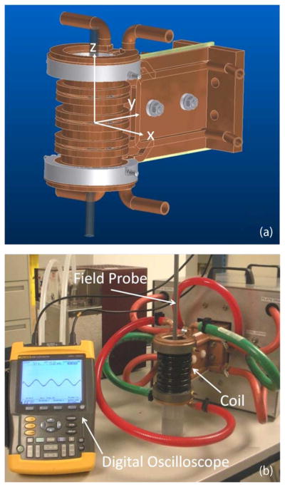
(a) 3-D CAD drawing of inductor design. The grey rings represent the magnetic flux concentrator material. The x-y-z coordinate axis originating at the coil center is shown. (b) Fabricated inductor mounted to capacitance matchbox with centrally placed field probe. Field probe output voltage and frequency are measured with a digital oscilloscope/multimeter.
Following fabrication the custom induction coil is mounted to a 4 mega volt-amperes reactive (MVAr) external heat station (AMF Life Systems, Inc., Auburn Hills, MI) connected to an 80 kW, 135–440 kHz industrial induction power (AMF Life Systems, Inc., Auburn Hills, MI) by a flexible cable (AMF Life Systems, Inc.). The system can be tuned to a particular frequency in its range or to account for the impedances of varying output coils by adjusting the capacitance of the matchbox or the power supply as well as by adjusting the series inductor inside the power supply. Field amplitude can be dynamically controlled by adjusting the power supply output voltage. Heat station components and their operation have been previously described [23]. The mounted coil, along with the magnetic field probe described below, is depicted in Fig. 2(b). Together the power supply, matchbox, and coil form a resonant circuit. These three components are cooled with a closed-loop, circulating water system maintained between 22°C and 28°C (Dry Cooler Systems, Inc., Auburn Hills, MI). The water system provides cooling from a 200-L reservoir with a flow rate of 100 L/min at 900 kPa.
C. Magnetic Field Probe
The field output of the manufactured coil was measured with a commercial 2-D magnetic field probe (AMF Lifesystems, Inc.) (Fig. 3) by measuring the amplitude in the center of the coil for several voltage settings and fitting a linear expression (weighted-least-squares) to the data. To our knowledge, this is the only available probe for measurements of AC magnetic fields at frequencies >100 Hz. The probe comprises two sensors perpendicular to one another that measure induced voltage in the axial, Fig. 3(a), and radial, Fig. 3(b), directions when exposed to alternating magnetic fields. The probe is rated to 80 kA/m for continuous and sustained exposure at 150 kHz and can be used in excess of 120 kA/m for short duration measurements at this frequency range. The field probe was used to map the axial component of the field amplitude along both the axial and transverse directions of the coil, with the former providing data to inform the alignment of magnetic nanoparticle samples. Following the manufacturer’s directions, the magnetic field is calculated from the voltage readings of the probe with the following equations:
Fig. 3.

Images of the field probe tip showing direction of field measured by the (a) axial field sensor and (b) radial field sensor. The radial field sensor only detects the component of the flux perpendicular to the sensor. The probe diameter is 9.5 mm and the body is ~75 cm.
- Magnetic flux density in axial direction:
(1) - Magnetic flux density in radial direction:
(2) - Magnitude of magnetic flux density:
(3)
U is the voltage reading from the oscilloscope (Volts), and S is the sensitivity factor (provided by manufacturer). There is one coefficient for radial (r) and one for axial (a)), f is frequency in kHz, and B has units of Tesla.
D. Measurement of Axial and Transverse Field Amplitude
Measurements taken with the magnetic field probe were used to compare the field output inside the solenoid with the calculated results. To measure the axial field the probe was positioned along the z-axis of the coil using a 48 mm diameter polycarbonate fixture inside the coil. The probe was inserted into a central hole drilled to a depth of ~60 mm along the axis of the fixture. The field was measured along the ~16 cm length of the coil axis by shifting the cylindrical fixture along the axis in 1-cm increments.
Field amplitude was also measured in the transverse direction, along the x-axis (from left to right) at the coil center and along the y-axis (from front to back). The field probe was positioned using an additional polycarbonate fixture. Six holes of 9.5 mm diameter, matching the probe diameter, were drilled to a depth of ~57 mm along the fixture diameter with a pitch of 7 mm, providing measurement sites spanning ~35 mm of the ~48 mm inner diameter of the coil. The field was measured across the diameter by sequential placement of the probe in the fixture holes. The fixture was rotated 90° between the x-axis and y-axis measurements.
III. Results
A. Comparison of Simulation Data
Fig. 4 shows field amplitude color maps of the x-z plane from Flux2D simulation of the modified solenoid. The calculated distribution of magnetic field in the simulated coil with concentrating rings is shown in Fig. 4(a). It is clear that the uniformity of the magnetic field in the box exceeds the requirements set for the specifications of 100 kA/m +/− 10 kA/m. The parameters of the induction coil to produce this field were 707 V root-mean-square (rms) and 2210 A at 150 kHz. This allows for a voltage drop in the leads, capacitor battery and supplying cable of 93 V. This level is reasonable based upon experience with these components and the unit.
Simulated field results without the flux concentrator rings are shown in Fig. 4(b) for comparison. The magnetic field distribution for the coil without flux concentrator rings also exceeds the minimum criteria specified for field uniformity. The parameters of the induction coil to produce this field were 693 V rms and 2380 A at 150 kHz for the coil without flux concentrators, which is 5.5% higher than for the coil with flux concentrator rings. Both coils (with and without flux concentrator rings) clearly meet the minimum criteria and provide very similar magnetic field distributions in the minimum required volume. The benefit of flux concentrator rings is the total continuous volume that meets the criteria specified for acceptable field uniformity of 100 kA/m +/− 10 kA/m. The advantages offered by the flux concentrating rings are apparent near the windings and that the uniform field strength extends closer to the ends of the coil.
Fig. 4(c) and (d) show the variation in field strength at radii of 0, 10, 20, and 22.5 mm versus distance from the center of the induction coil for the coil with ring concentrators and without, respectively. Inspection of the figures shows that the coil meets the uniformity criteria for a radius of 22.5 mm and a length of 74 mm (37 mm × 2) with flux concentrating rings, whereas this uniform radius is 20 mm and distance is 68 mm (34 mm × 2) with no concentrating rings. Therefore, the volume that meets the minimum specified field uniformity criteria for the coil without a magnetic core was 27% smaller, despite requiring 5.5% higher kVAr.
B. Comparison of Measured Field With Simulation
1) Axial Field Data
For comparison with simulation, we used the magnetic field probe to measure field amplitude from the solenoid along the z-axis at target field values of 95 kA/m, corresponding to power supply output voltages of 750 V. Measurements were taken in 1-cm increments over the 16-cm range of the coil axis; the mean of five measurements was calculated for each position and each power setting. The range of data points is shown in Fig. 5, along with results obtained from the Flux2D FEA simulation calculated with 650 V input at 150 kHz. As before, the FEA peak field value was 99.2 kA/m with uniformity ≥90% of peak over a length of 73.1 mm along the center-line. Measured amplitude with a coil voltage of 650 ± 10 V (750 V at power supply) and a power supply current reading of 609 A produced a field having 95.8 ± 0.4 kA/m (P2P) at 149 kHz and a uniformity range ≥90% of peak of 66 ± 3 mm. The measured value of field amplitude is comparable (3% lower) than that predicted from simulation, while the area of uniformity is 10% smaller.
Fig. 5.

Axial field amplitude curve from simulation with 650 V applied to the coil (black line) and from measurement with the magnetic field probe with power supply output voltage setting of 750 V. The power supply output voltage of 750 V corresponded to a voltage of 650 ± 10 V at the coil. X- and Y-error bars representing ±1 S.D. of mean of five measurements are displayed, but not visible on the scale of this plot.
For the axial data relatively small variances are observed in each measurement, generally less than 5%, and some variance is observed in the asymmetry of the curves. While the former is related to power supply stability and measurement error the latter may be attributed to the increased length of the probe present in the coil for measurements toward the bottom of the coil.
2) Transverse Field Data
Field amplitude along the x- and y-axes were measured, i.e. along the diameter of the coil passing through the center, for target value of peak field amplitude of 95 kA/m, corresponding to power supply output voltages of 745 V. For the 745 V power setting (609 A power supply current) the frequency was 149 kHz and the measured coil voltage was 650 ± 10 V. For each measurement position the mean of five voltage measurements was calculated.
The range of data is plotted in Fig. 6(a) for the coil x-axis and in Fig. 6(b) for the coil y-axis, with the Flux 2D FEA simulation data shown for the coil x-axis Fig. 6(a). The data over the measured range, covering 35 mm, show maximum variations of 5% or less from the mean, easily conforming to the original device specification of ±10% P2P amplitude over a diameter ≥30 mm. Variance is in part attributable to the geometrical variations at the back of the coil where the inter-turn connections differ from the cylindrical shape of each turn. Here production of field gradients diverging from the overall profile of the inner coil volume [Fig. 4(a)] may be expected. Additionally the finite dimensions of the field probe sensor along with its rotational and longitudinal position during measurement may introduce some variation between measurements sites, especially near the back of the coil. Variance also appears to be magnified at higher power (data not shown), although not exceeding 5%, and perhaps only scales with the overall field output.
Fig. 6.

Field probe data along the x-axis (left-to-right side) (a) and y-axis (front-to-back) (b) of the solenoid with concentrator rings taken at 650 V (at coil). The data set on each graph were obtained at target value of peak field amplitude of 95 kA/m. The 95 kA/m value was measured at a frequency of 149 kHz.
The results of both simulations (with and without flux concentrating rings) are summarized in Table I. Also shown in Table I are the measured results for direct comparison with the calculated values. It is apparent that, according to measurements, the predicted benefit of adding concentrating rings was not fully realized, yet there is measurable improvement over predicted values without the rings. Some of the deviation may result from measurement uncertainties. Methods to reduce the observed variance, in both the axial and transverse directions, may include more effective coil cooling during high power operation or further stabilizing the power supply output. However these variances are not unusual at high power and at this frequency, nor do they exceed the design specifications for generating uniform fields for the desired applications.
TABLE I.
Summary of Peak Field Amplitude and Uniformity Data
| Solenoid Type | Simulation (S), Measurement (M) | Peak Field Amplitude at Center1 (kA/m) | Range of Uniformity (≥ 90% of peak ampl.)1 (mm) |
|---|---|---|---|
| Modified, no flux concentrator | S | 94.2 | 68.6 ± 0.4 |
| Modified, with flux concentrator | S | 99.2 | 73.1 ± 0.4 |
| M | 95.8 ± 0.4 | 66 ± 3 |
As simulated or measured with 650 ± 10 V applied to the coil at 150 ± 1 kHz.
IV. Conclusion
We have described a solenoid that operates with reduced power and voltage losses and is thus capable to generate uniform magnetic flux density within a significant volume in the coil at high power. This design is a significant improvement over simple solenoids that often have significant field inhomogeneity and losses. These improvements were realized with structural design modifications and the addition of magnetic flux concentrator rings on the coil ends. The addition of the magnetic field concentrator rings provides an additional increase of 5% of field amplitude and 27% of uniformity over the structural modifications alone. A comparison of the measured field and uniformity values at peak output from the coil with simulation results show that the structural modifications contribute to the field amplitude and uniformity, while the contribution of the flux concentrator rings enhances uniformity. Together the results enable more accurate characterization of the AMF heating of magnetic nanoparticles as the entire sample is enveloped in a uniform magnetic field. The modified solenoid will also be useful for small animal experiments with distributed magnetic nanoparticles in vivo, as the bulk of the mouse can be enveloped in a uniform magnetic field. We hope that these results will motivate a renewed interest in design and engineering techniques for solenoids for applications requiring enhanced field uniformity, utility, and efficient power delivery.
Acknowledgments
This work was supported by the Prostate Cancer Foundation/Safeway STAR.
Footnotes
Color versions of one or more of the figures in this paper are available online at http://ieeexplore.ieee.org.
References
- 1.Ehrmann K, Saillen N, Vincent F, Stettler M, Jordan M, Wurm FM, Besse PA, Popovica R. Microfabricated solenoids and Helmholtz coils for NMR spectroscopy of mammalian cells. Lab on a Chip. 2007;7:373–380. doi: 10.1039/b614044k. [DOI] [PubMed] [Google Scholar]
- 2.Minard KR, Wind RA. Solenoidal microcoil design—Part I: Optimizing RF homogeneity and coil dimensions. Concepts Magn Reson. 2000;13:128–142. [Google Scholar]
- 3.McCann C, Sherar MD. Development of a novel loosely wound helical coil for interstitial radiofrequency thermal therapy. Phys Med Biol. 2006;51:3835–3850. doi: 10.1088/0031-9155/51/15/016. [DOI] [PubMed] [Google Scholar]
- 4.Ellinger DC, Chute FS, Vermeulen FE. Evaluation of a semi-cylindrical solenoid as an applicator for radio-frequency hyperthermia. IEEE Trans Biomed Eng. 1989;36:987–994. doi: 10.1109/10.40799. [DOI] [PubMed] [Google Scholar]
- 5.Tasci TO, Vargel I, Arat A, Guzel E, Korkusuz P, Atalar E. Focused RF hyperthermia using magnetic fluids. Med Phys. 2009;36:1906–1912. doi: 10.1118/1.3106343. [DOI] [PMC free article] [PubMed] [Google Scholar]
- 6.Jordan A, Wust P, Scholz R, Faehling H, Krause J, Felix R. Magnetic fluid hyperthermia (MFH) In: Hafeli U, Zborowski M, Schutt W, editors. Scientific and Clinical Applications of Magnetic Carriers. New York: Plenum Press; 1997. pp. 569–595. [Google Scholar]
- 7.Stauffer PR, Sneed PK, Hashemi H, Phillips TL. Practical induction heating coil designs for clinical hyperthermia with ferromagnetic implants. IEEE Trans Biomed Eng. 1994;41:17–28. doi: 10.1109/10.277267. [DOI] [PubMed] [Google Scholar]
- 8.Tominaka T. Magnetic field calculation of an infinitely long solenoid. Eur J Phys. 2006;27:1399–1408. [Google Scholar]
- 9.Popov GM. Uniformity and nonuniformity coefficients of the magnetic field produced by a solenoid of arbitrary length. Meas Techniques. 1998;41:569–571. [Google Scholar]
- 10.Kashevsky BE, Kashevsky SB, Prokhorov IV. Dynamic magnetic hysteresisin a liquid suspension of acicular maghemite particles. Particuology. 2009;7:451–458. [Google Scholar]
- 11.Kashevsky BE, Prokhorov IV, Kashevsky SB. Audio-frequency heating of particulate magnetic systems. China Particuology. 2007;5:84–92. [Google Scholar]
- 12.Bordelon DE, Cornejo C, Grüttner C, DeWeese TL, Ivkov R. High-Amplitude Range Characterization of Magnetic Nanoparticle Heating Reveals Magneto-Structural Differences. Baltimore, MD: Johns Hopkins University School of Medicine; 2010. [Google Scholar]
- 13.Glöckl G, Hergt R, Zeisberger M, Dutz S, Nagel S, Weitschies W. The effect of field parameters, nanoparticle properties and immobilization on the specific heating power in magnetic particle hyperthermia. J Phys: Condens Matter. 2006;18:2935–2949. [Google Scholar]
- 14.Natividad E, Castro M, Mediano A. Accurate measurement of the specific absorption rate using a suitable adiabatic magnetothermal setup. Appl Phys Lett. 2008;92:093116. [Google Scholar]
- 15.Natividad E, Castro M, Mediano A. Adiabatic vs. non-adiabatic determination of specific absorbtion rate of ferrofluids. J Magn Magn Mater. 2009;321:1497–1500. [Google Scholar]
- 16.Kallumadil M, Tada M, Nakagawa T, Abe M, Southern P, Pankhurst QA. Suitability of commerical colloids for magnetic hyperthermia. J Magn Magn Mater. 2009;321:1509–1513. [Google Scholar]
- 17.Atsumi T, Jeyadevan B, Sato Y, Tohji K. Heating efficiency of magnetite particles exposed to AC magnetic field. J Magn Magn Mater. 2007;310:2841–2843. [Google Scholar]
- 18.Eggeman A, Majetich S, Farrell D, Pankhurst Q. Size and concentration effects on high frequency hysteresis of iron oxide nanoparticles. IEEE Trans Magn. 2007;43:2451–2453. [Google Scholar]
- 19.DeNardo SJ, DeNardo GL, Natarajan A, Miers LA, Foreman AR, Gruettner C, Adamson GN, Ivkov R. Thermal dosimetry predictive of efficacy of 111 In-ChL6 nanoparticle AMF-induced thermoablative therapy for human breast cancer in mice. J Nucl Med. 2007;48:437–444. [PubMed] [Google Scholar]
- 20.Grüttner C, Müller K, Teller J, Westphal F, Foreman A, Ivkov R. Synthesis and antibody conjugation of magnetic nanoparticles with improved specific power absorption rates for alternating magnetic field cancertherapy. J Magn Magn Mater. 2007;311:181–186. [Google Scholar]
- 21.Grüttner C, Teller J, Schütt W, Westphal F, Schümichen C, Paulke BR. Preparation and Characterization of Magnetic Nanospheres for in vivo Application. In: Hafeli UO, Schütt W, Teller J, Zborowski M, editors. Scientific and Clinical Application of Magnetic Carriers. New York: Plenum Press; 1997. pp. 53–68. [Google Scholar]
- 22.Ruderhausen S, Grüttner C, Frank M, Teller J, Westphal F. Multifunctional superparamagnetic nanoparticles for life science applications. Eur Cells Mater. 2002;3:81–83. [Google Scholar]
- 23.Kumar A, Mallipudi R, Cornejo C, Bordelon D, Armour M, DeWeese TL, Ivkov R. Water Shielding of Solenoid Coils Reduces Non-Specific Tissue Heating. Baltimore, MD: Johns Hopkins Medical Institute; 2010. [Google Scholar]
- 24.Jain SK, Naik PA, Hannurkar PR. Design, fabrication, and characterization of a solenoid system to generate magnetic field for an ECR proton source. Sadhana. 2010;35:461–468. [Google Scholar]