Abstract
We present a comprehensive study of a class of multi-band miniaturized patch antennas designed for use in a 3D enclosed sensor array for microwave breast imaging. Miniaturization and multi-band operation are achieved by loading the antenna with non-radiating slots at strategic locations along the patch. This results in symmetric radiation patterns and similar radiation characteristics at all frequencies of operation. Prototypes were fabricated and tested in a biocompatible immersion medium. Excellent agreement was obtained between simulations and measurements. The trade-off between miniaturization and radiation efficiency within this class of patch antennas is explored via a numerical analysis of the effects of the location and number of slots, as well as the thickness and permittivity of the dielectric substrate, on the resonant frequencies and gain. Additionally, we compare 3D quantitative microwave breast imaging performance achieved with two different enclosed arrays of slot-loaded miniaturized patch antennas. Simulated array measurements were obtained for a 3D anatomically realistic numerical breast phantom. The reconstructed breast images generated from miniaturized patch array data suggest that, for the realistic noise power levels assumed in this study, the variations in gain observed across this class of multi-band patch antennas do not significantly impact the overall image quality. We conclude that these miniaturized antennas are promising candidates as compact array elements for shielded, multi-frequency microwave breast imaging systems.
Index Terms: microstrip antennas, miniaturized antennas, multi-band antennas, slot-loading, microwave breast imaging
I. Introduction
The imaging of breast tissue dielectric properties at microwave frequencies has been identified as a promising technology for improving breast cancer screening and diagnosis [1]. An array of antennas transmits low-power microwave signals into the breast. The measured scattered signals are used to reconstruct the spatial distribution of the dielectric properties throughout the breast volume via a solution of the inverse scattering problem. Recent research (e.g., [2]–[11]) points to the utility of microwave tomographic imaging as a low-cost, non-ionizing, and quantitative 3D imaging modality. It is a promising technology not only for early detection of breast cancer, but also for monitoring changes in breast tissue in response to prevention and treatment protocols (e.g., [11]) and for evaluating breast density for individualized risk assessment (e.g., [10]).
In this paper, we investigate performance characteristics of a class of slot-loaded patch antennas that satisfy what we believe are the most important design criteria for a 3D array-based microwave breast imaging system. A system design that permits microwave breast imaging to be rigorously validated against a 3D clinical benchmark such as magnetic resonance imaging (MRI) is of critical importance. MR and microwave image co-registration is easily and reliably achieved using a patient interface that maintains the same position of the breast during both the MRI and microwave scans. Our overarching design strategy is to configure the 3D microwave antenna array to occupy the space vacated by removable breast coils in the patient support platform of a breast MRI system. This approach enables the microwave scan to take place with the patient on the MRI table, outside of the MRI bore. A thermoplastic mesh is used to maintain the position of the breast for both MRI and microwave scans and a biocompatible immersion medium that is impedance matched to the mesh is used to fill the space between the array elements and the breast [12]. This design strategy imposes a constraint on the overall size and layout of the antenna array system and necessitates the use of miniaturized antennas.
Additional antenna design criteria are influenced by factors that affect the ill-posedness of the inverse scattering problem [13], the computational efficiency of microwave imaging algorithms, and the quality of microwave images. These factors include the spatial sampling density (e.g. the number and location of receivers for measuring the scattered fields), frequency sampling density (e.g. the number of frequencies used for data acquisition), frequency range and corresponding penetration depth in breast tissue, susceptibility of the antennas to noise and interference, and complexity of the antenna model in the forward solver of an iterative inverse scattering algorithm.
Collectively, these considerations lead to the following prescribed set of characteristics for the 3D antenna array in a microwave tomography system that is suitable for MRI-based validation:
compact
shielded from the outside environment
densely populated with miniaturized antenna elements
relatively simple to model
composed of elements that operate efficiently at multiple frequencies within the frequency range of interest (~0.5–3.5 GHz)
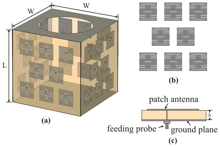
These characteristics are exhibited by the 3D antenna array shown in Fig. 1, wherein the breast of the prone patient extends downward through the opening in the top panel [14]. The array, as shown, is populated with 32 miniaturized, slot-loaded patch antennas and has a total linear dimension (L+W+W) of less than 50 cm. The ground-plane backing on the array ensures unidirectional radiation and minimizes environmental interference. The planar layout of the array, patches, and slots is easy to model in Cartesian-grid-based forward simulations of the inverse scattering algorithm. The specific elements shown in Fig. 1 represent one of several types of slot-loaded multi-band patch antennas examined in this paper.
Fig. 1.
3D microwave sensor array configuration. (a) 3D view showing side walls populated with patch antennas and top and bottom panels composed of metal planes. The top metal plane includes an opening that allows the breast to be suspended in the imaging volume. (b) Frontal view of one panel of the proposed array showing eight slot-loaded, miniaturized patch antennas. (c) Cross-sectional view of one slot-loaded, miniaturized patch antenna.
The existence of numerous prior studies of antennas designed for microwave breast imaging begs the question: Why investigate slot-loaded microstrip patch antennas for this application rather than use a previously proposed design? The most widely used antennas for microwave tomography are monopoles and dipoles (e.g., [2]–[5], [9]–[11], [15]–[16]). These antennas are easy to fabricate and simple to model in the forward solution of the inverse problem, but they are difficult to arrange densely in a 3D array, particularly one that is designed for the constrained space of an MRI patient support platform. Additionally, they are omni-directional radiators and thus sensitive to environmental interference unless operating in a lossy immersion medium (which also reduces sensitivity to the desired signals). A few patch antenna designs have been previously proposed for use in enclosed arrays [17], [18]; however, those antennas operate at a single frequency. Ultrawideband (UWB) antennas have also been explored in a large number of studies, primarily in the context of radar-based imaging techniques (e.g., [19]–[24]). However, the use of frequencies in the UWB range (~3–10 GHz), rather than frequencies in the UHF band (up to ~3 GHz), exacerbates the ill-posedness of the inverse problem and creates challenges with imaging the uncompressed breast due to limited penetration depths at those higher frequencies.
Slot-loading techniques can be used to reduce the size of a patch antenna and produce multi-band operation within a specified frequency range [25]–[34]. The ratio between frequencies of operation can be tuned by varying the dimensions of the slot(s) [25]–[28], [30]–[31]. Several examples of single-layer slot-loaded patch antennas have been reported, including a dual-band miniaturized antenna for microwave breast imaging [35]. However, while the gain of some slot-loaded patches has been evaluated [28]–[34], there has been no comprehensive investigation of the trade-off between miniaturization and gain to date.
In this paper, we present the design and realization of a class of multi-band (dual-, tri-, and quad-band) miniaturized antennas, based on the well-known slot-loading concept, that are suitable for compact, shielded microwave breast imaging arrays. Our investigation focuses on the following:
an experimental characterization of representative dual-, tri-, and quad-band miniaturized patch antenna designs and comparison with simulation results
a comprehensive numerical analysis of the effects of the location and number of slots, as well as the thickness and permittivity of the dielectric substrate, on not only resonant frequency, but also gain
a comparison of reconstructions of the dielectric properties of an anatomically realistic numerical breast phantom from simulated measurements using 3D enclosed antenna arrays that incorporate two types of slot-loaded miniaturized patch antenna considered here.
The latter permits the determination of the extent to which the variations in gain observed across this class of antennas impact the overall image quality achieved using an enclosed array of the antennas.
The remainder of the paper is organized as follows. In Section II (Antenna Design), we present the underlying design principles for the class of antennas investigated in this paper. Section III (Results) provides simulated and measured resonant frequencies, gain, and radiation patterns for three representative multi-band antennas from the class of slot-loaded patches, namely a dual-, tri-, and quad-band antenna. Section III also provides a simulation-based investigation of the effects of the type of slot and the substrate properties on the resonant frequency and gain. Section III culminates with a simulation-based investigation of the impact of gain on the performance of a multi-band miniaturized patch antenna array in imaging breast phantoms in the presence of noise. In Section IV we provide concluding remarks.
II. Antenna Design
Our antenna miniaturization strategy is to load a rectangular patch with judiciously placed slots to shift additional higher-order resonant modes into the desired frequency range while maintaining current distributions similar to that of the dominant mode. We illustrate this process in what follows by summarizing the effect of slot loading, reviewing the design guidelines of a miniaturized patch antenna previously presented [35], and presenting several proposed designs for multi-band operation. We also establish the terminology we use for the different types of slots examined in our study. In the discussion that follows, we define the multi-band response of the antenna to be in terms of the number of modes with broadside radiation patterns and resonant frequencies within the 0.5–3.5 GHz range. In a rectangular patch, the radiation patterns of the second (TM200) and fourth (TM400) longitudinal modes have nulls on the broadside direction due to anti-symmetric current distributions. Thus the longitudinal modes of interest in this work are the first (TM100), third (TM300), and fifth (TM500).
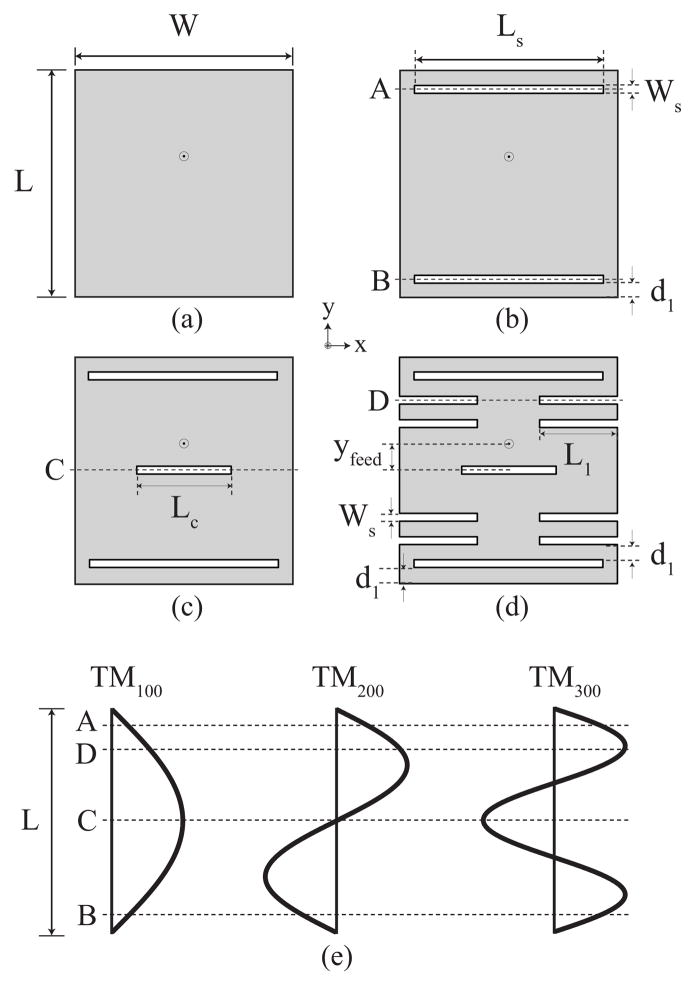
Fig. 2 illustrates the topology of a rectangular patch antenna (Fig. 2(a)), loaded with a series of slots (Fig. 2(b)–(d)). A patch antenna comprising two radiating-edge slots (RS) parallel to and near the radiating edges, shown in Fig. 2(b), was reported in [28]. In this structure, the lower frequency of operation is determined by the resonant frequency, f100, of the dominant mode, TM100, while the higher operating frequency is determined by the resonant frequency, f300, of a perturbed higher-order longitudinal mode, TM300. The addition of the RS has a slight effect on reducing f100 from that of a basic patch, since the slots at A and B are located close to the current minima of the dominant TM100, as shown in Fig. 2(e). The RS have a more significant effect in reducing f300, since the current for the TM300 mode, illustrated in Fig. 2(e), is more significant in the regions of these slots.
Fig. 2.
Top view of the (a) basic patch, (b) patch loaded with radiating-edge slots (RS), (c) patch loaded with radiating-edge and center slots (RS+CS), and (d) patch loaded with radiating-edge, center, and non-radiating edge slots (RS+CS+NRS). (e) Schematic of current distributions for the first three longitudinal modes showing where the current is affected by the various slots in (b)–(d).
Fig. 2(c) illustrates a patch antenna with an additional slot located at the center of the patch. The center slot (CS) increases the electrical lengths of the current paths for the first and third modes, since it is located in a region, C, where both these modes have current maxima, as shown in Fig. 2(e). Thus, increasing the length of the CS reduces the operating frequencies of these two bands. The effect is more significant for f300, since the slot is electrically longer for the TM300 mode.
Fig. 2(d) shows the addition of non-radiating-edge slots (NRS) that cause the current paths of all longitudinal modes to be further increased, thereby permitting a greater reduction in the length of the patch [35]. The NRS located at D, as shown in Fig. 2(e), has a slight effect on the current distribution of the TM100 mode and a more significant effect on the current distribution of the third mode, TM300. The resonant frequencies of the TM100 and TM300 modes of the RS+CS+NRS patch antenna were reduced by 37% and 23% [35], respectively, compared to an RS patch antenna [28]. In general by reducing the width of the slots a slightly higher level of miniaturization can be achieved [36].
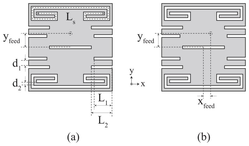
Fig. 3 shows the topology of additional slot-loaded patch antenna designs for tri- and quad-band operation. The loading effect of the RS is limited by the width of the patch [28]. To overcome this limitation, radiating-edge spiraled (RSS) replace the straight slots near the radiating edges slots. The addition of the RSS has an effect on the TM100, TM300 and TM500 modes.
Fig. 3.
Top view of the patch loaded with radiating-edge spiraled, center, and non-radiating edge slots (RSS+CS+NRS). (a) Standard feed location for tri-band operation. (b) Offset feed for quad-band operation.
The resulting tri-band (RSS+CS+NRS) miniaturized patch antenna, shown in Fig. 3(a), comprises two RSS (length Ls and width Ws) near the radiating edges of the patch, one CS (length Lc and width Ws), and several NRS (lengths L1 and L2 and width Ws). An added benefit of using the spiral slot is that, in conjunction with the center slot, it offers a greater flexibility not only in reducing the operating frequencies of the TM300 and TM500 modes, but also in determining the separation between the operating frequencies of the TM100 and TM300 modes. There are two primary reasons for this flexibility. First, the location of the spiral slots at the edge of the patch results in considerable loading of the TM300 mode and negligible loading of the TM100 mode. Second, the shift in the resonant frequency of the TM300 mode is determined by the reactance of the loading RS slot, which in turn is determined by its overall electrical length. Therefore, by spiraling the RS to achieve an RSS, the slots electrical length can be increased as desired to obtain loading reactance values that reduce the resonant frequency of the TM300 mode as desired. Using the structure presented in [35], the ratio between the two frequencies of operation (f300/f100) can only be changed in a limited range of 1.6–2.0, where f300 and f100 refer to the operating frequency of the TM300 and TM100 modes, respectively. However, using the tri-band topology, this ratio can be designed to be as small as 1.0 and as large as 3.0. This means that the resonant frequencies of both modes can be merged together to achieve a wider band of operation than that of either mode, if desired, and a considerably larger fractional bandwidth can be achieved than what is achievable using a single resonant mode patch.
The topology of the quad-band miniaturized patch antenna is the same as that of the tri-band (RSS+CS+NRS) patch, except the feed is located off the axis of symmetry of the structure, as shown in Fig. 3(b). The off-axis feed yields a quad-band response by exciting the dominant orthogonal mode, TM010. The polarization of this mode is perpendicular to the polarization of the aforementioned longitudinal modes. This, however, is not expected to be a problem for the intended microwave imaging application for the following reason. The transmit and receive antennas in the microwave imaging array are polarization-matched; since breast tissue presents such a heterogeneous scattering environment, the quality of information in the scattered signals is similar regardless of polarization of the transmit-receive pair at a given frequency of operation.
The multi-band miniaturized patch antennas were designed to operate in a biocompatible immersion medium comprised of safflower oil. This medium fills the void between the microwave sensor array and the breast. We characterized the dielectric properties of the immersion medium using an Agilent 85070D dielectric probe kit and E8364 vector network analyzer (VNA). The following second-order dispersion model in CST Microwave Studio [37] was fit to the measured frequency-dependent complex permittivity of the safflower oil:
| (1) |
Since the accuracy of the probe increases at higher frequencies for materials with low relative permittivity values (e.g., εr in the range of 2–5) [38], we incorporated higher frequency data content into the curve-fitting procedure. The fit was performed over the frequency range of 0.5–5 GHz. The resulting second-order dispersion model parameters are as follows: ε∞ = 2.15, α0 = 195.47 × 10¹⁸ s−2, α1 = 88.20 × 10⁹ s−1, β0 = 292.62 × 10¹⁸ s−2, β1 = 63.83 × 10⁹ s−1.
The dimensions of dual-, tri-, and quad-band miniaturized patch antennas patterned on a 10 cm × 10 cm Rogers RO4003 substrate (32 mil, εr = 3.55) and immersed in oil were tuned in CST Microwave Studio to achieve operating frequencies within the 0.5–3.5 GHz frequency range. The resulting physical dimensions for the dual-band (RS+CS+NRS) antenna shown in Fig. 2(d) are as follows (in mm): W=28, L=29, Ws=1, Ls=24, Lc=12, L1=10, d1=2, and yfeed=4.5. The resulting physical dimensions for the tri-band (RSS+CS+NRS) and quad-band (RSS+CS+NRS, offset feed) antennas shown in Fig. 3 are as follows (in mm): W=32, L=33, Ws=1, Ls=82, Lc=16, L1=7, L2=8, d1=2, and d2=1. The coordinates of the feed location, relative to the center of the patch, are as follows (in mm): (xfeed=0, yfeed=8.5) for the tri-band and (xfeed=3, yfeed=8.5) for the quad-band patch.
III. Results
A. Simulations and Measurements of Dual-, Tri-, and Quad-Band Antennas
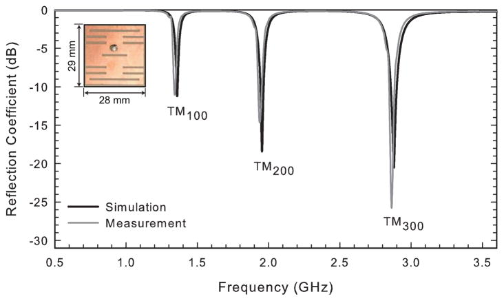
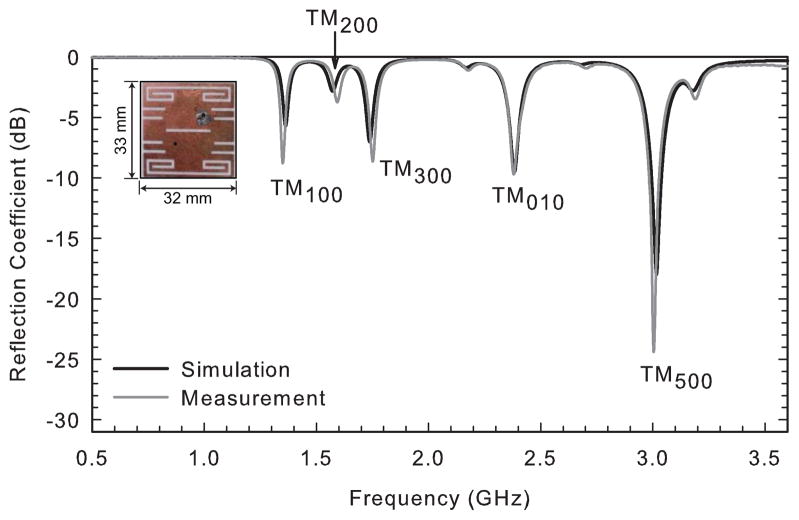
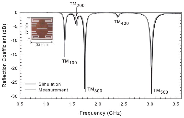
The calculated input reflection coefficients for the dual-band (RS+CS+NRS), tri-band (RSS+CS+NRS), and quad-band (RSS+CS+NRS, offset feed) antennas are shown in Figs. 4–6. The dual-band antenna exhibits TM100 and TM300 resonances at 1.36 GHz and 2.88 GHz, respectively, whereas the tri-band antenna exhibits TM100, TM300, and TM500 resonances at 1.36 GHz, 1.74 GHz, and 3.03 GHz, respectively. The miniaturization technique used in the tri-band antenna reduces the operating frequencies of its TM100, TM300, and TM500 modes by 48%, 78%, and 77%, respectively, compared to a basic patch antenna occupying the same area. The ratio between the frequencies of operation is f300/f100 = 1.3 and f500/f100 = 2.2. A comparison of Figs. 4 and 5 shows that the combination of the spiral loading on the radiating-edge slots and the wider center slot not only brings f500 down into the range of interest, but also further reduces f300 by 40% relative to the dual-band (RS+CS+NRS) antenna. The additional resonance of interest of the quad-band antenna, the TM010, occurs at 2.38 GHz.
Fig. 4.
Simulated and measured reflection coefficients of the dual-band miniaturized patch antenna of Fig. 2(d) immersed in safflower oil.
Fig. 6.
Simulated and measured reflection coefficients of the quad-band miniaturized patch antenna of Fig. 3(b) immersed in safflower oil.
Fig. 5.
Simulated and measured reflection coefficients of the tri-band miniaturized patch antenna of Fig. 3(a) immersed in safflower oil.
We experimentally validated the dual-band (RS+CS+NRS), tri-band (RSS+CS+NRS), and quad-band (RSS+CS+NRS, offset feed) miniaturized patch antenna designs. The antenna elements were probe fed using the center conductor of an SMA connector and immersed in a 32 cm × 15 cm × 11 cm tank filled with safflower oil for all measurements described below.
The measured input reflection coefficients, S11, of these multi-band miniaturized antennas are compared with the simulation results in Figs. 4–6. The fabricated dual-band (RS+CS+NRS) antenna shows bands of operation at 1.34 GHz and 2.86 GHz. The fabricated tri-band (RSS+CS+NRS) antenna shows bands of operation at 1.36 GHz (TM100), 1.76 GHz (TM300), and 3.02 GHz (TM500). The operating bands of the fabricated quad-band (RSS+CS+NRS, offset feed) antenna are observed at 1.35 GHz (TM100), 1.75 GHz (TM300), 3.00 GHz (TM500), and 2.38 GHz (TM010). Excellent agreement is observed between the simulated and measured reflection coefficients for all of these multi-band antennas. This agreement provides an additional validation of the accuracy of the second-order dispersion fit of the dielectric properties of the safflower oil used in the numerical simulations of the antenna design. We note that the agreement between simulated and measured S11 curves for the dual-band (RS+CS+NRS) antenna (Fig. 4) is improved relative to that reported in [35]; that previous study used a less accurate dielectric properties model for oil.
The S11 nulls for the TM100, TM300, and TM500 modes of operation of the quad-band (RSS+CS+NRS, offset feed) antenna (Fig. 6) are not as deep as those of the tri-band (RS+CS+NRS) antenna (Fig. 5). This is attributed to the fact that the optimum feed location that results in the best impedance match is different for each mode. Thus, a compromise has to be made when using a single feed to impedance match a highly resonant structure at four different frequencies. Nonetheless, the measured S11 of this antenna is better than −8.6 dB for all frequencies of operation, which is sufficient for our intended application.
We also measured the co- and cross-polarized radiation patterns of these multi-band miniaturized patch antennas immersed in oil. These antennas are designed to be used in an enclosed array with side lengths on the order of 15 cm. Thus, the measurements were taken at a distance of 15 cm from the patch using half-wavelength dipoles.
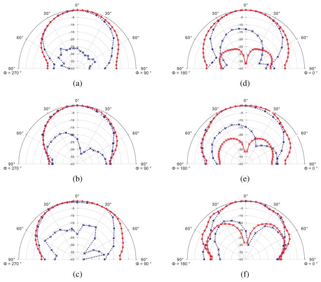
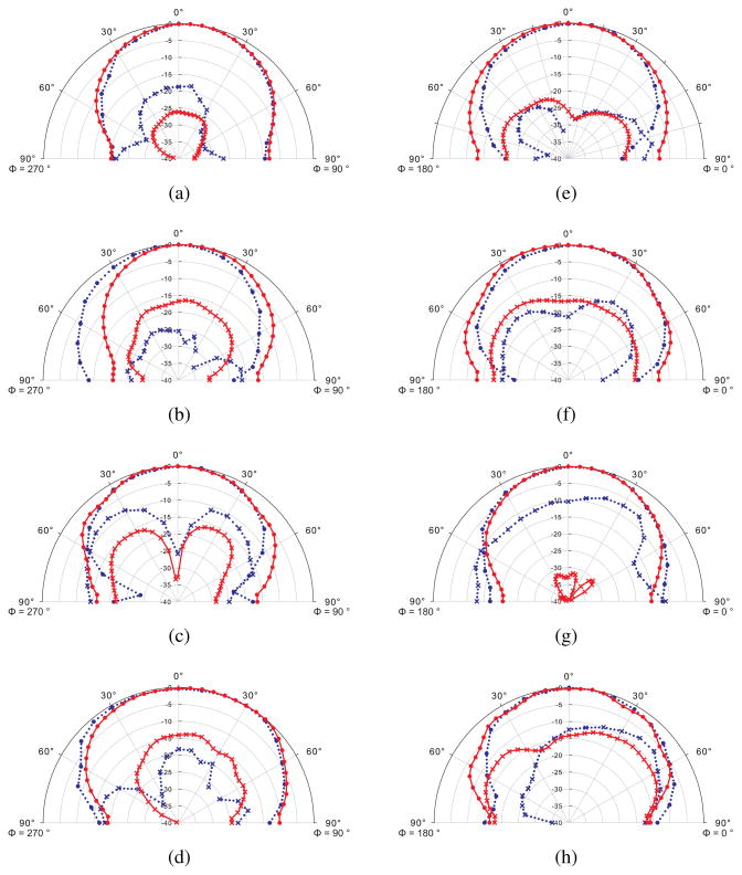
Figs. 7 and 8 show the co- and cross-polarized radiation patterns in the E- and H-planes at the frequencies of interest of the tri- and quad-band miniaturized antennas. Each antenna shows consistent radiation patterns at its different bands of operation despite having different current distributions at each frequency. This is attributed to the manipulation of the current distribution of the higher-order resonant modes of the patch by strategically locating the loading slots. Moreover, most measured cross-pol levels are at least 15 dB lower than the co-pol ones at broadside for all frequencies of interest.
Fig. 7.
Simulated and measured radiation patterns of the tri-band (RSS+CS+NRS) miniaturized patch antenna in safflower oil. The patterns are obtained at a distance of 15 cm from the patch. (a) E-plane at 1.36 GHz (b) 1.76 GHz and (c) 3.02 GHz. (d) H-plane at 1.36 GHz (e) 1.76 GHz and (f) 3.02 GHz. Solid red: simulated data. Dotted blue: measured data. Circle: co-pol. x: cross-pol.
Fig. 8.
Simulated and measured radiation patterns of the quad-band (RSS+CS+NRS, offset feed) miniaturized patch antenna in safflower oil. The patterns are obtained at a distance of 15 cm from the patch. (a) E-plane at 1.35 GHz (b) 1.75 GHz (c) 2.38 GHz, and (d)3.00 GHz. (e) H-plane at 1.35 GHz (f) 1.75 GHz (g) 2.38 GHz, and (h) 3.00 GHz. Solid red: simulated data. Dotted blue: measured data. Circle: co-pol. x: cross-pol.
Figs. 7 and 8 show good agreement between the co-pol components of the measured and the simulated radiation patterns of the two fabricated prototypes. Minor discrepancies observed between the simulation and measurement can be attributed to the effect of the feeding cables, which is not taken into account in the simulations. The greater discrepancy observed between the measured and the simulated cross-pol components is attributed to the fact that the very low cross-pol levels are more susceptible to measurement imperfections.
We also investigated the gain of the dual-band, tri-, and quad-band miniaturized patch antenna miniaturized antennas immersed in oil. The gain of the antenna is calculated from measured or simulated data using the following modified Friis transmission formula for a lossy medium [39]:
| (2) |
Here, PT, PR, GT, GR are the transmitted and received powers and the gains of the respective antennas, R is the distance between antennas, λeff = λ = 2π/Re[k], and α = |Im[k]|, where k is the wave number of the lossy medium. The effect of impedance mismatch is taken into account by including the (1 −|ΓT|2) (1 − |ΓR|2) in the above equation, where term is the reflection coefficient at the respective antenna. The gain of each antenna at the design frequency of interest was determined using two identical miniaturized patch antennas, separated by a distance of 15 cm. Because this spacing is rather small and the antennas radiate in an environment that is not lossless, the gain values reported in this work do not represent the traditional far-field gain of an antenna, whereby the antenna radiates in lossless environments and the observation point is well into the far-field.1 Nonetheless, the reported gain values can be used to compare the relative performance of different antenna types with each other (e.g. RS with RS+CS). The simulated and measured gain values at the resonant frequencies of interest for the multi-band miniaturized antennas are listed in Table I. Each row in the table is color-coded as follows: white for TM100, green for TM300, blue for TM500, and pink for TM010. We observe good agreement between the simulated and measured gain values. However, the low gain values relative to a basic patch motivates the numerical analysis presented in Section III-B.
TABLE I.
Calculated and Measured Gain of Multi-Band Miniaturized Patch Antennas
| simulated | measured | |||
|---|---|---|---|---|
| type of antenna | freq. (GHz) | gain (dBi) | freq. (GHz) | gain (dBi) |
| dual-band (RS+CS+NRS) | 1.36 | −5.2 | 1.34 | −5.5 |
| 2.88 | −6.4 | 2.86 | −5.9 | |
| tri-band (RSS+CS+NRS) | 1.36 | −6.0 | 1.36 | −5.3 |
| 1.74 | −7.0 | 1.76 | −7.6 | |
| 3.03 | −8.6 | 3.02 | −8.4 | |
| quad-band (RSS+CS+NRS, offset feed) | 1.36 | −5.9 | 1.35 | −5.3 |
| 1.74 | −7.2 | 1.75 | −7.6 | |
| 3.03 | −8.0 | 3.00 | −7.7 | |
| 2.38 | −2.4 | 2.38 | −4.3 | |
B. Effects of Slot Type
To understand the design trade-offs of slot-loading a patch antenna, we performed simulations in CST Microwave Studio of antennas loaded with slots at different locations along the patch. Table II shows eight different types of slot-loaded patch antennas considered here and the first few resonant frequencies and gain of each compared to a basic patch. The color coding convention of Table I is adopted here as well. As expected, the table illustrates that slot-loading techniques miniaturize the patch antennas at the expense of gain. However, while different types of slots produce similar reductions in frequency, some affect the gain of the antenna more adversely than others.
TABLE II.
Calculated Frequencies of Operation and Gain of Several Slot-Loaded Patch Antenna Types
| type of slot-loaded patch antenna | topology | freq. (GHz) | gain (dBi) | reduction in freq. relative to basic patch (%) | change in gain relative to basic patch (dB) |
|---|---|---|---|---|---|
| basic patch (no slots) |

|
2.58 | 6.5 | - | - |
| 7.91 | 7.7 | - | - | ||
| radiating-edge slot (RS) |

|
2.16 | 2.6 | 16 | −3.9 |
| 3.77 | 4.9 | 52 | −2.8 | ||
| center slot (CS) |

|
2.36 | 6.2 | 9 | −0.3 |
| 6.85 | 8.8 | 13 | 1.1 | ||
| non-radiating-edge slot (NRS) |

|
1.70 | −0.2 | 34 | −6.7 |
| 3.56 | −16.4 | 55 | −24.1 | ||
| radiating-edge slot spiraled (RSS) |

|
2.16 | −0.6 | 16 | −7.1 |
| 4.59 | 5.7 | 42 | −2.0 | ||
| RS + CS |

|
2.09 | 2.6 | 19 | −3.9 |
| 3.48 | 1.6 | 56 | −6.1 | ||
| RS + NRS |

|
1.42 | −4.6 | 5 | −11.1 |
| 3.02 | −3.0 | 62 | −10.7 | ||
| CS + NRS |

|
1.57 | −1.9 | 39 | −8.4 |
| 3.52 | −13.0 | 56 | −20.7 | ||
| RS + CS + NRS |

|
1.36 | −5.2 | 47 | −11.7 |
| 2.88 | −6.4 | 64 | −14.1 |
For example, loading the patch with either RS or NRS produces almost the same reduction in f300 (slightly over 50%). However, the use of NRS has a more significant effect in the reduction of gain at this frequency. RS and RS+CS designs produce a miniaturization of more than 50% at the resonant frequency of the TM300 mode with relatively good values of gain, ~2–5 dBi. The CS only slightly reduces f100 and f300 with virtually no reduction in gain relative to the basic patch. Loading antennas with a combination of slots (e.g. RS+CS, CS+NRS, and RS+CS+NRS) produces the highest degree of miniaturization at both f100 and f300. Note, however, that gain at both f100 and f300 deteriorates significantly if the design incorporates NRS.
C. Effects of Substrate Parameters
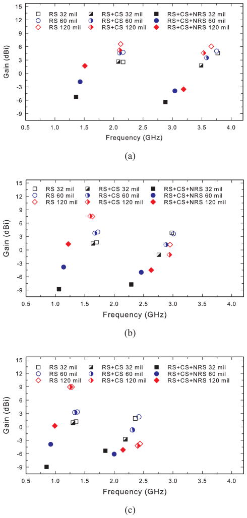
We investigated the influence of substrate parameters (dielectric constant and thickness) on the resonant frequencies and gain of several slot-loaded patch antennas. The calculated gain of dual-band (RS, RS+CS, and RS+CS+NRS) miniaturized patch antennas versus frequency is shown in Fig. 9. For this study we considered substrates with dielectric constants εr = 3.55, 6.15, and 10.2 and thicknesses h = 32 mil, 60 mil, and 120 mil. These are typical characteristics of substrate materials used in designing microstrip patch antennas.
Fig. 9.
Calculated gain versus frequency for different dielectric constants (εr) and thickness h of the substrate (32, 60, or 120 mil). (a) εr = 3.55, (b) εr = 6.15, (c) εr = 10.2.
Fig. 9 shows that the resonant frequencies of the TM100 and TM300 modes can be easily changed by changing these substrate characteristics. As expected, an increase in the dielectric constant of the antenna substrate corresponds to a decrease in the operating frequencies of the patch. In addition, an increase in the thickness of the substrate improves the calculated gain at the frequencies of operation. The maximum calculated gain is achieved for a substrate with εr = 3.55 and h = 120 mil.
D. Performance of a Multi-Band Miniaturized Patch Antenna Array in Microwave Breast Imaging
In this section, we present a computational study that not only illustrates the feasibility of 3D microwave breast imaging using multi-band, miniaturized patch antennas but also compares imaging performance between two arrays of slot-loaded patch antennas that have similar resonant frequencies but different levels of gain. Our numerical testbed consists of a Class II (scattered fibroglandular) breast phantom derived from MRI data [40] and used in a previous imaging study [10]. The phantom is enclosed by an array of 32 dual-band miniaturized patch antennas; the array topology is of the form shown in Fig. 1. The higher-gain array is populated with RS patches on a 60-mil substrate with εr=10.2 and a conductivity of 0.0024 S/m, while the lower-gain array is populated with RS+CS+NRS patches on a 60-mil substrate with εr=6.15 and a conductivity of 0.0021 S/m. We chose these specific RS and RS+CS+NRS patches for this comparison study because, as shown in Fig. 9, they offer similar frequencies of operation in the range of interest with very different levels of gain.
The four array panels containing antennas have dimensions of L=124 mm and W=164 mm. The hole in the top array panel, through which the breast phantom descends, conforms to the elliptical base of the phantom. The interior of the array is filled with an immersion material whose dielectric properties are described by a single pole Debye model with parameters ε∞ = 2.24, εs = 2.97, and τp = 5 ps. This Debye model closely matches the dielectric properties of safflower oil over the frequency range 0.5 – 3 GHz. Simulated array measurements are performed using a finite-difference time-domain (FDTD) model of this testbed with a 1-mm grid.
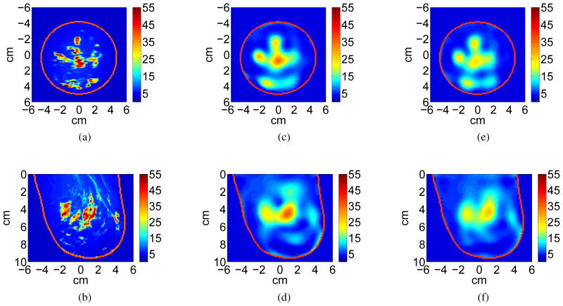
We reconstruct the dielectric profile of the breast from the simulated scattered field data using the multi-frequency inverse scattering technique described in [10]. We perform the Debye-parameter reconstruction using frequencies corresponding to the TM100 and TM300 modes of the RS patch antenna. Iterative forward solutions are performed via FDTD, also on a 1-mm grid. We add Gaussian white noise to the received signals at a power level of −70 dB referenced to the source, which is a conservative estimate for the expected noise floor of a data acquisition system. Adding noise in this manner allows us to evaluate the effect, if any, of the gain difference between antenna types while avoiding the so-called ”inverse crime”. Coronal and sagittal cross-sections through the actual 3D permittivity profile at 2 GHz (taken from the reconstructed Debye model) are shown in Fig. 10(a)–(b). The blue regions in the phantom represent adipose tissue while the orange-red regions represent fibroglandular tissue. Cross-sections through the reconstructed 3D permittivity profile at 2 GHz are shown in Fig. 10(c)–(d) for the array of RS patches. (The effective conductivity, not shown, is highly correlated with the permittivity in both the actual and reconstructed profiles.) Visual agreement between the reconstructed image and the actual phantom is evident. In particular, the regions of higher-permittivity fibroglandular tissue are faithfully reconstructed, albeit at a relatively low resolution that is characteristic of microwave imaging in the UHF band. Such imaging quality has been obtained for numerical breast phantoms representing all four classes of breast density [41].
Fig. 10.
Comparison of imaging a Class II (scattered fibroglandular) numerical breast phantom using two types of antenna arrays. Coronal (top row) and sagittal (bottom row) cross-sections of relative permittivity at 2.0 GHz. (a)–(b) Actual profile. (c)–(d) Images reconstructed from simulated data acquired using an enclosed array of RS patch antennas. (e)–(f) Images reconstructed from simulated data acquired using an enclosed array of RS+CS+NRS patch antennas.
For comparison, we also include cross-sections (Fig. 10(e)–(f)) through a reconstruction created using the array of RS+CS+NRS patches. This lower-gain patch array offers a reconstruction accuracy that is similar to that of the higher-gain patch array in terms of imaging the location and basic shape of the adipose and fibroglandular tissue regions. A quantitative measure of the quality of each reconstruction may be obtained using the fidelity metric cos(ϕ) defined in [10]. This metric is invariant to global scaling and gives cos(ϕ) = 1 for a perfect reconstruction. The reconstruction from the RS array and the reconstruction from the RS+CS+NRS array both give cos(ϕ) = 0.83, which confirms that the reconstructions are similarly faithful to the exact dielectric profile. However, the dielectric properties profile reconstructed with this RS+CS+NRS patch array is somewhat more underestimated than the higher-gain array (RS) reconstruction. We have confirmed that this difference in the absolute level of reconstructed dielectric properties is not due to the differences in average signal-to-noise ratios that result from different gain characteristics; the underestimation with the RS+CS+NRS patch array is still present in the noise-free images. Rather, the fact that the reconstructed images for the two arrays are not identical may be attributed to subtle differences in the degree of gain imbalance between the two frequency bands for each antenna. These results demonstrate the potential for using a compact, shielded array of miniaturized, multi-band patch antennas and suggest that the lower gain observed for the antennas with more slots does not outright preclude their use in imaging arrays. The variations in frequency, gain, and topological complexity across the class of miniaturized patches considered in this paper give the system designer multiple options in designing a viable enclosed array for microwave breast imaging.
IV. Summary and Conclusion
Slot-loaded, multi-band, miniaturized patch antennas for microwave breast imaging were designed, simulated, and tested. A multi-band response is obtained by exploiting the dominant longitudinal mode, TM100, and one or more higher-order modes of the patch. Miniaturization is achieved by loading the patch with a combination of slots located near the radiating edges, at the center, and/or near the nonradiating edges of the patch. Appropriate loading locations are chosen to ensure that only the desired resonant modes of the structure are affected and the structure’s symmetry is maintained. The technique makes it possible, for example, to reduce the resonant frequencies of the TM100, TM300, and TM500 modes of a tri-band patch by 48%, 78%, and 77%, respectively, compared to a basic patch antenna occupying the same area.
Prototypes of dual-, tri-, and quad-band miniaturized patch antennas were fabricated and verified experimentally in a bio-compatible immersion medium. The measured and simulated resonant frequencies of the modes of the patch antennas were observed to be in excellent agreement. Similar and symmetric radiation patterns at all bands of operation were obtained. We investigated the gain at the operating frequencies of numerous slot-loaded miniaturized patch antennas patterned on different types of substrates. The study elucidates the trade-off between miniaturization via slot-loading and gain. The study also reveals how the gain of the miniaturized patch antennas varies with the substrate dielectric constant and thickness.
We also presented a computational study that demonstrates the feasibility of using an enclosed array populated with two of the miniaturized patch antenna designs proposed here for 3D microwave breast imaging. The results suggest that these miniaturized antennas are suitable candidates as array elements for multi-band microwave breast imaging systems where unidirectional radiation, environmental shielding, and dense spatial sampling of scattered fields are desired.
Acknowledgments
This work was supported by the National Institutes of Health under R21 CA161369, the National Science Foundation under ECCS 1128049 and a Graduate Fellowship, and the Philip D. Reed Chaired Professorship.
The authors would like to thank Dr. Yazid Yusuf for insightful technical discussions and Adam Weiss for his assistance with the radiation pattern measurements.
Biographies

Suzette M. Aguilar received the B.S. degree (Hons.) and the M.S. degree in electrical engineering from the University of South Florida, Tampa, in 2006 and 2008, respectively. She received the Ph.D. degree in electrical engineering from the University of Wisconsin-Madison, Madison in 2012. She is currently employed at Motorola Mobility, Libertyville, IL. Dr. Aguilar was the recipient of a 2008–2011 National Science Foundation (NSF) Graduate Research Fellowship, a 2009 IEEE Microwave Theory and Techniques Society (MTT-S) Graduate Fellowship, and a 2007 Society of Women Engineers Graduate Scholarship. She is a member of Tau Beta Pi and Eta Kappa Nu. She served as a student advisor for the Communications and Public Relations Committee of IEEE-USA from 2007 to 2012, a student member of the IEEE MTT-S Membership Services Committee from 2008 to 2009, and a student volunteer for several IEEE MTT-S Symposia.

Mudar Al-Joumayly received the B.Sc. degree in electrical engineering from Mutah University, Jordan, in 2003, M.Sc. degree in computer engineering from the New York Institute of Technology, Jordan, in 2005, the M.Sc. degree in electrical engineering from University of Central Florida, Orlando, FL, in 2009, and the Ph.D. degree in electrical engineering from University of Wisconsin-Madison in 2011. He is currently with TriQuint Semiconductor doing research and development on Bulk Acoustic Wave (BAW) devices and their integration into various wireless communication modules. Prior to joining TriQuint, he was a graduate research assistant at University of Wisconsin-Madison from 2009 to 2011 and at Antennas, RF, and Microwave Integrated Systems (ARMI) Laboratory, University of Central Florida from 2006 to 2009. His research interests include antenna miniaturization, multi-band antennas, microwave lenses, frequency selective surfaces, and bulk acoustic wave devices.

Matthew J. Burfeindt received the B.S. degree in electrical engineering from the University of Nebraska-Lincoln in 2008, and the M.S. and PhD degrees in electrical engineering from the University of Wisconsin-Madison in 20011 and 2013, respectively. He is currently employed at the Air Force Research Laboratory at Eglin AFB, FL. During his graduate studies, he was a recipient of the Department of Defense SMART Scholarship for Service (2008–2013). He also received the First Prize Award in the Ernest K. Smith USNC-URSI Student Paper Competition at the 2012 National Radio Science Meeting.

Nader Behdad received the B.S. degree in Electrical Engineering from Sharif University of Technology in 2000 and the M.S. and Ph.D. degrees in Electrical Engineering from University of Michigan - Ann Arbor in 2003 and 2006 respectively. Currently he is an Associate Professor at the Electrical and Computer Engineering department of the University of Wisconsin-Madison. From 2009–2013 he was an Assistant Professor at the Department of Electrical and Computer Engineering of the University of Wisconsin and from 2006 to 2008, he was as an Assistant Professor at the Department of Electrical Engineering and Computer Science of the University of Central Florida in Orlando, FL. Dr. Behdad’s research expertise is in the area of applied electromagnetics. In particular, his research interests span the fields of antennas with particular emphasis on electrically-small antennas, antenna arrays, and antennas for biomedical applications, periodic structures, frequency selective surfaces, passive high-power microwave devices and metamaterials, and biomimetics and biologically inspired systems in electromagnetics.
Dr. Behdad received the 2012 Piergiorgio L. E. Uslenghi Letters Prize Paper Award of the IEEE Antennas and Propagation Society. He is also the recipient of the 2011 CAREER award from the National Science Foundation, the 2011 Young Investigator Award from Air Force Office of Scientific Research, and the 2011 Young Investigator Award from the Office of Naval Research. He received the Office of Naval Research Senior Faculty Fellowship in 2009, the Young Scientist Award from the International Union of Radio Science (URSI) in 2008, the Horace H. Rackham Predoctoral Fellowship from the University of Michigan in 2005–2006, the best paper awards in the Antenna Applications Symposium in Sep. 2003, and the second prize in the paper competition of the USNC/ URSI National Radio Science Meeting, Boulder, CO, in January 2004. His graduate students were the recipients of the ten different awards/recognitions at the IEEE Pulsed Power & Plasma Science (2013), IEEE AP-S/URSI Symposium (2010, 2012, 2013), and the Antenna Applications Symposium (2008, 2010, 2011). Dr. Behdad is currently serving as an Associate Editor for IEEE Antennas and Wireless Propagation Letters and served as the co-chair of the technical program committee of the 2012 IEEE International Symposium on Antennas and Propagation and USNC/URSI National Radio Science Meeting.

Susan C. Hagness received the B.S. degree with highest honors and the Ph.D. degree in electrical engineering from Northwestern University, Evanston, IL in 1993 and 1998, respectively. Since 1998, she has been with the Department of Electrical and Computer Engineering at the University of Wisconsin-Madison, where she currently holds the title of Philip D. Reed Professor. She is also a faculty affiliate of the Department of Biomedical Engineering and a member of the UW Carbone Cancer Center. Her current bioelectromagnetics research interests include microwave breast imaging, microwave thermotherapy, nanoparticles as electromagnetic theranostic agents, and computational electromagnetics theory and applications in biology and medicine.
Dr. Hagness served as an elected member of the IEEE Antennas and Propagation Society (AP-S) Administrative Committee from 2003 to 2005 and as an Associate Editor for the IEEE Antennas and Wireless Propagation Letters from 2002 to 2007. She also served as Chair of Commission K of the United States National Committee (USNC) of the International Union of Radio Science (URSI) from 2009 to 2011, and Technical Program Chair of the 2012 IEEE International Symposium on Antennas and Propagation and USNC/URSI National Radio Science Meeting. She currently serves as Chair of the IEEE AP-S Fellows Committee. She was the recipient of the Presidential Early Career Award for Scientists and Engineers presented by the White House in 2000. In 2002, she was named one of the 100 top young innovators in science and engineering in the world by the MIT Technology Review magazine. She is also the recipient of the UW-Madison Emil Steiger Distinguished Teaching Award (2003), the IEEE Engineering in Medicine and Biology Society Early Career Achievement Award (2004), the URSI Isaac Koga Gold Medal (2005), the IEEE Transactions on Biomedical Engineering Outstanding Paper Award (2007), the IEEE Education Society Mac E. Van Valkenburg Early Career Teaching Award (2007), the UW System Alliant Energy Underkofler Excellence in Teaching Award (2009), the Physics in Medicine and Biology Citations Prize (2011), and the UW-Madison Kellett Mid-Career Award (2011). She was elected Fellow of the IEEE in 2009.
Footnotes
The conventional definition of antenna gain is not valid for antennas that radiate in lossy environments [39].
Contributor Information
Suzette M. Aguilar, Email: saguilar@ieee.org, University of Wisconsin-Madison and is now with Motorola Mobility, Inc, Libertyville, IL 60048 USA.
Mudar A. Al-Joumayly, Email: mudar.a@ieee.org, University of Wisconsin-Madison and is now with TriQuint Semiconductor, Apopka, FL 32703 USA.
Matthew J. Burfeindt, Email: matthew.burf@gmail.com, University of Wisconsin-Madison and is now with the Air Force Research Laboratory at Eglin AFB, FL 32542 USA.
Nader Behdad, Email: behdad@engr.wisc.edu, Department of Electrical and Computer Engineering, University of Wisconsin-Madison, Madison, WI 53706 USA.
Susan C. Hagness, Email: hagness@engr.wisc.edu, Department of Electrical and Computer Engineering, University of Wisconsin-Madison, Madison, WI 53706 USA.
References
- 1.Joy JE, Penhoet EE, Petitti DB, editors. Institute of Medicine. Saving Women’s Lives: Strategies for Improving Breast Cancer Detection and Diagnosis. Washington, DC: National Academies Press; 2005. [PubMed] [Google Scholar]
- 2.Meaney PM, Fanning MW, Raynolds T, Fox CJ, Fang QQ, Kogel CA, Poplack SP, Paulsen KD. Initial clinical experience with microwave breast imaging in women with normal mammography. Academic Radiol. 2007 Feb;14(2):207–218. doi: 10.1016/j.acra.2006.10.016. [DOI] [PMC free article] [PubMed] [Google Scholar]
- 3.Poplack SP, Tosteson TD, Wells WA, Pogue BW, Meaney PM, Hartov A, Kogel CA, Soho SK, Gibson JJ, Paulsen KD. Electromagnetic breast imaging: Results of a pilot study in women with abnormal mammograms. Radiology. 2007 May;243:350359. doi: 10.1148/radiol.2432060286. [DOI] [PubMed] [Google Scholar]
- 4.Winters DW, Shea JD, Kosmas P, Van Veen BD, Hagness SC. Three-dimensional microwave breast imaging: Dispersive dielectric properties estimation using patient-specific basis functions. IEEE Trans Med Imag. 2009 Jul;28(7):969–981. doi: 10.1109/TMI.2008.2008959. [DOI] [PMC free article] [PubMed] [Google Scholar]
- 5.Rubaek T, Kim OS, Meincke P. Computational validation of a 3-D microwave imaging system for breast cancer screening. IEEE Trans Antennas Propag. 2009 Jul;57(7):2105–2115. [Google Scholar]
- 6.Gilmore C, Abubakar A, Hu W, Habashy TM, van den Berg PM. Microwave biomedical data inversion using the finite-difference contrast source inversion method. IEEE Trans Antennas Propag. 2009 May;57(5):1528–1538. [Google Scholar]
- 7.Johnson JE, Takenaka T, Ping K, Honda S, Tanaka T. Advances in the 3-D forward-backward time-stepping (FBTS) inverse scattering technique for breast cancer detection. IEEE Trans Biomed Eng. 2009 Sep;56(9):2232–2243. doi: 10.1109/TBME.2009.2022635. [DOI] [PubMed] [Google Scholar]
- 8.Irishina N, Álvarez D, Dorn O, Moscoso M. Structural level set inversion for microwave breast screening. Inverse Problems. 2010 Feb.26:035015, 26. [Google Scholar]
- 9.Shea JD, Kosmas P, Hagness SC, Van Veen BD. Contrast enhanced microwave imaging of breast tumors: A computational study using 3-D realistic numerical phantoms. Inverse Problems. 2010 Jun.26:074009, 22. doi: 10.1088/0266-5611/26/7/074009. [DOI] [PMC free article] [PubMed] [Google Scholar]
- 10.Shea JD, Kosmas P, Hagness SC, Van Veen BD. Three-dimensional microwave imaging of realistic numerical breast phantoms via a multiple-frequency inverse scattering technique. Med Phys. 2010 Aug;37(8):4210–4226. doi: 10.1118/1.3443569. [DOI] [PMC free article] [PubMed] [Google Scholar]
- 11.Grzegorczyk TM, Meaney PM, Kaufman PA, di Florio-Alexander RM, Paulsen KD. Fast 3-D tomographic microwave imaging for breast cancer detection. IEEE Trans Med Imag. 2012 Aug;31(8):1584–1592. doi: 10.1109/TMI.2012.2197218. [DOI] [PMC free article] [PubMed] [Google Scholar]
- 12.Aguilar SM, Shea JD, Al-Joumayly MA, Van Veen BD, Behdad N, Hagness SC. Dielectric characterization of PCL-Based thermoplastic materials for microwave diagnostic and therapeutic applications. IEEE Trans Biomed Eng. 2012 Mar;59(3):627–633. doi: 10.1109/TBME.2011.2157918. [DOI] [PMC free article] [PubMed] [Google Scholar]
- 13.Chew W. Waves and Fields in Inhomogeneous Media. Piscataway, NJ: IEEE Press; 1995. [Google Scholar]
- 14.Aguilar SM, Al-Joumayly MA, Shea JD, Behdad N, Hagness SC. Design of a Microwave Breast Imaging Array Composed of Dual-Band Miniaturized Antennas. Proc. XXXth General Assembly and Scientific Symposium of the International Union of Radio Science (URSI); Istanbul, Turkey. Aug. 2011. [Google Scholar]
- 15.Li D, Meaney P, Raynolds T, Pendergrass S, Fanning M, Paulsen K. Parallel detection microwave spectroscopy system for breast imaging. Review of Scientific Instruments. 2004;75(7):2305–2313. [Google Scholar]
- 16.Yu C, Yuan M, Stang J, Bresslour E, George R, Ybarra G, Joines W, Liu Q. Active microwave imaging II: 3-D system prototype and image reconstruction from experimental data. IEEE Trans Microw Theory Tech. 2008 Apr;56(4):991–1000. [Google Scholar]
- 17.Mojabi P, LoVetri J. A novel microwave tomography system using a rotatable conductive enclosure. IEEE Trans Antennas Propag. 2011;59:1597–1605. [Google Scholar]
- 18.Haynes M, Stang J, Moghaddam M. Microwave breast imaging system prototype with integrated numerical characterization. J Biomed Imag. 2012;2012:1–18. doi: 10.1155/2012/706365. [DOI] [PMC free article] [PubMed] [Google Scholar]
- 19.Li X, Hagness SC, Choi MK, Van der Weide D. Numerical and experimental investigation of an ultrawideband ridged pyramidal horn antenna with curved launching plane for pulse radiation. IEEE Trans Antennas Propag. 2003;2:259–262. [Google Scholar]
- 20.Huang W, Kishk A. Compact dielectric resonator antenna for microwave breast cancer detection. IET Microwaves, Antennas Propagat. 2009;3:638–644. [Google Scholar]
- 21.Woten DA, El-Shenawee M. Broadband Dual Linear Polarized Antenna for Statistical Detection of Breast Cancer. IEEE Trans Antennas Propag. 2008 Nov;56(11):3576–3580. [Google Scholar]
- 22.Bourqui J, Okoniewski M, Fear EC. Balanced antipodal Vivaldi antenna with dielectric director for near-field microwave imaging. IEEE Trans Antennas Propag. 2010 Jul;58(7):2318–2326. [Google Scholar]
- 23.Gibbins D, Klemm M, Craddock IJ, Leendertz JA, Preece A, Benjamin R. A comparison of a wide-slot and a stacked patch antenna for the purpose of breast cancer detection. IEEE Trans Antennas Propag. 2010 Mar;58(3):665–674. [Google Scholar]
- 24.Amineh RK, Ravan M, Trehan A, Nikolova NK. Near-field microwave imaging based on aperture raster scanning with TEM horn antennas. IEEE Trans Antennas Propag. 2011 Mar;59(3):928–940. [Google Scholar]
- 25.Lu JH, Wong KL. Slot-loaded, meandered rectangular microstrip antenna with compact dual frequency operation. Electronics Letters. 1998 May;34(11):1048–1050. [Google Scholar]
- 26.Zhang XX, Yang F. Study of a slit cut on a microstrip antenna and its applications. Microw Opt Technol Lett. 1998 Jul;18(4):297–300. [Google Scholar]
- 27.Lu JH. Single-feed dual-frequency rectangular microstrip antenna with pair of step-slots. Electronics Letters. 1999 Mar;35(5):354–355. [Google Scholar]
- 28.Maci S, Biffi Gentili G, Piazzesi P, Salvador C. Dual-band slot-loaded patch antenna. IEE Proc Microw, Antennas and Propag. 1995 Jun;142(3):225–232. [Google Scholar]
- 29.Maci S, Gentili GB. Dual-frequency patch antennas. IEEE Antennas Propag Mag. 1997 Dec;39(6):13–20. [Google Scholar]
- 30.Reed S, Desclos L, Terret C, Toutain S. Patch antenna size reduction by means of inductive slots. Microw Opt Technol Lett. 2001 Apr;29(2):79–81. [Google Scholar]
- 31.Lee CS, Tseng KH. Radiation efficiency of electrically small microstrip antennas with width discontinuities. IEEE Trans Antennas Propag. 2005 Feb;53(2):871–873. [Google Scholar]
- 32.Lee KF, Luk KM, Mak KM, Yang SLS. On the use of U-slots in the design of dual-and triple-band patch antennas. IEEE Antennas Propag Mag. 2011 Jun;53(3):60–74. [Google Scholar]
- 33.Yang KP, Wong KL. Dual-band circularly-polarized square microstrip antenna. IEEE Trans Antennas Propag. 2001 Mar;49(3):377–382. [Google Scholar]
- 34.Wang B, Lo Y. Microstrip antennas for dual-frequency operation. IEEE Trans Antennas Propag. 1984 Sep;32(9):938–943. [Google Scholar]
- 35.Al-Joumayly MA, Aguilar SM, Behdad N, Hagness SC. Dual-band miniaturized patch antennas for microwave breast imaging. IEEE Antennas Wireless Propag Lett. 2010 Mar;9:268–271. doi: 10.1109/LAWP.2010.2045871. [DOI] [PMC free article] [PubMed] [Google Scholar]
- 36.Nguyen HT, Noghanian S, Shafai L. Microstrip patch miniaturization by slots loading. IEEE Antennas and Propagation Society International Symposium; 2005; pp. 215–218. [Google Scholar]
- 37.CST Microwave Studio Manual (see, e.g., “Material Overview (HF)”) CST Computer Simulation Technology; Darmstadt, Germany: 2011. [Google Scholar]
- 38.Agilent 85070D Dielectric Probe Kit Manual. Agilent Technologies; Santa Clara, CA: 1997. [Google Scholar]
- 39.Lee J, Nam S. Effective area of a receiving antenna in a lossy medium. IEEE Trans Antennas Propag. 2009 Jun;57(6):1843–1845. [Google Scholar]
- 40.Zastrow E, Davis SK, Lazebnik M, Kelcz F, Van Veen BD, Hagness SC. Development of anatomically realistic numerical breast phantoms with accurate dielectric properties for modeling microwave interactions with the human breast. IEEE Trans Biomed Eng. 2008 Dec;55(12):2792–2800. doi: 10.1109/TBME.2008.2002130. [DOI] [PMC free article] [PubMed] [Google Scholar]
- 41.Burfeindt M, Behdad N, Van Veen BD, Hagness SC. Quantitative microwave imaging of realistic numerical breast phantoms using an enclosed array of multi-band, miniaturized patch antennas. IEEE Antennas Wireless Propag Lett. 2012;11:1626–1629. doi: 10.1109/LAWP.2012.2236071. [DOI] [PMC free article] [PubMed] [Google Scholar]


