Abstract
Hexagonal Fe3Sn has many of the desirable properties for a new permanent magnet phase with a Curie temperature of 725 K, a saturation moment of 1.18 MA/m. and anisotropy energy, K1 of 1.8 MJ/m3. However, contrary to earlier experimental reports, we found both experimentally and theoretically that the easy magnetic axis lies in the hexagonal plane, which is undesirable for a permanent magnet material. One possibility for changing the easy axis direction is through alloying. We used first principles calculations to investigate the effect of elemental substitutions. The calculations showed that substitution on the Sn site has the potential to switch the easy axis direction. However, transition metal substitutions with Co or Mn do not have this effect. We attempted synthesis of a number of these alloys and found results in accord with the theoretical predictions for those that were formed. However, the alloys that could be readily made all showed an in-plane easy axis. The electronic structure of Fe3Sn is reported, as are some are magnetic and structural properties for the Fe3Sn2, and Fe5Sn3 compounds, which could be prepared as mm-sized single crystals.
Strong permanent magnets are important for many clean energy applications such as wind turbines and motors for hybrid and electric vehicles. The increasing importance of permanent magnets in modern society has resulted in renewed interest in the design or discovery of new permanent magnet materials that are cheaper and use less rare earths. Given the tremendous number of potential permanent magnet materials that have been examined in the past, this is a daunting task1,2,3. To be a good permanent magnet a ferromagnetic compound should have a Curie temperature, Tc, above 400 K, a saturation moment, Ms, in the range of 1 MA/m, an anisotropy energy, K1, of about 4 MJ/m3, and additionally a uniaxial magnetic anisotropy. For a new compound or alloy, these values can be determined or estimated from single crystal or field oriented powder magnetization data. As an example, one of the best magnetic materials, Nd2Fe14B, has Tc = 588 K, Ms = 1.28 MA/m, K1 = 4.9 MJ/m3 and an easy magnetic axis along the tetragonal c axis4. While the values of Tc, Ms, and K1 determine the ultimate limits for the performance of a new permanent magnet, they are necessary but not sufficient. Besides the intrinsic bulk properties it is necessary to have a material in which the microstructure can be controlled to yield high coercivity; this is limited by K1 but depends in a complicated way on the microstructure at the mesoscale. Therefore, while good intrinsic properties are essential, one also seeks a ferromagnet that is readily synthesized and amenable to processing. While there are several non-rare-earth based permanent magnets with excellent properties, such as FePt or CoPt3, cost prohibits the use of these magnets in commercial applications.
Here, we report magnetic properties of iron rich Fe-Sn binary compounds and related alloys. This system was selected for study because of the relatively low cost of the starting elements and the fact that while Fe3Sn has been reported to be ferromagnetic with properties consistent with a good permanent magnet material, there is little available data. We also note that the combination of a high fraction of Fe, the uniaxial crystal structure, and the presence of Sn, which while lighter than the rare-earth elements, could potentially provide a sizable contribution to the anisotropy (p-electrons generally have stronger spin-orbit interactions than f-electrons and could in a Sn compound potentially hybridize substantially with Fe-d states). As mentioned, the compound Fe3Sn was of particularly interest because of a reported Curie temperature of 743 K and a saturation moment of 2.27 μB per Fe at 77 K (Ms ≈ 1.13 MA/m)5,6. In addition, Trumpy and co-workers6 reported Mossbauer data from a polycrystalline sample indicating a uniaxial easy axis. However, as discussed below, both our first principles predictions and our direct experimental measurements show that the easy axis is in the ab-plane. Most of the work reported in this article is focused on chemical substitutions (many suggested by theoretical calculations) in Fe3Sn that might flip the easy axis to uniaxial.
There are five intermetallic compounds reported in the Fe-Sn binary system, specifically, FeSn2, FeSn, Fe3Sn2, Fe5Sn3 and Fe3Sn. A discussion of the crystal structures, phase diagram and basic properties of the five compounds is given by Giefers and Nicol7. For potential permanent magnets we focused on only the most iron rich phases: Fe3Sn2, Fe5Sn3, and Fe3Sn. The Fe3Sn phase was the most interesting as a potential permanent magnet phase, but we collected some data the Fe3Sn2 and Fe5Sn3 compounds since these latter two phases could be prepared as mm-sized single crystals
Theoretical Predictions
We performed first principles density functional theory (DFT) calculations with two main goals: firstly, to help understand the magnetic characteristics of the line compounds such as Fe3Sn and Fe3Sn2, and secondly to provide insight as to what substitutions might improve the magnetic properties of these materials. These calculations were done using the generalized gradient approximation of Perdew, Burke and Ernzerhof (PBE-GGA)8. We used the general potential linearized augmented planewave (LAPW) method as implemented in the WIEN2K code9. Efforts were focused on Fe3Sn as this compound appeared to be the most promising of the compounds based on its comparatively large saturation magnetization.
We obtained a calculated saturation magnetic moment of Fe3Sn of 1.50 Tesla, or 1.19 MA/m, in good agreement with the experimentally observed 5 K value of 1.23 MA/m. We found that the magnetic easy axis lies in the basal plane. This in-plane direction contradicts the prior report, based on inference from Mossbauer measurements, but is confirmed by our experimental measurements. The first anisotropy constant K1 was computed. Note that for a hexagonal system such as Fe3Sn the first term in the MAE expansion is K1sin2(θ), with θ the angle between the magnetization and crystallographic c-axis. Physically K1 represents the relative difficulty, or associated energy penalty, of changing the orientation of the magnetic moments under the application of a magnetic field, and is an indispensable component of attaining coercivity in a permanent magnet. K1 was calculated as 1.59 MJ/m3, in good agreement with the value of 1.8 MJ/m3 estimated from the experimental data.
The positive sign of K1 means that, as observed experimentally, the material is easy-planar, which is detrimental for permanent magnet applications as planar anisotropy is much less desirable than axial anisotropy. However, the magnitude of K1 is significant – it is relatively near the 2 MJ/m3 value that Coey (Ref. 3) has cited as an enabling value for high performance permanent magnets. Indeed, if the sign of K1 were opposite, one might, with optimization of the microstructure, obtain a coercivity as high as 1 Tesla, based on the approximate 3 Tesla anisotropy field observed experimentally. This could yield an inexpensive magnet with energy product about half that of Nd2Fe14B magnets, with no rare-earth content.
Theoretical calculations were done, with this in mind, in order to find a possible substitutional alloy based on Fe3Sn but with uniaxial rather than planar anisotropy. A key ingredient in the anisotropy is electron count, since varying electron count changes degeneracy and can help stabilize or destabilize orbital moment. We thus began with virtual crystal calculations for electron deficient and rich (Mn and Co, respectively) alloying on the Fe site and also electron rich (Sb) substitution on the Sn site.
Results of these calculations are given in Table 1. As seen, for both 25% Antimony substitution, as well as a co-doping with 25% Antimony and 25% Cobalt, the sign of K1 changes yielding the desired uniaxial anisotropy. The uniaxial anisotropy increases for increased Sb levels. While the computed magnitudes of K1 are not as large, at least for the calculated doping levels, there may be other combinations of chemical substitutions that produce larger values of K1 with the correct sign. The key is an increased electron count on the Sn site. Transition metal substitutions were not found to be effective in changing the anisotropy direction. As described below, our initial synthesis efforts using these substitutions were unsuccessful and ultimately destabilized the Fe3Sn structure. This result, however, does not necessarily mean that all such doping attempts must fail, but rather that more intensive experimental efforts along these lines are warranted.
Table 1. Calculated values of anisotropy energy, K1, and easy magnetization direction, for various substitutions into the Fe3Sn phase based on virtual crystal calculations. A negative value for K1 indicates an easy magnetization axis along c.
| Dopant and Concentration | Predicted Anisotropy | K1(MJ/m3) |
|---|---|---|
| Pure Fe3Sn | Planar | 1.59 |
| 25% Mn | Planar | 0.78 |
| 25% Co | Planar | 0.74 |
| 25% Sb | Uniaxial | −0.5 |
| 25%Co + 25%Sb | Uniaxial | −0.32 |
| 25%Mn + 25%Sb | Planar | 1.55 |
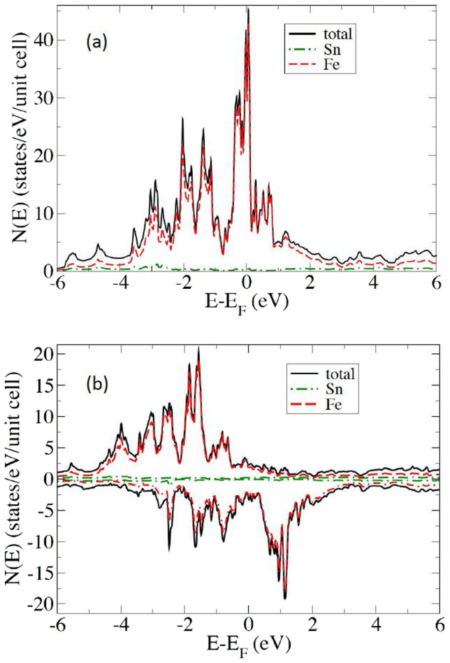
Electronic structure calculations of Fe3Sn have not been previously reported. In Figure 1 we present the calculated electronic density of states of Fe3Sn in the non-magnetic and ferromagnetic states. The plots show the expected characteristics of a Stoner ferromagnet, similar to Fe, specifically a high Fe d density of states at the Fermi level without moment formation, which is then strongly reduced by the exchange splitting in the ferromagnetic phase. The non-spin-polarized value is N(EF) = 29.05 states/eV-unit cell, or 4.8 states/eV on a per Fe basis. The Stoner criterion (NI > 1, with N = N(EF)/2 = 2.4 eV−1 to place it on a per spin basis, and I ~ 1 eV for 3d transition elements) is clearly satisfied. The calculated exchange splitting is ~2.5 eV, based on the spin-polarized density of states. Thus the basic physics of the moment formation is similar to the well-established understanding of bcc Fe.
Figure 1. The calculated densities-of-states of Fe3Sn in the non-magnetic state (a) and in the ferromagnetic state (b).
As virtually all the DOS character near EF is from Fe d-states, it is instructive to compare certain of the results to those computed for elemental Fe. In particular, the calculated local moment on Fe in Fe3Sn, at 2.41 μB, is significantly greater than the corresponding value for Fe (2.25 μB). In addition, the calculated total (i.e. spin-up + spin-down) magnetic DOS for Fe3Sn is 0.78 states/eV-Fe atom (note that the unit cell contains 6 Fe), while the corresponding value for pure Fe is 1.11 states/eV-Fe atom. These facts together suggest that the moment formation in Fe3Sn is in some sense stronger than in Fe although the Curie temperature is lower than that of Fe. This is consistent with reduced effective coordination in the Fe3Sn structure, which in general gives narrower bands, and thus higher moments, and at the same time reduced effective exchange couplings and therefore Curie temperatures. In bcc Fe, there are eight nearest neighbors at 2.48 Å distance, while in Fe3Sn each of the six equivalent Fe atoms has two Fe nearest neighbors at 2.49 Å and four more Fe at 2.61 Å. Note also that the nearest Sn atom is at a distance of 2.73 Å. This reduced effective coordination in a uniaxial structure also favors orbital moment formation and anisotropy on the Fe site. Our calculated Fe orbital moment is 0.073 μB per Fe for Fe3Sn.
Returning to the role of Sn, as mentioned p-electrons in principle can yield stronger effects than d- or f-electrons provided that a moment is induced in the p-electron atom. In the present case, the states near EF are almost entirely derived from Fe d-electrons. Magnetocrystalline anisotropy comes from the spin orbit interaction. We repeated the calculations of the anisotropy for Fe3Sn with spin-orbit removed on the Sn site (but left intact on the Fe site). We find that in spite of the fact that almost all the magnetization comes from Fe, Sn does contribute a non-negligible amount to the anisotropy. The value of K1 is reduced by ~15% to 1.36 MJ/m3 when spin-orbit is removed on the Sn site.
Experimental Results
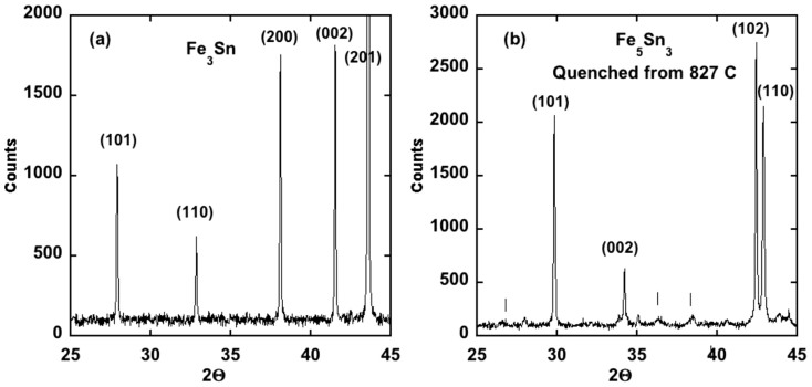
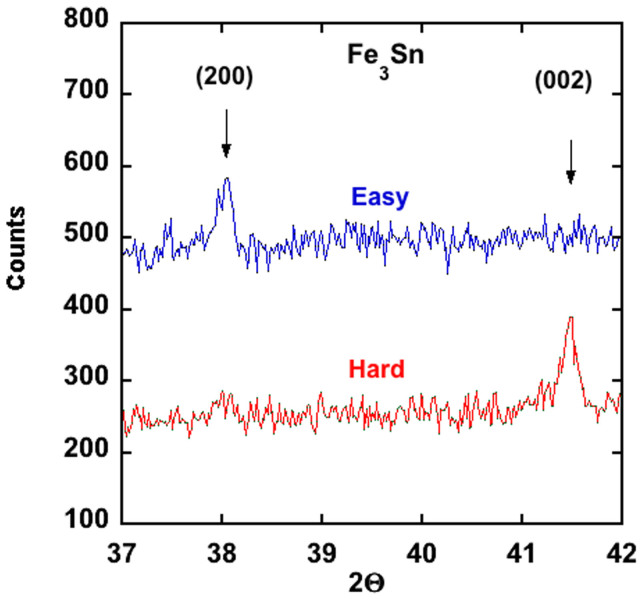
A portion of the powder x-ray diffraction pattern from a polycrystalline Fe3Sn sample and a Fe5Sn3 sample are shown in Figure 2. The Fe3Sn phase is at least 95% single phase, and the crystal structure can be described by the hexagonal Ni3Sn structure7 with the lattice constants given in Table 2. To assess the magnitude of the magnetic anisotropy energy, and the easy axis of magnetization for Fe3Sn, powder of Fe3Sn was dispersed in a clear non-magnetic epoxy inside a gelcap and exposed to a 4 Tesla magnetic field until the epoxy had hardened. A powder x-ray diffraction pattern from the oriented powder confirmed the theoretical prediction that the magnetic easy axis is in the basal plane and not along the c axis as concluded by Trumpy6 based on Mossbauer data. To further confirm this conclusion the two-rotation method was used to orient Fe3Sn powder so that the magnetically hard axis lay along the cylindrical axis of the gelcap. As expected, powder x-ray diffraction data (Figure 3) showed that the hard axis is along c (i.e. the easy axis is in the basal-plane).
Figure 2. Powder x-ray diffraction patterns from (a) Fe3Sn and (b) an Fe5Sn3 sample that was quenched from 827°C.
The vertical lines in (b) correspond to superlattice reflections. Note that for the pure Fe3Sn phase the (200) and (002) reflections have similar intensity in an unoriented powder.
Table 2. Crystallographic properties of several Fe-Sn based alloys. The quench temperatures for the Fe5Sn3 compounds are shown in parenthesis. For the Fe5Sn3 crystal, crystallographic data for the Ni2In-type subcell is shown. See Supplemental Material for details of the orthorhombic structure.
| Composition | a (Å) | c (Å) | c/a | Cell Volume (Å3) |
|---|---|---|---|---|
| Fe3Sn | 5.4624 | 4.3544 | 0.7972 | 112.52 |
| Fe2.5Mn0.5Sn0.95Sb0.05 | 5.4795 | 4.3669 | 0.7969 | 113.55 |
| Fe2.5Mn0.5Sn | 5.4763 | 4.3636 | 0.7868 | 113.33 |
| Fe1.5Mn1.5Sn0.9Sb0.1 | 5.5310 | 4.4175 | 0.7987 | 117.03 |
| Fe1.5Mn1.5Sn0.85Sb0.15 | 5.5325 | 4.4192 | 0.7988 | 117.17 |
| Fe5Sn3 (1100 K) | 4.2187 | 5.2464 | 1.2436 | 80.86 |
| Fe5Sn3 (1155 K) | 4.2247 | 5.2355 | 1.2393 | 80.925 |
| *Fe5Sn3 Crystal (hexagonal Ni2In-type subcell-) T = 173 K | 4.2063 | 5.242 | 1.2464 | 80.34 |
Figure 3. Powder x-ray diffraction data from magnetic-field-oriented Fe3Sn powder dispersed in a clear epoxy.
A field of 4 Tesla is applied along the gelcap axis until the epoxy hardened. The x-ray data unambiguously identifies the easy magnetic axis in the basal plane, which is detrimental for a potential permanent magnet, and in contradiction to the conclusion of Trumpy et al6. based on a less direct method (Mossbauer data).
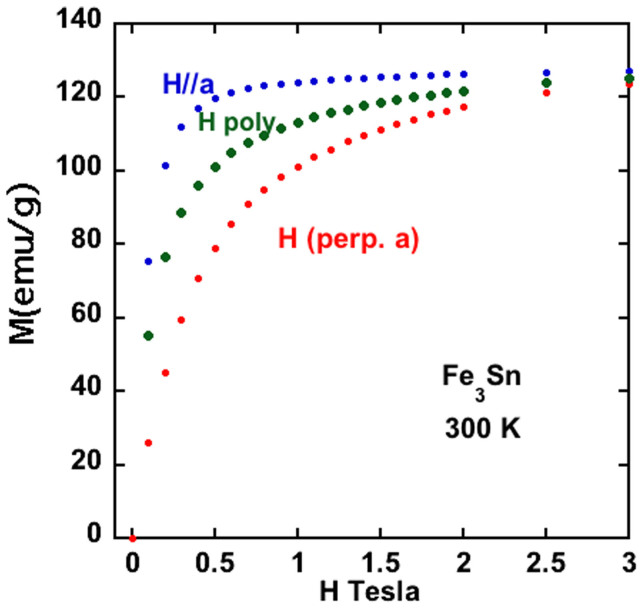
A rough estimate of the anisotropy energy, K1, can be obtained from a comparison of magnetization curves from Fe3Sn powder oriented along the easy and hard directions. These data are shown in Figure 4. Using the approximation that K1 ≈ HaMs/2, with Ha ≈ 3 Tesla (the field at which the magnetization curves along the easy and hard directions merge), Ms = 1.18 MA/m yields 1.8 MJ/m3. The experimental magnitude of K1 is reasonably large but has the wrong sign (easy axis in plane rather than along c). Magnetization data versus temperature (300-2 K) from polycrystalline Fe3Sn in various applied magnetic fields (not shown) gave no indication of a change of the easy axis with temperature. This experimental estimate of K1 is remarkably close to the theoretical prediction of 1.59 MJ/m3 given above.
Figure 4. Magnetization versus applied field for oriented Fe3Sn powder, and a polycrystalline Fe3Sn sample.
Using the x-ray density of Fe3Sn, the room temperature saturation moment is 1.18 MA/m, or about 2.37 μB/Fe. Noting that the magnetization curves merged together near 3 Tesla, indicates a value for K1 of about 1.8 MJ/m.
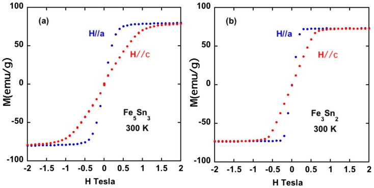
A planar easy axis was also found for the Fe5Sn3, and Fe3Sn2 phases using single crystals (Figure 5), although for Fe3Sn2 there is not much difference in energy between spin directions. We note that these room temperature results (planar easy axis) for Fe3Sn2 disagree with older data reported for polycrystalline samples10,11.
Figure 5. Magnetization versus magnetic field for single crystals of (a) Fe5Sn3 and (b) Fe3Sn2.
The data for Fe5Sn3 crystals (a), which grow as needles, has been corrected for demagnetization effects. The Fe3Sn2 crystals grow as hexagonal plates, and these data (b) have not been corrected for demagnetization. For Fe3Sn2, at least half of the difference in magnetization at low fields between H//a and H//c is due to the shape of the crystal.
The magnetic anisotropy energy (MAE) is a small energy (≈1 meV/atom) that often can be manipulated through alloying. As described previously, the effects of various chemical substitutions on the MAE were first calculated from first principles. The calculated results of some of the substitutions on the both the sign and the magnitude of the MAE are shown in Table 1. These calculations indicate, for example, that replacing 25% percent of the Sn with Sb should flip the easy axis from planar to uniaxial.
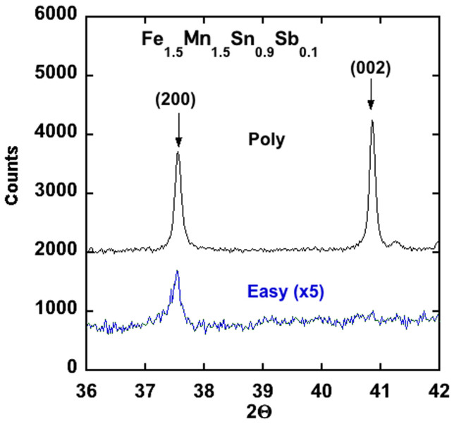
Based on this theoretical guidance a variety of Fe3Sn alloys with compositions Fe3−xMxSn1−yAy, where M = Co, Mn and A = Sb, As, Bi, Pb were prepared and evaluated. The substitution of a small amount of Sb (y < 0.1) to the Fe3Sn structure resulted in the destabilization of the desired phase and the formation of the Fe5Sn3 structure and a Fe0.96Sn0.04 alloy, with some Sb going into the Fe5Sn3 phase (Figure 6). Similar results were obtained with the substitution of Co or As, while virtually no Pb or Bi could be substituted into any of phases containing iron. Only Mn could be readily substituted into the Fe3Sn phase, as also was known from a previous report on the properties of Mn rich alloys (x > 1.5) with the Fe3Sn structure12. All of the dopants investigated, except Mn, add electrons to the Fe3Sn structure, which suggest that perhaps other dopants, like Sb, could be substituted for Sn if part of the Fe is replaced by Mn. Indeed, this was found to be the case and up to ≈15% Sb could be substituted for Sn by co-doping with Mn (Figure 6). However, the substitution of large amounts of Mn (x = 1.5) lowered both the Curie temperature and the saturation moment (Table 3). Although the anisotropy energy of the co-doped alloys is less than pure Fe3Sn, it still has the undesired basal plane anisotropy (Figure 7).
Figure 6. Powder x-ray diffraction data from Fe3Sn doped with various elements.
Adding a small amount of Sb (a) or Co (b) results in a destabilization of the Fe3Sn phase in favor of the Fe5Sn3 phase and a Fe-Sn alloy with approximate composition Fe0.96Sn0.04. Up to 15% Sb can be substituted for Sn in the Fe3Sn structure if part of the Fe is replaced by Mn. (c)
Table 3. Magnetic properties of several Fe-Sn based alloys. The anisotropy energy, K1, was estimated using the approximation K1 ≈ HaMs/2. The quench temperatures for the Fe5Sn3 compounds are shown in parenthesis.
| Composition | Tc (K) | Ms (μB/Fe-Mn) (300 K) | Ms (300 K (emu/g) | Ms (300 K) (MA/m) | Ms (5 K) (MA/m) | K1(est.) (MJ/m3) |
|---|---|---|---|---|---|---|
| Fe3Sn | 725 | 2.37 | 138 | 1.18 | 1.23 | 1.8 |
| Fe2.5Mn0.5Sn0.95Sb0.05 | 645 | 2.08 | 122 | 1.02 | 1.11 | 1.15 |
| Fe1.5Mn1.5Sn0.9Sb0.1 | 405 | 1.42 | 83 | 0.68 | 0.91 | >0 |
| Fe1.5Mn1.5Sn0.85Sb0.15 | 405 | 1.35 | 79 | 0.65 | 0.90 | >0 |
| Fe5Sn3 (1100 K) | 605 | 1.84 | 81 | 0.70 | 0.77 | -- |
| Fe5Sn3 (1155 K) | 635 | 1.97 | 87 | 0.75 | 0.83 | -- |
| Fe5Sn3 Crystal (1100 K) | 620 | 1.84 | 81 | 0.70 | 0.77 | 0.35 |
Figure 7. Powder x-ray diffraction data from polycrystalline Fe1.5Mn1.5Sn0.9Sb0.1 and field aligned powder, showing that the easy magnetic axis is still in the plane.
Conclusions
Although Fe3Sn has many of the desirable properties for a permanent magnet phase, the easy axis of magnetization at room temperature is in the hexagonal plane and remained so for all of the experimentally investigated chemical substitutions. Theory predicts, however, that uniaxial anisotropy can be achieved by certain substitutions specifically, alloying Sb on the Sn site. It will be of interest to study this material to determine whether a related alloy with significant (~25% or greater) Sb substitution can be found and if this is feasible to study the magnetic properties of such material.
Methods
Synthesis
All of the alloys with the Fe3Sn type structure were prepared by solid-state reaction. Powders of Sn and Fe of the appropriate weights were ground together, pressed into a pellet and sealed under vacuum in a silica ampoule. Upon the first firing, the pressed pellets were heated to 805 C at 2°C/min and held for 2 days and then quenched into water. The pellets were reground and then loaded into a furnace that was preheated to 805 C, left for another 2–3 days and then quenched into water. All alloys of the Fe3Sn phase (e.g. Fe1.5 Mn1.5 Sn0.9 Sb0.1) were prepared in the same way. Single crystals (mm size) of Fe3Sn2 and Fe5Sn3 could be grown out of excess Sn using the phase diagram published in reference 7,13,14. The Fe3Sn2 crystals grew as mm sized hexagonal plates, while the Fe5Sn3 crystals grew as needles. Powders of Fe-Sn compounds were prepared by thoroughly grinding the pellets by hand in an agate mortar and pestle. The powder used was passed through a 400 mesh, which corresponds to particles less than 37 micron in size. A few milligrams of the sieved powder were stirred into a clear epoxy (Hardman 04004, setting time 1 h) that was held inside a cylindrical gelatin capsule. The capsule then was placed in a 4T field that was applied along the cylindrical axis of the capsule and the epoxy allowed to set. Each particle was essentially a single crystal grain and the particles were aligned by the field with the easy direction along the long axis of the capsule. X-ray measurements from the aligned powder indicated a planar easy axis (easy direction of magnetization in hexagonal plane). To determine the field necessary to move the magnetization from the easy plane to the hard c axis a capsule was again filled with a few milligrams of powder and epoxy. The capsule was oriented with the cylindrical axis of the capsule perpendicular to the applied field of 4T. After about 20–30 minutes the capsule was rotated by 90° about the cylindrical axis in the 4T field. The long axis of the capsule remained perpendicular to the field. After the epoxy hardened, the field was set to zero and the capsule removed from the cryostat. After these steps, the c axis of most of the powder grains were aligned along the long axis of the capsule. For more details, see reference 15.
Characterization
Powder x-ray diffraction measurements were performed with a PANalytical X'Pert diffractometer and a position sensitive detector using monochromated Cu Kα1 radiation. Single crystal X-ray diffraction measurements on Fe5Sn3 crystals were performed on a Bruker SMART APEX CCD-based single crystal X-ray diffractometer with Mo Kα radiation. (Additional information about the single crystal data collection and refinement process is given in the supplementary information). A Quantum Design Magnetic Property Measurement System (MPMS) was used for magnetic measurements. Because of the large magnetic signal from the ferromagnets, the typical sample mass was restricted to less than 10 mg. The sample weights were measured carefully using a balance with a sensitivity of 0.01 mg. The Curie temperatures of the ferromagnets were determined using the furnace option of the MPMS and a measuring field of 100 Oe.
Theoretical
Our calculations for Fe3Sn were done using LAPW sphere radii of 2.41 Bohr for Sn and 2.35 Bohr for Fe. The internal atomic coordinates relaxed until Hellman-Feynman forces were less than 2 mRyd/Bohr. Spin-orbit coupling was included for all calculations, excepting this structure optimization. Well converged basis sets based on a cut-off RKmax of 9.0 were employed, with as many as 240,000 k-points in the full Brillouin zone used for the calculations of magnetocrystalline anisotropy energy (MAE). Convergence with respect to k-point sampling was carefully checked and variations in MAE at the largest mesh used were no more than a few percent. Orbital moments were also computed. These were approximately 0.073 μB per Fe and a much smaller value for Sn.
Author Contributions
B.C.S. conceived the experiments, prepared all of the samples, and made all of the magnetic measurements and analysis. M.A.M. and B.S. did all of the detailed crystallography measurements and analysis. D.J.S. and D.S.P. did all of the theoretical calculations. B.C.S. wrote the first draft of the paper, and all authors contributed to improving the manuscript.
Supplementary Material
Ferromagnetism of Fe3Sn and Alloys
Acknowledgments
This research was supported by the Critical Materials Institute, an Energy Innovation Hub funded by the U.S. Department of Energy, Office of Energy Efficiency and Renewable Energy, Advanced Manufacturing Office. MAM. acknowledges support of the U.S. Department of Energy, Office of Energy Efficiency and Renewable Energy, Vehicle Technologies, Propulsion Materials Program.
References
- Buschow K. H. J. New developments in hard magnetic materials. Rep. Prog. Phys. 54, 1123–1213 (1991). [Google Scholar]
- Herbst J. F. R2Fe14B materials: Intrinsic properties and technological aspects. Reviews of Modern Physics 63, 819–898 (1991). [Google Scholar]
- Coey J. M. D. Hard Magnetic Materials: A Perspective. IEEE Transactions on Magnetics 47, 4671–4681 (2011). [Google Scholar]
- Givord D., Li H. S. & Perrier de al Bathie R. Magnetic Properties of Y2Fe14B and Nd2Fe14B Single Crystals. Solid State Commun. 51, 857–860 (1984). [Google Scholar]
- Jannin C., Michel A. & Lecocq P. Magnetism and Properties of Different Phases in the Fe-Sn System. Comptes Redus Hebomadaires Seances Acad. Sci. 257, 1906–1907 (1963) [Google Scholar]
- Trumpy G., Both E., Djega-Mariadassou C. & Lecocq P. Mossbauer-Effect Studies of Fe-Sn Alloys. Phys. Rev. B. 2, 3477–3490 (1970). [Google Scholar]
- Giefers H. & Nicol M. High pressure X-ray diffraction study of all Fe-Sn intermetallic compounds and one Fe-Sn solid solution alloy. J. of Alloys and Compounds, 422, 132–144 (2006). [Google Scholar]
- Perdew J. P., Burke K. & Ernzerhof M. Generalized gradient approximation made simple. Phys. Rev. Lett. 77, 3865–3868 (1996). [DOI] [PubMed] [Google Scholar]
- Blaha P. et al. WIEN2k, An Augmented Plane Wave + Local Orbitals Program for Calculating Crystal Properties (K. Schwarz, Techn. Univ. Wien, Austria (2001). [Google Scholar]
- LeCaer G., Malaman B. & Roques B. Mossbauer-Effect Study of Fe3Sn2. J. Phys. F.:Metal Physics 8, 323–336 (1978). [Google Scholar]
- Malaman B., Fruchart D. & LeCaer G. Magnetic properties of Fe3Sn2;II. Neutron diffraction study. J. Phys. F.: Metal Physics 8, 2389–2399 (1978). [Google Scholar]
- Kouvel J. S. Long-Range Magnetic Order in the Mixed Intermetallic Compounds, (Mn, Fe)3Sn. J. Appl. Phys. 36, 980–981 (1965). [Google Scholar]
- Kanatzidis M. G., Pottgen R. & Jeitschko W. The Metal Flux: A Preparative Tool for the Exploration of Intermetallic Compound. Angewandte Chemie. 44, 6996–7023 (2005). [DOI] [PubMed] [Google Scholar]
- Canfield P. C. & Fisk Z. Growth of Single Crystals from Metallic Fluxes. Phil. Mag B. 65, 1117–1123 (1992). [Google Scholar]
- Zuev Y. L. et al. Aligned crystallite powder of NdFeAsO0.86F0.14: Magnetic hysteresis and penetration depth. Phys. Rev. B. 79, 224523 (2009). [Google Scholar]
Associated Data
This section collects any data citations, data availability statements, or supplementary materials included in this article.
Supplementary Materials
Ferromagnetism of Fe3Sn and Alloys


