

The outcome of irreversible electroporation ablation is substantially affected by tissue properties and structure, the local environment, and the orientation of the electrodes.
Abstract
Purpose
To study the effects of the surrounding electrical microenvironment and local tissue parameters on the electrical parameters and outcome of irreversible electroporation (IRE) ablation in porcine muscle, kidney, and liver tissue.
Materials and Methods
Animal Care and Use Committee approval was obtained, and National Institutes of Health guidelines were followed. IRE ablation (n = 90) was applied in muscle (n = 44), kidney (n = 28), and liver (n = 18) tissue in 18 pigs. Two electrodes with tip exposure of 1.5–2 cm were used at varying voltages (1500–3000 V), pulse repetitions (n = 70–100), pulse length (70–100 µsec), and electrode spacing (1.5–2 cm). In muscle tissue, electrodes were placed exactly parallel, in plane, or perpendicular to paraspinal muscle fibers; in kidney tissue, in the cortex or adjacent to the renal medulla; and in liver tissue, with and without metallic or plastic plates placed 1–2 cm from electrodes. Ablation zones were determined at gross pathologic (90–120 minutes after IRE) and immunohistopathologic examination (6 hours after) for apoptosis and heat-shock protein markers. Multivariate analysis of variance with multiple comparisons and/or paired t tests and regression analysis were used for analysis.
Results
Mean (± standard deviation) ablation zones in muscle were 6.2 cm ± 0.3 × 4.2 cm ± 0.3 for parallel electrodes and 4.2 cm ± 0.8 × 3.0 cm ± 0.5 for in-plane application. Perpendicular orientation resulted in a cross-shaped zone. Orientation significantly affected IRE current applied (28.5–31.7A for parallel, 29.5–39.7A for perpendicular; P = .003). For kidney cortex, ovoid zones of 1.5 cm ± 0.1 × 0.5 cm ± 0.0 to 2.5 cm ± 0.1 × 1.3 cm ± 0.1 were seen. Placement of electrodes less than 5 mm from the medullary pyramids resulted in treatment effect arcing into the collecting system. For liver tissue, symmetric 2.7 cm ± 0.2 × 1.4 cm ± 0.3 coagulation areas were seen without the metallic plate but asymmetric coagulation was seen with the metallic plate.
Conclusion
IRE treatment zones are sensitive to varying electrical conductivity in tissues. Electrode location, orientation, and heterogeneities in local environment must be considered in planning ablation treatment.
© RSNA, 2013
Introduction
Irreversible electroporation (IRE) is an image-guided ablation modality that uses an electrical field without thermal energy to induce cell damage, and ultimately, cell death (1,2). Interest in IRE clinical application is increasing, especially for use in locations where thermal damage is a substantial concern, such as the pancreas (3,4) or near vital structures such as the bile ducts in the liver (2). Given that it is less sensitive to inherent tissue characteristics such as vascular heat-sink effects that limit the efficacy of thermal ablation modalities that use radiofrequency, microwave, or cryotherapy (5–7), IRE holds promise for effective treatment of tumors adjacent to blood vessels (8).
Recent studies have shown that IRE is capable of achieving an ablation zone of predictable and clinically significant size in normal, relatively uniform, in vivo porcine liver tissue (5,9). This predictability, compared with that of radiofrequency ablation, has been attributed, at least in part, to the lack of perfusion-mediated tissue cooling. Yet, as early studies of radiofrequency ablation have shown (10), tissue characteristics such as electrical conductivity may also influence IRE application, with effects on ablation shape and size that have not been completely characterized (11,12). Thus, because IRE is now being applied experimentally and clinically in a wide range of tissue including the kidney (13,14), pancreas (3,4), muscle, and soft tissue (15,16), the variability in ablation outcome among different, clinically relevant tissues with diverse physical and electrical properties must be identified. Accordingly, we hypothesized that IRE ablation may be sensitive to multiple variables that effect the electrical field distribution, causing a discrepancy between current prediction algorithms for ablation area and the final zone of treatment.
Our purpose was to study the effects of the surrounding electrical microenvironment and local tissue properties on the electrical parameters, ablation zones, and outcome of IRE ablation by using various methods of IRE application in muscle, kidney, and liver tissue.
Materials and Methods
Support for this study was provided by RITA/Angiodynamics (Fremont, Calif). All authors were members of the Applied Radiology Research Laboratory in the Department of Radiology of Hadassah Hebrew University Medical Center (Jerusalem, Israel) or the Minimally Invasive Tumor Therapy Laboratory at Beth Israel Deaconess Medical Center (Boston, Mass) and had complete and independent control of study data gathering, data analysis, and manuscript preparation.
Animal Model
Approval for the use of the animal model of this study was obtained from the Animal Care and Use Committees of the Hebrew University and in accordance with National Institutes of Health guidelines.
To enable direct comparison, 18 female Yorkshire swine (weight range, 85–100 kg; Lahav, Israel) were studied by using techniques similar to those used in previous reports (9,17). The study was performed by a team (S.N.G., A.W., M.F., E.B.D, I.N., with more than 5 years of experience) who worked together on this experimental ablation model. A detailed description of these procedures is available in the Appendix E1 (online).
All electrodes were placed with ultrasonographic guidance (MyLab70XVG; Esaote, Genova, Italy). Electrodes in the muscle were placed percutaneously with ultrasonographic documention of intraelectrode spacing within 2 mm of the stated target interelectrode spacing. Open surgical technique was used to access the liver and kidney and to allow accurate spacing of the IRE electrodes within 2 mm of the stated target in regions of solid parenchyma that were relatively free of vessels greater than 3 mm in diameter.
IRE Ablation System
Electroporation was induced by using two monopolar 18-gauge electrodes (Angiodynamics, Fremont, Calif) of variable tip exposure (1.5 cm for kidney and 2 cm for muscle and liver) and interelectrode spacing (1.5 cm and 2 cm), which were connected to an electroporation generator (Nanoknife, Angiodynamics). Energy was applied on the basis of prior optimization studies (9) at 1500–3000 V (pulse length, 70, 90, and 100 μsec; pulse repetition, 70, 90, and 100) at the R wave of the cardiac cycle.
Experimental Design
Experiments were performed in three different types of tissue: paraspinal muscle (n = 44), kidney (n = 28), and liver (n = 18) for a total of 90 ablations in 18 pigs.
In the muscle, IRE was applied to two electrodes with 2-cm tip exposure at four defined voltages from 1500 to 2400 V with 1-, 1.5-, and 2-cm interelectrode spacing at 70, 90, or 100 pulses of 70, 90, or 100 µsec per pulse. To investigate the effect of electrode orientation relative to tissue and cell orientation on final ablation results, the electrodes were placed in three different orientations relative to muscle fibers: perpendicular (n = 12), in plane (n = 27), or exactly parallel (n = 5) (Fig 1). Parallel placement was facilitated by arching the pig’s back and taking advantage of the conspicuity of the muscle fiber direction at ultrasonography.
Figure 1:

Schematic of IRE electrode placement in muscle. Exactly parallel (A), in plane (B), and perpendicular (C) orientations are shown.
To determine the effect of regional anatomic variations in the kidney, the two electrodes were either placed in the peripheral renal cortex (n = 22) or adjacent to the medulla (n = 6). IRE was applied throughout a range of clinically relevant energy settings (voltage, 2000–3000 V; pulses, 70, 90, and 100; pulse length, 70, 90, and 100 µsec per pulse) for two electrodes, with a 1.5-cm active electrode tip exposure and interelectrode spacing of 1, 1.5, and 2 cm.
In the liver, IRE was applied to electrode pairs with 2-cm active electrode tip exposure and 1.5-cm interelectrode spacing placed in the parenchyma at standardized clinically relevant IRE parameters of 2250 V for 90 pulses of 70 µsec per pulse (n = 18). To assess regional changes in electrical conductivity, the tissue environment was altered by placing external 10 × 15 cm metallic grounding plates within 1–2 cm of the active portion of the electrodes on the superior (n = 5) or inferior (n = 5) liver surface. The size and position of the ablation were compared with equivalent IRE application performed with (n = 3) and without (n = 5) a plastic (ie, nonconductive) plate placed similarly on the liver surface.
Finally, treatment effect on tissue electrical conductivity was calculated by taking advantage of the voltage constant system. Initially, baseline electrical currents were derived by measuring the current of the first 10 IRE pulses at 2250 V in all three tissues. These values were then compared with the current measured during the final 10 IRE pulses to determine the extent of any intraprocedural current changes.
Pathologic Examination
Most of the animals (n = 17, 83 ablations) were sacrificed at 90–120 minutes after the last IRE application to enable adequate visualization of the gross and histopathologic treatment effect (18). To determine immunohistochemical findings, an additional seven specimens of ablated tissue were harvested from one animal at 6 hours after IRE (19). Representative sections of all tissues were stained by using hematoxylin-eosin. Immunohistochemical analysis included staining for heat shock protein formation (HSP-70) and for an apoptosis marker (cleaved caspase-3) and further analyzed at histopathology. For muscle, representative sections were also stained for 15 minutes in 1% nitro-blue tetrazolium (NBT\BCIP 1-Step Solution; Thermo Scientific Pierce, Rockford, Ill) to demonstrate mitochondrial activity.
Data Analysis and Statistical Analysis
Gross pathologic specimens were characterized and measured. Data collection and analysis were performed by five authors (I.N., S.N.G., E.B.D., M.F., and A.W.), and statistical analysis was performed by two authors, (S.N.G. and E.B.D.).
Data were analyzed by using multivariate analysis of variance when multiple comparisons were present, with repeated measurement of paired Student t tests for specific comparisons for P values was less than .05 by using analytic software (version 8.2, SAS; SAS Institute, Cary, NC or Excel; Microsoft, Redmond, Wash).
Results
Muscle
At generator output of 2000 V, the greatest ablation zones were achieved when IRE electrodes were placed exactly parallel to the muscle fibers (Fig 2a, Table 1). The cross-sectional measurement of the ablation zones was 6.2 cm ± 0.3 × 4.2 cm ± 0.3, and length measurement was 5.0 cm ± 0.1, compared with 4.2 cm ± 0.8 × 3.0 cm ± 0.5 cross-sectional measurement with these settings for in-plane treatment (P = .013 and .001 for width and depth, respectively).
Figure 2a:
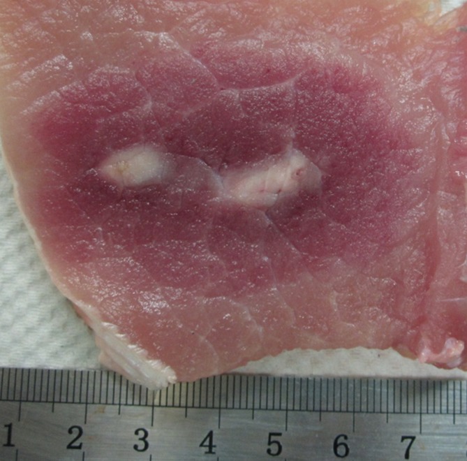
Photographs of treated muscle at gross pathologic examination show ablation shape. (a) Insertion of electrodes exactly parallel to the muscle fibers produced the largest cross-sectional ablation zone (6.2 cm ± 0.3 × 4.2 cm ± 0.3 for 90 pulses, 70 µsec per pulse at 2000 V). Comparison of (b) in-plane versus (c) perpendicular orientation ablation for similar IRE parameters shows smaller but symmetric zone of 4.2 cm ± 0.8 × 3.0 cm ± 0.5 for b but a cross-shaped ablation zone for c.
Table 1.
Comparison of Selected Parameters in Muscle
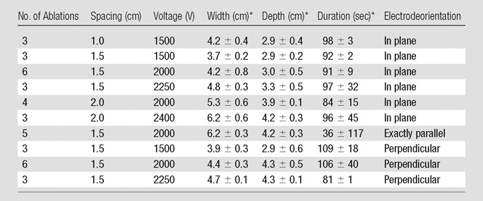
Data are means ± standard deviation
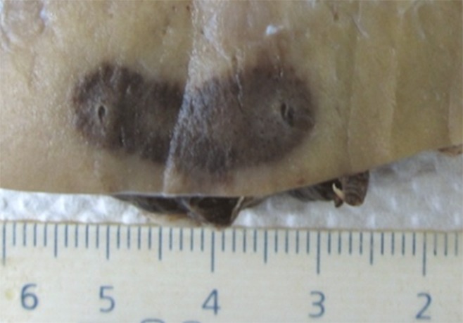
Cross-sectional ovoid zones of ablation were also achieved for most applications when the IRE electrodes were placed in plane with the muscle fibers (Fig 2b), with multivariate analysis of variance showing increasing overall cross-section size and central white coagulation noted for increasing energy and interelectrode spacing (Table 1, P = .01). At the lowest energy settings (1500 V) a bilobed, figure-eight shape was seen at gross pathologic examination for in-plane electrode insertion (Fig 3) in addition to 2.7 cm ± 0.3 × 2.1 cm ± 0.1 zones of white coagulation in the center of the ablation. Placing the IRE electrodes perpendicular to the muscle fibers resulted in a cross-shaped ablation area at all voltages studied (Table 1, Fig 2c).
Figure 2b:

Photographs of treated muscle at gross pathologic examination show ablation shape. (a) Insertion of electrodes exactly parallel to the muscle fibers produced the largest cross-sectional ablation zone (6.2 cm ± 0.3 × 4.2 cm ± 0.3 for 90 pulses, 70 µsec per pulse at 2000 V). Comparison of (b) in-plane versus (c) perpendicular orientation ablation for similar IRE parameters shows smaller but symmetric zone of 4.2 cm ± 0.8 × 3.0 cm ± 0.5 for b but a cross-shaped ablation zone for c.
Figure 3:
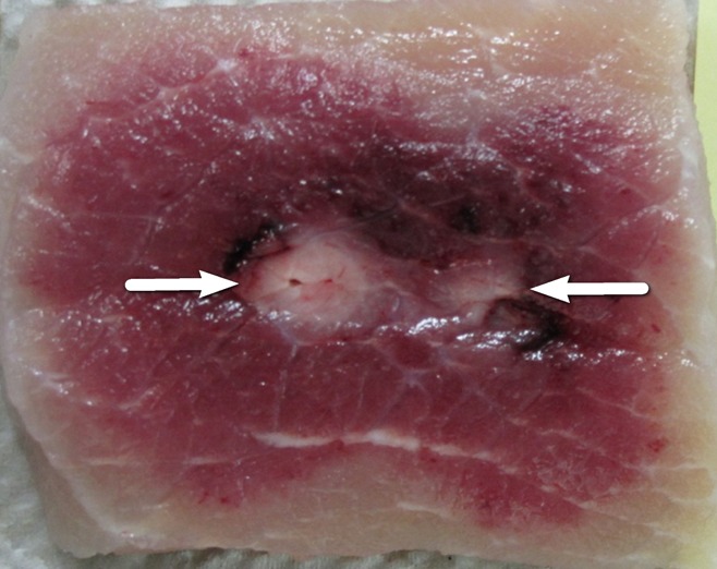
Photograph at gross pathologic examination of a muscle treated with 1500-V IRE, resulting in a bilobed, figure-eight–shaped ablation zone, with central white coagulation (arrows).
Figure 2c:
Photographs of treated muscle at gross pathologic examination show ablation shape. (a) Insertion of electrodes exactly parallel to the muscle fibers produced the largest cross-sectional ablation zone (6.2 cm ± 0.3 × 4.2 cm ± 0.3 for 90 pulses, 70 µsec per pulse at 2000 V). Comparison of (b) in-plane versus (c) perpendicular orientation ablation for similar IRE parameters shows smaller but symmetric zone of 4.2 cm ± 0.8 × 3.0 cm ± 0.5 for b but a cross-shaped ablation zone for c.
The red peripheral area of IRE ablation had condensed wavy muscle fibers that often contained vacuoles (Fig E1a [online]). Widened fluid-filled spaces were shown between these fibers. In the white central zone, typical coagulation necrosis (pyknotic nuclei and streaming cytoplasm) were seen (Fig E1b [online]). Both areas of treatment did not stain positively for cleaved caspase-3 or HSP-70 (Fig E1c, E1d [online]). Nitro-blue tetrazolium staining 1.5 hours after IRE application demonstrated viability of the surrounding untreated tissue up to but not including the margins of the red peripheral area of the IRE ablation (Fig 4).
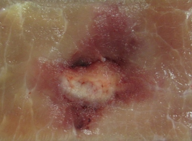
Figure 4:

Photograph at gross pathologic examination with nitro-blue tetrazolium staining shows uptake to the peripheral border of the treatment zone, indicating viable tissue surrounding but not extending into this zone.
Kidney
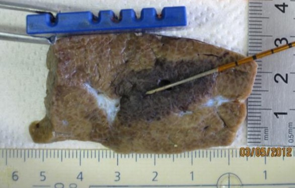
IRE ablation in the polar regions of the peripheral renal cortex produced a relatively ovoid ablation zone in cross section (Fig 5a) for all voltages greater than 2500 V. Ablation areas ranged from 1.5 cm ± 0.1 × 0.5 cm ± 0.0 to 2.5 cm ± 0.1 × 1.3 cm ± 0.1 at 1–1.5 cm interelectrode spacing and energy settings of 2000–3000 V (Table 2). Bilobed or separate ablation zones were seen for lower voltages and/or at interelectrode spacing of 2 cm, even at voltage settings as high as 3000 V. When IRE was applied at the middle pole, the treatment area deviated several millimeters along the contour of the kidney, keeping in plane with the cortex. More pronounced deviations were seen when IRE was applied to more central renal tissue as ablations that involved the cortex consistently produced an irregularly shaped ablation zone with a comma-shaped tail deviating toward or ablating into the collecting systems (Fig 5b).
Figure 5a:
Photographs show gross pathologic examination of IRE treated kidney. (a) Symmetric, ovoid ablation zone shows ablation of peripheral cortex. (b) More centrally positioned ablation zone shows arcing effect of treatment zone toward medulla (arrow). Additional images of gross pathologic examination of kidney are in Figure E2 (online).
Table 2.
Summary of Peripheral and Cortical Renal Ablations

Nonuniform ablation: two separate oval shapes of 1.0 cm × 0.8 cm.
Data are means ± standard deviation, where indicated.
Figure 5b:

Photographs show gross pathologic examination of IRE treated kidney. (a) Symmetric, ovoid ablation zone shows ablation of peripheral cortex. (b) More centrally positioned ablation zone shows arcing effect of treatment zone toward medulla (arrow). Additional images of gross pathologic examination of kidney are in Figure E2 (online).
Histopathologic analysis of the IRE-treated kidney tissue showed widened spaces between nephrons caused in part by shrunken cells (Fig 6a). These widened spaces were filled by 1.5 hours after IRE with peritubular hemorrhage, including that around areas of ablation that were deviated toward the medulla. No cleaved caspase-3 staining was observed in or around the treatment zone (Fig E3 [online]). However, HSP-70 staining outlined the ablation zone clearly at 6 hours with robust expression of this protein in almost every tubule, extending 5–10 mm beyond the treatment zone (Fig 6b).
Figure 6a:

Photomicrographs (×20) of histopathologic and immunohistochemical analysis in IRE-treated porcine kidney. (a) Hematoxylin-eosin (H&E) staining shows peritubular hemorrhage. (b) Positive HSP 70 staining outlines IRE treatment zone.
Figure 6b:
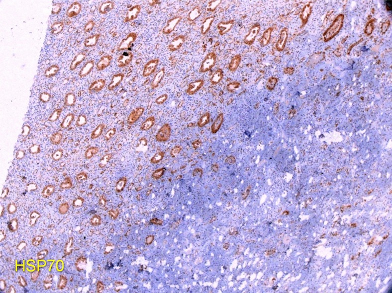
Photomicrographs (×20) of histopathologic and immunohistochemical analysis in IRE-treated porcine kidney. (a) Hematoxylin-eosin (H&E) staining shows peritubular hemorrhage. (b) Positive HSP 70 staining outlines IRE treatment zone.
Liver
IRE ablation to liver resulted in ovoid-shaped zones of treatment that measured 2.7 cm ± 0.2 × 1.4 cm ± 0.3 in all cases. For treatments in which no external modifiers (ie, grounding pads) were present, this zone of ablation centered symmetrically around the electrodes (Fig 7a). However, the placement of metal plates on either the superior or inferior liver surface resulted in a distortion of zone of treatment manifested by a displacement of 0.4 cm ± 0.2 or 0.8 cm ± 0.6 toward the superior or inferior liver surface, respectively (Fig 7b, 7c). Such alteration to the distribution of treatment effect was not seen when a plastic plate was placed on the liver surface within 1.0–2.0 cm of the active electrode because symmetrical ovoid ablation zones were again noted (Fig 7d).
Figure 7a:

Gross pathologic examination of liver IRE ablations with electrode and plates superimposed for demonstration of positioning. (a) IRE application (90 pulses, 70 µsec per pulse at 2250 V) with no plates shows symmetric treatment effect surrounding electrode. Placement of surface metallic plates (b) above and (c) below site of IRE application shows deviation in ablation zone toward (arrow). (d) Plastic plate has no effect on ablation zone.
Figure 7b:
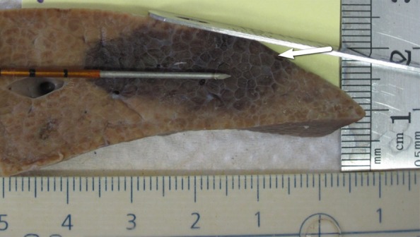
Gross pathologic examination of liver IRE ablations with electrode and plates superimposed for demonstration of positioning. (a) IRE application (90 pulses, 70 µsec per pulse at 2250 V) with no plates shows symmetric treatment effect surrounding electrode. Placement of surface metallic plates (b) above and (c) below site of IRE application shows deviation in ablation zone toward (arrow). (d) Plastic plate has no effect on ablation zone.
Figure 7c:
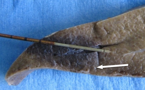
Gross pathologic examination of liver IRE ablations with electrode and plates superimposed for demonstration of positioning. (a) IRE application (90 pulses, 70 µsec per pulse at 2250 V) with no plates shows symmetric treatment effect surrounding electrode. Placement of surface metallic plates (b) above and (c) below site of IRE application shows deviation in ablation zone toward (arrow). (d) Plastic plate has no effect on ablation zone.
Figure 7d:
Gross pathologic examination of liver IRE ablations with electrode and plates superimposed for demonstration of positioning. (a) IRE application (90 pulses, 70 µsec per pulse at 2250 V) with no plates shows symmetric treatment effect surrounding electrode. Placement of surface metallic plates (b) above and (c) below site of IRE application shows deviation in ablation zone toward (arrow). (d) Plastic plate has no effect on ablation zone.
Similar to that in prior reports, IRE-associated abnormality (ie, swollen sinusoid, dehydrated cells, hemorrhagic infiltrate) was observed in all specimens (Fig 8a) (18).Wide bands of cleaved caspase-3–positive apoptotic cells (Fig 8b) were seen at the periphery of the treatment zone, and minimal to no HSP-70 was detected (Fig E4 [online]).
Figure 8a:

Low power (×5) photomicrographs of histopathologic analysis of IRE treatment in porcine liver. (a) Hematoxylin-eosin staining with swollen sinusoids and hemorrhagic infiltrate. (b) Cleaved caspase-3 is seen in the periphery of the treatment.
Figure 8b:

Low power (×5) photomicrographs of histopathologic analysis of IRE treatment in porcine liver. (a) Hematoxylin-eosin staining with swollen sinusoids and hemorrhagic infiltrate. (b) Cleaved caspase-3 is seen in the periphery of the treatment.
Treatment Effect on Tissue Electrical Conductivity
Baseline initial currents varied by tissue type (Table 3), with liver having the lowest current (14.4 A ± 1.9), followed by kidney and muscle with the highest (34.7 A ± 1.5). Furthermore, variations were noted in the organs; renal medulla had greater conductivity (23.0 A ± 4.2) than renal cortex (21.8 A ± 4.4). Likewise, external electrical field modification with metal plates increased current in the liver significantly (P = .048). The change in current after treatment also varied, with liver and kidney showing a decrease in the current, while the muscle tissue current increased. For muscle, electrode orientation had a significant effect on the posttreatment tissue current (Table 4), with perpendicular electrode orientation having greater increase than in-plane or exactly parallel electrode orientation (10.2 A ± 4.2 vs 5.4 A ± 2.7 and 3.2 A ± 1.7, respectively; P = .007).
Table 3.
Tissue Current Comparison for Ablations at 2250 V

Note.—Data are current in amperes. Significant differences were noted for baseline and posttreatment current measurements between different tissues as well as for liver tissue when metal is nearby. Electrical data are the average of the first 10 (baseline) and last 10 (end) pulses.
Table 4.
Electrical Current in Muscle Tissue for Ablations at 2000 V

Note.—Unless otherwise indicated, data are current in amperes. No significant difference was noted in baseline current measurements in the different electrode orientations. However, significant differences were seen in the increased posttreatment current. Electrical data are the average of the first 10 (baseline) and last 10 (end) pulses.
Discussion
Given several perceived advantages, including a largely nonthermal mechanism of action (19), IRE is being studied in a wide range of different organs, including the liver (9,20), pancreas (3,4,21), lung (8,22,23), and kidney (13,14,24). Our study confirms that under many IRE settings, a uniform, symmetrical, geometrically ellipsoid zone of ablation can be produced in normal liver, kidney, and muscle tissue. However, ablation sizes were tissue and/or organ specific, as we demonstrated that the ovoid cross-sectional dimensions can differ, with greatest treatment effect noted for muscle, followed by liver and then kidney. This suggests strongly that, like radiofrequency and other methods of tumor ablation (25–27), tissue composition may alter clinical results, calling for greater study of clinically relevant tissues, including different tumor types.
On the basis of the results reported for thermal tumor ablation (28) and the known symmetrical electrical distribution surrounding a pair of IRE electrodes (29), we anticipated that identical oval-shaped ablation zones would result from a given IRE application, regardless of the orientation of the electrodes. To our surprise, we noted that that, in muscle tissue, electrodes placed orthogonally (ie, perpendicular) to the muscle fibers formed a cross-shaped zone of ablation. In addition, we also noted that larger ovoid ablation zones were seen when the electrodes were placed exactly parallel compared with IRE application to in-plane electrodes with the identical energy parameters. These findings suggest that at least one incompletely characterized local tissue factor influences IRE ablation to a greater extent than that previously noted for radiofrequency or microwave-based systems (10,30). The nature of these changes raises the possibility that a tissue property such as the effect of cell size and/or fiber orientation on electrical conductivity or field generation is responsible for this phenomenon.
Previous studies (13,24) of IRE treatment in in-vivo porcine kidney produced slightly larger ablation zones in the short axis of 1.7–1.9 cm, compared with 1.3 cm seen in our study. Given the use of similar equipment, this discrepancy could be attributed to differences in the orientation of the electrodes. Our protocol enabled us to clearly identify that ablation that abutted or entered into the medulla resulted in a definitive and reproducible effect on the geometry of the ablation zone, extending into the collecting systems. Here too, these effects can be attributed to the heterogeneity of tissue composition and/or electrical conductivity in the kidney with increased local conductivity centrally, particularly implicating the effects of the Loop of Henle countercurrent multiplier system and/or urine on the electrical field. Inability to obtain complete contiguous ablation at 2-cm interelectrode spacing for the kidney tissue even at the highest setting (3000 V) may have been due to such electrical conductivity effects.
Our ablation of liver tissue with or without metallic plates established the importance of electrical conductivity as at least one of the contributing mechanisms and showed that conductive materials can affect the distribution of the electric field. We demonstrated that placing metallic pads 1–2 cm from the electrodes induces asymmetric areas of treatment effect, with a “pull” toward the conducting medium–a phenomenon not seen with nonconducting plastic plates. Beyond its mechanistic importance, this finding has additional substantial clinical ramifications. Our results suggest that in some cases, foreign bodies (prostheses, stents) or even physiologic changes (ascites) bordering the area targeted for ablation may alter the electrical field sufficiently to modify the shape of the treatment zone. In addition, when IRE is performed during open surgery or laparoscopically, adjacent instruments (ie, retractors) could interfere with IRE tumor ablation.
Our results further showed differences in baseline current and changes after treatment seen among the different tissues for a fixed voltage. Thus, our work adds to the growing body of literature (31) documenting local electrical conductivity changes on the basis of the IRE application method and the tissue in question. Here, application of multiple IRE pulses to liver and kidney tissue showed slight decreases in current from a similar baseline, likely due to effects of repetitive depolarization. However, the opposite was seen in muscle, with increases that were in part due to orientation of IRE electrodes. Higher muscle baseline current and changes during treatment may represent use of innate conduction pathways such as the sarcoplasmic reticulum or activation of the extracellular matrix.
Our results were not entirely anticipated from the recent studies that have attempted to characterize electrical conductivity changes during IRE treatment in the kidney (11) and brain (32), including the use of finite element modeling (33). For the kidney, Neal et al noted (11) that electrical current values reached a plateau; whereas, we observed a decrease in current during the course of IRE treatment of the kidney. This discrepancy may be attributed to the difference in study design including our use of more clinically relevant in-vivo tissue with multiple repetitive IRE pulses compared with their treatment of ex-vivo tissue with a single IRE pulse. More research determining precisely when and how electrical changes occur during IRE application and their implication on treatment outcomes must be performed.
Although perfusion-mediated tissue cooling has the greatest effect of the known tissue factors on thermal ablation (25), tissue electrical conductivity has also been identified as a key factor that can affect tissue heating during radiofrequency ablation (28). In particular, increases in tissue electrical conductivity have been associated with increased energy deposition (34), and techniques such as injecting additional agents (such as saline solution) into the ablation zone, either through electrode modification or separately through an adjacent needle, have resulted in significant gains in achievable size of radiofrequency ablation (35,36). Given the potentially greater role that tissue electrical conductivity plays with IRE, similar adjuvant techniques may allow even larger ablation zones than are currently achievable with existing IRE devices. Along these lines, Adenyaju et al (37) reported beneficial effects of increasing tissue electrical conductivity by using saline solution–irrigated IRE probes in a finite element model including an increased thermal tissue profile farther away from the IRE probes. Additional IRE-specific strategies to increase tissue electrical conductivity, such as use of a modified application algorithm with preparatory pulses to the tissue to create a high conductivity field before IRE application are also being studied by using finite element model (12).
Although many of the effects observed can be best attributed to electrical conductivity, conductivity alone does not explain all of the differences noted in our study. Our results further confirmed different pathophysiologic tissue responses to electroporation. Whereas we confirmed prior reports of robust cleaved caspase-3 staining accompanied by limited HSP-70 immunohistochemical staining for the selected IRE dose in the liver (19), no such response was detected in muscle for these two immunohistochemical stains, despite confirmation of absence of mitochondrial activity in much damaged muscle cells by means of nitro-blue tetrazolium staining. In the kidney, similar to the results of prior reports (13,24), hemorrhage infiltrate was seen between loops of Henle centrally with 6-hour immunohistochemical data confirming the gross findings of a well-demarcated ablation including the extent into calyces. Yet, unlike liver and muscle, this was manifested by markedly increased HSP-70 throughout all unablated tissue surrounding the IRE zone. This is concordant with other studies showing increased sensitivity and HSP response of Loops of Henle under environmental stress (38). The known protective effects of HSP-70 could also account in part for smaller treatment zones in the kidney compared with those in the liver. Alternatively or in concert, nephrons may have a higher tolerance to electric fields because of other, yet to be discovered, mechanisms. Finally, the minimal cleaved caspase-3 seen, compared with prior reports of the liver, suggests that IRE damage in the kidney is direct and immediate with little apoptosis.
We acknowledge the limitations of our study, including that it was performed only on three types of normal tissue. Therefore our results may not be representative of other tissue that may be targeted for IRE, such as neoplastic tumors. Indeed, our study raises questions about the degree of predictability for heterogeneous, fibrous, or partially necrotic or cystic tumors. Further correlation of size and shape of the ablation with known electrical conductivities needs to be studied, as well as the possible effect of cell size (39). Systematic study of the influence of size and distance of any highly conductive substance such as metal on IRE field perturbation could also shed further light on potential variability to be seen in such clinical scenarios.
In conclusion, we demonstrate that IRE ablation is highly sensitive to local surroundings and tissue conductivity, both of which influence the outcome of the ablation. Indeed, our study shows that IRE ablation is substantially affected by tissue properties and structure, the local environment, and the orientation of the electrodes. In addition, each tissue responds to IRE treatment differently, including the extent of apoptosis and HSP-70. Thus, further study and understanding are required for this modality.
The challenges facing IRE are in the realm of electrical tissue composition and characteristics. This is in comparison to radiofrequency and microwave ablation, where issues of tissue perfusion play a much more crucial role (26,40). Ultimately, clinical studies may be necessary to determine under which conditions IRE should be used in place of thermal ablative methods.
Advances in Knowledge
■ There are substantial differences in the size of the irreversible electroporation (IRE) ablation zone for a given set of parameters based on the type of tissue ablated.
■ There are differences in tissue response to IRE ablation at a cellular level, such as the degree of sensitivity to electroporation and the proteins expressed.
■ Local tissue characteristics and other causes for electrical field inhomogeneities can substantially influence the shape of IRE ablation zones.
Implications for Patient Care
■ Use of IRE to ablate tumors in different organs may result in different ablation zone sizes for a given set of parameters based on tissue-specific characteristics.
■ Prediction of IRE ablation outcomes will require input of multiple additional variables including electrode orientation in fibrous tissues, tumor histology, and distance from highly electrically conductive materials (eg, prosthesis, metallic stents, urine, and ascites).
APPENDIX
SUPPLEMENTAL FIGURES
Acknowledgments
Acknowledgment
Thank you Aviva Rhein for the illustration.
Received November 21, 2012; revision requested January 22, 2013; revision received March 15; accepted April 4; final version accepted April 29.
From the 2012 RSNA Annual Meeting.
Supported by RITA/Angiodynamics (Fremont, CA).
Funding: This research was supported by the National Institutes of Health (grant RO1 CA112533-01).
Disclosures of Conflicts of Interest: E.B.D. No relevant conflicts of interest to disclose. M.A. No relevant conflicts of interest to disclose. M.F. No relevant conflicts of interest to disclose. M.M. No relevant conflicts of interest to disclose. A.W. No relevant conflicts of interest to disclose. J.S. No relevant conflicts of interest to disclose. L.A. No relevant conflicts of interest to disclose. I.N. No relevant conflicts of interest to disclose. S.N.G. Financial activities related to the present article: institution receive grant from and author received consulting fee or honorarium from Angiodynamics. Financial activities not related to the present article: consultancy and grants/grants pending from Cosman Company. Other relationships: none to disclose.
Abbreviations:
- HSP-70
- heat shock protein formation
- IRE
- irreversible electroporation
References
- 1.Narayanan G. Irreversible electroporation for treatment of liver cancer. Gastroenterol Hepatol (N Y) 2011;7(5):313–316. [PMC free article] [PubMed] [Google Scholar]
- 2.Lee EW, Chen C, Prieto VE, Dry SM, Loh CT, Kee ST. Advanced hepatic ablation technique for creating complete cell death: irreversible electroporation. Radiology 2010;255(2):426–433. [DOI] [PubMed] [Google Scholar]
- 3.Martin RC, 2nd, McFarland K, Ellis S, Velanovich V. Irreversible electroporation therapy in the management of locally advanced pancreatic adenocarcinoma. J Am Coll Surg 2012;215(3):361–369. [DOI] [PubMed] [Google Scholar]
- 4.Charpentier KP, Wolf F, Noble L, Winn B, Resnick M, Dupuy DE. Irreversible electroporation of the pancreas in swine: a pilot study. HPB (Oxford) 2010;12(5):348–351. [DOI] [PMC free article] [PubMed] [Google Scholar]
- 5.Lee YJ, Lu DS, Osuagwu F, Lassman C. Irreversible electroporation in porcine liver: short- and long-term effect on the hepatic veins and adjacent tissue by CT with pathological correlation. Invest Radiol 2012;47(11):671–675. [DOI] [PubMed] [Google Scholar]
- 6.Cannon R, Ellis S, Hayes D, Narayanan G, Martin RC, 2nd. Safety and early efficacy of irreversible electroporation for hepatic tumors in proximity to vital structures. J Surg Oncol 2013;107(5):544–549. [DOI] [PubMed] [Google Scholar]
- 7.Kingham TP, Karkar AM, D’Angelica MI, et al. Ablation of perivascular hepatic malignant tumors with irreversible electroporation. J Am Coll Surg 2012;215(3):379–387. [DOI] [PubMed] [Google Scholar]
- 8.Dupuy DE, Aswad B, Ng T. Irreversible electroporation in a Swine lung model. Cardiovasc Intervent Radiol 2011;34(2):391–395. [DOI] [PubMed] [Google Scholar]
- 9.Ben-David E, Appelbaum L, Sosna J, Nissenbaum I, Goldberg SN. Characterization of irreversible electroporation ablation in in vivo porcine liver. AJR Am J Roentgenol 2012;198(1):W62–W68. [DOI] [PubMed] [Google Scholar]
- 10.Ahmed M, Liu Z, Humphries S, Goldberg SN. Computer modeling of the combined effects of perfusion, electrical conductivity, and thermal conductivity on tissue heating patterns in radiofrequency tumor ablation. Int J Hyperthermia 2008;24(7):577–588. [DOI] [PubMed] [Google Scholar]
- 11.Neal RE, 2nd, Garcia PA, Robertson JL, Davalos RV. Experimental characterization of intrapulse tissue conductivity changes for electroporation. Conf Proc IEEE Eng Med Biol Soc 2011;2011:5581–5584. [DOI] [PubMed] [Google Scholar]
- 12.Sahakian AV, Al-Angari HM, Adeyanju OO. Electrode activation sequencing employing conductivity changes in irreversible electroporation tissue ablation. IEEE Trans Biomed Eng 2012;59(3):604–607. [DOI] [PubMed] [Google Scholar]
- 13.Deodhar A, Monette S, Single GW, Jr, et al. Renal tissue ablation with irreversible electroporation: preliminary results in a porcine model. Urology 2011;77(3):754–760. [DOI] [PubMed] [Google Scholar]
- 14.Wendler JJ, Porsch M, Hühne S, et al. Short- and mid-term effects of irreversible electroporation on normal renal tissue: an animal model. Cardiovasc Intervent Radiol 2013;36(2):512–520. [DOI] [PubMed] [Google Scholar]
- 15.Yu Z, Zhang X, Ren P, Zhang M, Qian J. Therapeutic potential of irreversible electroporation in sarcoma. Expert Rev Anticancer Ther 2012;12(2):177–184. [DOI] [PubMed] [Google Scholar]
- 16.Neal RE, 2nd, Rossmeisl JH, Jr, Garcia PA, Lanz OI, Henao-Guerrero N, Davalos RV. Successful treatment of a large soft tissue sarcoma with irreversible electroporation. J Clin Oncol 2011;29(13):e372–e377. [DOI] [PubMed] [Google Scholar]
- 17.Rubinsky B, Onik G, Mikus P. Irreversible electroporation: a new ablation modality—clinical implications. Technol Cancer Res Treat 2007;6(1):37–48. [DOI] [PubMed] [Google Scholar]
- 18.Appelbaum L, Ben-David E, Sosna J, Nissenbaum Y, Goldberg SN. US findings after irreversible electroporation ablation: radiologic-pathologic correlation. Radiology 2012;262(1):117–125. [DOI] [PubMed] [Google Scholar]
- 19.Faroja M, Ahmed M, Appelbaum L, et al. Irreversible electroporation ablation: is all the damage nonthermal? Radiology 2013;266(2):462–470. [DOI] [PubMed] [Google Scholar]
- 20.Wiggermann P, Zeman F, Niessen C, et al. Percutaneous irreversible electroporation (IRE) of hepatic malignant tumours: contrast-enhanced ultrasound (CEUS) findings. Clin Hemorheol Microcirc 2012;52(2-4):417–427. [DOI] [PubMed] [Google Scholar]
- 21.Bower M, Sherwood L, Li Y, Martin R. Irreversible electroporation of the pancreas: definitive local therapy without systemic effects. J Surg Oncol 2011;104(1):22–28. [DOI] [PubMed] [Google Scholar]
- 22.Usman M, Moore W, Talati R, Watkins K, Bilfinger TV. Irreversible electroporation of lung neoplasm: a case series. Med Sci Monit 2012;18(6):CS43–CS47. [DOI] [PMC free article] [PubMed] [Google Scholar]
- 23.Deodhar A, Monette S, Single GW, Jr, et al. Percutaneous irreversible electroporation lung ablation: preliminary results in a porcine model. Cardiovasc Intervent Radiol 2011;34(6):1278–1287. [DOI] [PubMed] [Google Scholar]
- 24.Tracy CR, Kabbani W, Cadeddu JA. Irreversible electroporation (IRE): a novel method for renal tissue ablation. BJU Int 2011;107(12):1982–1987. [DOI] [PubMed] [Google Scholar]
- 25.Ahmed M, Liu Z, Afzal KS, et al. Radiofrequency ablation: effect of surrounding tissue composition on coagulation necrosis in a canine tumor model. Radiology 2004;230(3):761–767. [DOI] [PubMed] [Google Scholar]
- 26.Lu DS, Raman SS, Vodopich DJ, Wang M, Sayre J, Lassman C. Effect of vessel size on creation of hepatic radiofrequency lesions in pigs: assessment of the “heat sink” effect. AJR Am J Roentgenol 2002;178(1):47–51. [DOI] [PubMed] [Google Scholar]
- 27.Goldberg SN, Hahn PF, Tanabe KK, et al. Percutaneous radiofrequency tissue ablation: does perfusion-mediated tissue cooling limit coagulation necrosis? J Vasc Interv Radiol 1998;9(1 Pt 1):101–111. [DOI] [PubMed] [Google Scholar]
- 28.Ahmed M, Brace CL, Lee FT, Jr, Goldberg SN. Principles of and advances in percutaneous ablation. Radiology 2011;258(2):351–369. [DOI] [PMC free article] [PubMed] [Google Scholar]
- 29.Edd JF, Davalos RV. Mathematical modeling of irreversible electroporation for treatment planning. Technol Cancer Res Treat 2007;6(4):275–286. [DOI] [PubMed] [Google Scholar]
- 30.Brace CL. Radiofrequency and microwave ablation of the liver, lung, kidney, and bone: what are the differences? Curr Probl Diagn Radiol 2009;38(3):135–143. [DOI] [PMC free article] [PubMed] [Google Scholar]
- 31.Duck FA. Physical properties of tissue: a comprehensive reference book. London, England: Academic Press, 1990. [Google Scholar]
- 32.Garcia PA, Rossmeisl JH, Jr, Davalos RV. Electrical conductivity changes during irreversible electroporation treatment of brain cancer. Conf Proc IEEE Eng Med Biol Soc 2011;2011:739–742. [DOI] [PubMed] [Google Scholar]
- 33.Neal RE, 2nd, Garcia PA, Robertson JL, Davalos RV. Experimental characterization and numerical modeling of tissue electrical conductivity during pulsed electric fields for irreversible electroporation treatment planning. IEEE Trans Biomed Eng 2012;59(4):1076–1085. [DOI] [PubMed] [Google Scholar]
- 34.Lobo SM, Afzal KS, Ahmed M, Kruskal JB, Lenkinski RE, Goldberg SN. Radiofrequency ablation: modeling the enhanced temperature response to adjuvant NaCl pretreatment. Radiology 2004;230(1):175–182. [DOI] [PubMed] [Google Scholar]
- 35.Goldberg SN, Ahmed M, Gazelle GS, et al. Radio-frequency thermal ablation with NaCl solution injection: effect of electrical conductivity on tissue heating and coagulation-phantom and porcine liver study. Radiology 2001;219(1):157–165. [DOI] [PubMed] [Google Scholar]
- 36.Miao Y, Ni Y, Yu J, Marchal G. A comparative study on validation of a novel cooled-wet electrode for radiofrequency liver ablation. Invest Radiol 2000;35(7):438–444. [DOI] [PubMed] [Google Scholar]
- 37.Adeyanju OO, Al-Angari HM, Sahakian AV. The improvement of irreversible electroporation therapy using saline-irrigated electrodes: a theoretical study. Technol Cancer Res Treat 2011;10(4):347–360. [DOI] [PubMed] [Google Scholar]
- 38.Ishizaka N, Aizawa T, Ohno M, et al. Regulation and localization of HSP70 and HSP25 in the kidney of rats undergoing long-term administration of angiotensin II. Hypertension 2002;39(1):122–128. [DOI] [PubMed] [Google Scholar]
- 39.Esser AT, Smith KC, Gowrishankar TR, Weaver JC. Towards solid tumor treatment by irreversible electroporation: intrinsic redistribution of fields and currents in tissue. Technol Cancer Res Treat 2007;6(4):261–274. [DOI] [PubMed] [Google Scholar]
- 40.Mertyna P, Goldberg W, Yang W, Goldberg SN. Thermal ablation a comparison of thermal dose required for radiofrequency-, microwave-, and laser-induced coagulation in an ex vivo bovine liver model. Acad Radiol 2009;16(12):1539–1548. [DOI] [PMC free article] [PubMed] [Google Scholar]
Associated Data
This section collects any data citations, data availability statements, or supplementary materials included in this article.