Abstract
Driven by its importance in nature and technology, droplet impact on solid surfaces has been studied for decades. To date, research on control of droplet impact outcome has focused on optimizing pre-impact parameters, e.g., droplet size and velocity. Here we follow a different, post-impact, surface engineering approach yielding controlled vectoring and morphing of droplets during and after impact. Surfaces with patterned domains of extreme wettability (high or low) are fabricated and implemented for controlling the impact process during and even after rebound —a previously neglected aspect of impact studies on non-wetting surfaces. For non-rebound cases, droplets can be morphed from spheres to complex shapes —without unwanted loss of liquid. The procedure relies on competition between surface tension and fluid inertial forces, and harnesses the naturally occurring contact-line pinning mechanisms at sharp wettability changes to create viable dry regions in the spread liquid volume. Utilizing the same forces central to morphing, we demonstrate the ability to rebound orthogonally-impacting droplets with an additional non-orthogonal velocity component. We theoretically analyze this capability and derive a We−.25 dependence of the lateral restitution coefficient. This study offers wettability-engineered surfaces as a new approach to manipulate impacting droplet microvolumes, with ramifications for surface microfluidics and fluid-assisted templating applications.
In the design of non-wetting surfaces —and the studies of droplets impacting on them— the emphasis is generally on resisting droplet impalement1,2 or minimizing contact time3; therefore, little attention is paid to drop dynamics after the restitution process (e.g., rebound), which is often unpredictable. The result is that droplets can move in uncontrolled and potentially undesirable ways after impacting the surface —a major problem in many technologies. Although recent studies4 using non-wetting surfaces with discrete wetting domains have shown promise for yielding controlled post-impact behavior, they still cannot fully control the dynamics; droplets may eject in non-preferential directions after rebound. The present work aims to develop a methodology for controlling restitution dynamics —in order to morph and propel droplets in a precise way— by implementing rational design of non-wetting surfaces with wetting domains.
We synthesize non-wetting surfaces with discrete wetting domains for the purposes of rapid and highly-repeatable droplet morphing and vectoring through ortogonal impact. In the case of full rebound, we tune the droplet direction and speed by means of the wetting pattern design, with minimal liquid ejection. In cases where droplet rebound is not desired, our surfaces are capable of forming complex droplet shapes without loss of liquid, which is extremely important for lab-on-chip style applications. In general, this research shows how simple, well-designed surface chemistry modification dramatically alters the dynamic behavior of impinging droplets —essentially morphing them or propelling them laterally— for the purposes of controlled droplet rebound (e.g., sling shot, vectoring5) and shaping (e.g., into complex patterns6,7). A model is also developed to aid in the design of wettability-engineered surfaces and to understand fluid dynamic behavior for applications in surface microfluidic platforms. Such concepts may prove useful for novel microfluidic surfaces relying on shaping liquid microvolumes without complex or costly fabrication procedures.
Experimental
The materials utilized in this study, as well as their commercial origins, are as follows: fluoroacrylic copolymer (PMC; 20 wt.% in water; Capstone ST-100, DuPont), hydrophobic fumed silica (HFS; Aerosil R 9200, Evonik), acetic acid (99.7 wt.%; Fisher Scientific), acetone (≥99.9%; Sigma-Aldrich), and silver nano-ink (38–40 wt.% in water; PSPI-100, PChem Associates). The substrate utilized in this study was a flexible waterproof microtextured SiC paper (1500 grit; B-99, Fandeli).
A schematic describing the procedure for synthesizing wettability patterned coatings —as well as their relevant variables— is depicted in Figure 1. The outer and inner annulus radii are ro and ri, respectively. The radial widths of the outer and inner rings are wo and wi, respectively. First, a polymer/nanoparticle dispersion was generated; its purpose was to create a superhydrophobic coating, by wet processing methods, on a micro-textured silicon-carbide substrate. The nanoparticle suspension was formed by combining HFS and acetone and mechanically mixing at room temperature. Subsequently, the suspension underwent 500 J of probe sonication (750 W, 13 mm probe dia., 40% amplitude, 20 kHz frequency, Sonics & Materials, Inc., Model # VCX-750). The HFS-acetone suspension was then treated with acetic acid and combined with PMC (20 wt.% in water). The entire mixture was stirred mechanically at room temperature to form the final dispersion used for drop casting. Table 1 lists the specific concentrations of all materials in the dispersion.
Figure 1. Schematic outlining the procedure for synthesizing the wettability-patterned coatings.
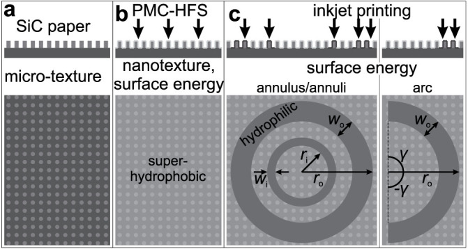
(a) The procedure begins with a micro-textured SiC substrate; (b) a PMC-HFS composite film is dropcast onto the SiC substrate forming a superhydrophobic surface (after drying); (c) hydrophilic inkjet patterns are successively applied until the desired level of hydrophilicity is achieved. ri and ro represent the inner and outer radii of the hydrophilic ring patterns, respectively. wi and wo represent the radial widths of the hydrophilic inner and outer rings, respectively. Arcs can be generated by eliminating the inner ring and setting the central angle (2γ) to be 2γ < 2π (in (c) 2γ = π).
Table 1. Concentrations of all ingredients used in the dispersion for generating superhydrophobic coatings by drop casting.
| Ingredients | Concentration (wt.%) |
|---|---|
| acetone | 87 |
| acetic acid | 6 |
| water | 4 |
| HFS | 2 |
| PMC | 1 |
In order to form a superhydrophobic surface, the PMC-HFS dispersion was drop-cast onto silicon-carbide micro-textured paper (1500 grit) and was allowed to dry for one hour in an oven at 80°C to remove any residual solvent. Such a dispersion, with its low surface tension, readily wets and wicks along the micro-textured features of the substrate forming a uniform film. The result is a coating with low-surface energy and a high-degree of hierarchical roughness. Subsequently, an inkjet printer (Kodak OfficeHero 6.1) was used to apply ink in the areas desired to be hydrophilic. One layer of the following colors was applied successively to the areas desired to be hydrophilic: magenta, yellow, cyan and gray (50% black). Areas that had multiple color layers printed on them ultimately appeared black; regions that printed incorrectly (spatially) would appear in their inherent color and thus expose a misprint. After each ink layer was applied, the ink was dried by gentle blowing with a hot air gun for 30 seconds. The result is a wettability-patterned coating on paper with precise domains of superhydrophobicity and hydrophilicity (see SI Section S1 for further details).
Wettability characterization on uniform-wettability areas was done by measuring apparent advancing ( ) and receding (
 ) water contact angle (CA) values by the stationary drop method, whereby 5–10 μL of the probe liquid was inflated (advancing CA
  ) and deflated (receding CA
  ) through a flat-tipped needle (32 gauge) placed over the surface. Images of the liquid volumes were captured with a high-speed, backlit image acquisition setup. A different location on the substrate was used for each individual CA measurement. Dynamic water droplet behavior (e.g., drop impact) on the substrates was captured with a modified version of the aforesaid image acquisition setup (see SI Section S2 for further details). The setup, all on a floating optical table, included a cool light source (Fostec 8375), high-speed camera (Redlake MotionPro or Vision Phantom M310), syringe pump (Cole Palmer 74900 Series), and needle (32 or 22 gauge, stainless steel, EFD). All optical and dispensing components were mounted on linear stages to allow for precise movement control. The distance L from the tip of the needle to the surface of the sample was varied in order to control the Weber number
  8, where ρ and σlv are the density and surface tension of water, respectively; Uy,0 and D0 are the velocity (normal to the surface, y-direction) and diameter of the impinging droplet, respectively. For droplet impact onto ring patterns, We was kept in the range 60–100; deionized water drops with diameter D0 = 2.1 mm were used for all experiments. For droplet impact onto arc wettability patterns, We was varied from 10 to 100 and the drop size was D0 = 2.9 mm, unless noted otherwise (see SI Section S3 for more details on wettability characterization).
Morphological characterization of micro-textured SiC in uncoated and coated states was performed with a scanning electron microscope (SEM; Hitachi S-3000 N). All samples were coated with a conformal 8 nm layer of Pt/Pd to facilitate SEM imaging.
Results and Discussion
For droplets impacting onto solid surfaces, two outcomes are possible: deposition or rebound (total or partial). For surfaces with isotropic wettability, the outcome can be predicted by the receding contact angle ( )9. Figure 2 illustrates this with a plot of contact line position (x) vs. time (t) for droplets impacting onto surfaces with isotropic wettability, i.e., superhydrophobic (
 ) or hydrophilic (
 ); the contact line in the former case advances and then recedes (recoil), while the contact line in the latter case gets pinned after the droplet reaches its maximum lateral spread (no recoil). For cases with anisotropic wettability, predicting the outcome is less clear (see SI Section S4). Figure 2 also shows the evolution of contact line position for a droplet impacting onto a hydrophilic arc on a superhydrophobic surface (see inset in (a) for a schematic; see (b) for image sequence as seen from the side). The contact line on the hydrophilic arc behaves as if it were in contact with an isotropic hydrophilic surface; on the superhydrophobic region, the contact line behaves as if it is in contact with a superhydrophobic surface, until x = 0. In the isotropic case, this is the point when rebound occurs (the droplet separates from the surface). In the anisotropic case, the contact line continues to recede until it reaches the hydrophilic arc, at which point rebound occurs; it is important to note that in this case the droplet is launched in a direction that is not orthogonal to the surface.
Figure 2.
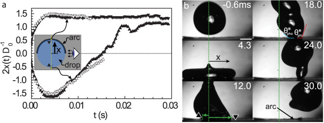
(a) Plot of contact line position (x) vs. time (t) for droplets impacting onto surfaces with isotropic (unfilled symbols) and anisotropic wettability (filled symbols). Anisotropic surfaces consisted of hydrophilic arcs on a superhydrophobic background (see inset image). Upward and downward facing triangles indicate the contact line was located on a superhydrophobic or hydrophilic region, respectively (We = 10, ro = 1.85 mm, wo = 0.2 mm, D0 = 2.9 mm). (b) Image sequence showing a water droplet impacting (We = 10) onto an anisotropic surface (hydrophilic arc on a superhydrophobic background; arc location indicated at 30.0 ms; refer to SI for a link to the full video, Video S1). The viewing angle is shown in the inset in (a). The positive x-direction (parallel to the surface) is indicated, as are the filled triangle symbols for the corresponding contact lines. Note how the contact lines on the left- and right-hand-side are free to move and pinned, respectively. At time 18.0 ms, the apparent contact angle values on the phobic ( ) and philic (
 ) regions are indicated. Note the large difference between them. Scale bar in (b) is 1.0 mm.
In the anisotropic case, since there is a significant difference in apparent contact angles from the hydrophilic to superhydrophobic regions (i.e., hysteresis), a net surface tension force develops during the receding phase of droplet impact —in the positive x-direction— potentially allowing lateral droplet rebound (vectoring) to occur. As shown in Figure 2, contact angle hysteresis occurs only after the droplet has reached its maximum spread (when the liquid gets pinned on the arc), i.e., only during the receding stage. The magnitude of this hysteresis force (Fσ) can be defined as a function of time according to
 |
where tr is the time after the droplet begins to recede (tr = 0),  and
and  the receding contact angles on the hydrophilic arc and superhydrophobic region, respectively, and τr the total receding time on the surface (see SI Section S5 for a detailed derivation). The above equation accounts for the fact that during the receding phase, the droplet is continuously de-wetting (peels off) the hydrophilic arc up to the instant of detachment (rebound). By integrating Equation 1 in time, one obtains the change in momentum (ΔP) due to the contact angle hysteresis force as
 |
where m is the mass of the droplet, and Ux the velocity of the droplet in the x direction (parallel to the surface). The subscripts 1 and 2 indicate when the receding phase begins and ends, respectively. We assume that: (i)  (receding contact angle does not vary on the superhydrophobic surface10; inertial regime of drop impact, i.e., We >> 1; K is a prefactor constant which depends on
  , see SI Section S5); and (ii) ro ≈ D0We0.25/2 (inviscid droplet11). The latter condition expresses the design requirement to have the arc coincide with the area under the droplet close to its outer periphery at the instant of maximum lateral spread. To satisfy (ii), the radius of the hydrophilic arc must be adjusted depending on the value of We employed. Under these conditions, Equations 1 and 2 can be combined and a horizontal restitution coefficient (εx) can be defined as
 |
where C is a prefactor defined as  . From Table 2, we see that
  (the subscripts r,phi and r,pho represent the receding contact angles on the philic and phobic regions); K = 3.1 as found experimentally (see SI Section S5); therefore, C ≈ 2.7. Equation 3 suggests that for drop impact events on hydrophilic arcs with diameter ≈ 2ro, εx has a We−0.25 dependence. This is supported by Figure 3a, which shows a plot of εx vs. We along with a best-curve fit for a function with C1We−0.25 (prefactor C1 = 0.8). Figure 3b shows a semi-log plot for the same variables along with a best-fit linear curve. The slope is −0.25, supporting the power-law behavior shown in Equation 3. The main point is that for orthogonal impact on a surface with asymmetric wettability, a predictable launch direction and velocity can be obtained, and the total outcome of the drop impact event can be predicted a priori. Figure 4 shows an image sequence demonstrating the droplet vectoring process. One drawback of the current system is that at higher values of We, smaller satellite droplets are formed during the impact process (Figure 4, 10.7 ms); under the same impact conditions on isotropic surfaces, no satellite droplets form.
Table 2. Water contact angle values on micro-textured silicon-carbide surfaces (sandpaper) for three cases: 1) Uncoated; 2) PMC-HFS composite coating; 3) Ink-coated PMC-HFS composite.
| Uncoated (°) | PMC-HFS (°) | Ink coated (°) | |
|---|---|---|---|
| θ* | 93 ± 17 | 159 ± 16 | 83 ± 23 |
 |
97 ± 3 | 166 ± 1 | 93 ± 5 |
 |
≈0 | 155 ± 6 | ≈0 |
Figure 3. Plots of the horizontal restitution coefficient (εx) as a function of We for droplets impacting on hydrophilic arcs on a superhydrophobic background: (a) linear and (b) semi-log scales.
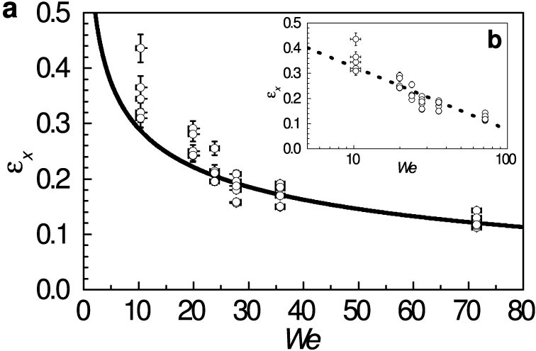
In (a), the fitted curve has the following form: εx = C1We−0.25 + C2 (C1 and C2 are fitting constants). In (b), the slope of the dashed line is −0.25.
Figure 4. Droplet impact onto a hydrophilic arc on a superhydrophobic background demonstrating vectoring behavior when We = 100.

The wettable arc can be seen (after being wetted) in the late stages of this event (after 9 ms). Note the formation of a small satellite droplet at 10.7 ms. The initial drop size was D0 = 2.1 mm and the arc had the following geometry, ro = 3.29 mm, wo = 0.20 mm (refer to SI for a link to the full video, Video S2).
It is also instructive to consider the relative horizontal velocity of the droplets in the context of other surface microfluidic systems. For a 1 μL water droplet impacting with We = 20, we see from Figure 3 that Ux,2 = 0.28 m s−1. If we compare Ux,2 with the meniscus velocities of other fast transport surface microfluidic systems (0.4 m s−1,12 0.3 m s−1,13 0.031 m s−1,14 0.005 m s−1,15), we see that the present velocities are either comparable or even higher than existing systems. In terms of miniaturization, the dimensionless groups that govern the scalability of the process are the Reynolds number (Re = D0Uy,0/ν; ratio of inertial and viscous forces; ν is kinematic viscosity of water) and We (ratio of inertial and surface tension forces). For this vectoring process to operate effectively, inertia should dominate. This is to ensure that droplet deformation occurs (We >> 1) and that viscous forces do not dissipate all of the energy (Re >> 1). For the cases presented in Figure 3, the ranges were We ≈ 10–70 and Re ≈ 1200–3300. If we consider a typical impact velocity from an inkjet printing process (Uy,0 = 3.0 m s−1) and we fix We = 10, then the minimum droplet size is D0 = 80 μm (typical D0 = 50–70 μm16). For the same impact velocity and D0 we calculate Re = 240. In this case, it appears that viscous forces will be the limiting factor in vectoring droplets.
The previous discussion emphasized controlling the outcome of droplets that strike surfaces with specially-designed wettability patterns; however, other designs of anisotropic surfaces may be useful for controlling the outcome of droplets that strike and stick to the surface, especially as this outcome relates to morphing the liquid volume. One of the major hurdles for droplet shaping on non-wetting surfaces is uncontrollable liquid ejection that can be caused by two primary mechanisms: 1) The final wetting state of the droplet on the wettability pattern is thermodynamically unfavorable (e.g., high free surface area of droplet); 2) the droplet does not remain pinned to the hydrophilic region during the vigorous drop impact process. The former problem can be dealt with by designing wettability patterns such that the final configuration of the droplet is stable, and is relatively trivial (see SI Section S6 for a detailed analysis of designing a stable annulus). The latter problem is more difficult to remedy, since the liquid regions near the contact line are very thin and are therefore the most susceptible to separation, provided that air bubbles exist below them4. Let us consider the case of a wettability pattern with two concentric hydrophilic circles; the final configuration of the liquid droplet after impact is an annulus (see Figure 5). In this case, ro and ri are predetermined from pre-impact parameters and the final equilibrium configuration of the liquid droplet; in other words, we modify wi and wo to ensure that the droplet remains pinned to the wettability pattern during the impact process. Both of these parameters were determined experimentally, and then validated theoretically; for a given value of We, wo and wi were incrementally increased until the pattern was capable of consistently stabilizing a liquid lens during vigorous droplet impact. In practice, wo was set to ≈500 μm, and wi was set to the minimum value achievable with the present patterning process (≈100 μm); any set width less than that did not produce a continuous line pattern. It should also be noted that liquid lens detachment generally did not occur from the inner ring, so a theoretical estimate of wi was not necessary. It has been previously shown that liquid lens detachment from wettability patterns can arise due to hole formation near the hydrophobic-to-hydrophilic terrain transition, as a result of air-bubble entrainment due to the fast moving contact line crossing from a Cassie-Baxter17 to a Wenzel18 wetting state4. By increasing wo, the spatial locations of the entrained air bubbles at the wettability transition are moved towards the center of the liquid lens; since the thickness of the liquid also increases closer to the center, it is hypothesized that hole formation in liquid lenses at the wettability transition area becomes less energetically favorable. In fact, for air-bubbles that are capable of forming penetrating holes of radius ~ 90 μm at the wettability transition when D0 = 2.1 mm and ro = 2.5 mm,4 once wo exceeds 150 μm, hole formation is no longer energetically favorable in the liquid lens. See detailed analysis in SI Section S7.
Figure 5. Droplet impact (We = 80) on concentric hydrophilic ring patterns with ro = 2.5 mm, wo = 0.5 mm, ri = 1.35 mm, and wi = 0.2 mm.
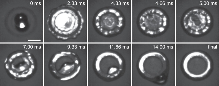
For the relatively high present values of We (≈80), it was observed that stable penetrating holes appeared very early in the impact process. If we consider t = 0 ms to be the moment of initial liquid/solid contact, then the first stable penetrating hole in the liquid lens appears at t ≈ 5 ms (cf. Figure 5). The process of hole formation at We ≈80 is difficult to interpret due to the highly dynamic character of the impact event. However, when the value of We was reduced to ≈60, and ro was reduced to 2.34 mm, a penetrating hole did not appear until much later, t ≈ 15 ms (see Figure 6), allowing a larger portion of the kinetic energy from the droplet impact to be dissipated and the penetrating hole formation process to be more visually clear. Such penetrating holes (air cavities) —which shape the liquid into a well-defined torus— have been observed before during droplet impact on superhydrophobic surfaces, are commonly referred to as “dry-out” events, and may lead to bubble entrainment19; viscous effects are small and the free surface state is controlled by the competition between surface tension and inertia forces19,20. It is known that during droplet impact on surfaces, it is possible for droplets to entrain macroscopic air bubbles near the impact zone during the early stages19,21,22,23,24, and thus it is possible to imagine future platforms to exploit this fact, i.e., capillary waves converging onto an entrained air bubble to produce a penetrating hole21. In any case, the fact that the penetrating hole is axisymmetric with respect to the liquid droplet, and forms later in the drop impact process, means that there is less of a tendency for liquid to be ejected, and is a preferable method for forming liquid annuli.
Figure 6. Droplet impact (We = 60) on a hydrophilic ring with ro = 2.34 mm and wo = 1.3 mm.
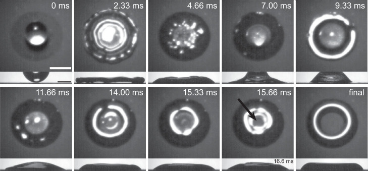
Both top and side views are given at each instant. Scale bar for top view is 2 mm; for side view 1 mm. The times for both views are synchronized, unless otherwise noted in the side view. The black arrow indicates when the first stable penetrating hole has formed.
Using the same technique resulting in the formation of the liquid ring (Figure 6), it is possible to create droplet patterns which are not radially symmetric. To demonstrate this, Figure 7 presents droplet impact with We = 100 on a cross wettability pattern. The hydrophilic square has an outer dimension of 4.5 mm and the centered inner hydrophobic cross has dimensions 2.7 mm × 0.87 mm. A penetrating hole forms in the liquid film —at the wettability transition— which grows to take up the shape of the hydrophobic cross, as previously shown for ring patterns. This impact sequence is very repeatable and consistent; even when the droplet impacted slightly off center, a hole still formed with no ejected satellites. One possible application of this process is rapid soft (water) templating for the purposes of forming films of complex geometries. To demonstrate this technique, a low-temperature sintering silver nanoparticle ink was added to the water cross pattern formed in Figure 7. The process is shown in Figure 8, where the silver nanoparticle ink was added on the water template by a pipette; see Figure 8c. The sample was placed in a dry air convection oven at 120°C for 180 s to convert the ink to silver; the manufacturer states that if conditions are optimized, then this type of silver can sinter in seconds. Taking a close look at one of the corners of the silver pattern (Figure 8e), it can be seen that the silver was restrained onto the hydrophilic domain and did not extend onto the hydrophobic surface.
Figure 7. Droplet impact with We = 100 on a wettable square domain with sides of 4.5 mm and an included hydrophobic cross (Swiss flag) pattern (band length 2.7 mm, width 0.87 mm).
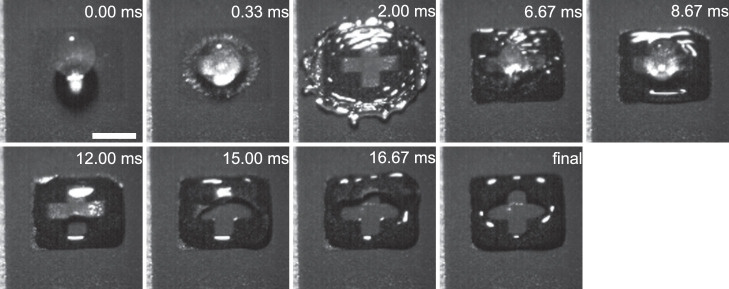
Scale bar denotes 2 mm.
Figure 8. Soft templating process example using the present approach.
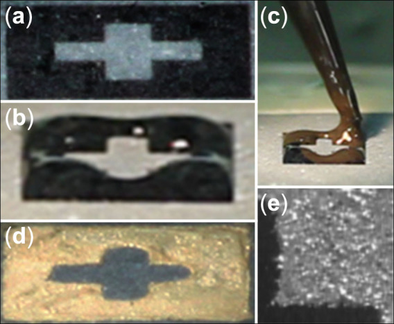
(a) Cross pattern identical to that shown in Figure 7; (b) water drop impact with We = 100 leaves a water template of the desired pattern; (c) silver nanoparticle ink is dispensed onto the water template; (d) silver film after sintering; (e) closeup detail of (d) shows the silver film accommodating the sharp angles on the hydrophilic patterned section and not extending onto the hydrophobic area shown in black.
While the above discussion emphasized complex shaping —in a well controlled and highly repeatable manner—of liquid volumes striking wettability-patterned surfaces, the fact that advancing contact line behavior is inertia-dominated and receding contact line motion is wettability-dominated can be used to also split liquid micro-volumes. Figure 9 shows a sequence of snapshots of a water droplet impacting with We = 60 centrally on a superhydrophobic line of width 0.5 mm. The surface on both sides of the superhydrophobic line is hydrophilic. As seen previously, the drop reaches its maximum spreading radius at t = 2.33 ms. The shape of the contact line is slightly irregular due to the differences in wettability of the surface, which affect symmetry. From the maximum spreading radius, the contact line on the hydrophobic strip recedes quickly, while the rest of the contact line is pinned on the hydrophilic parts of the surface, thus receding only slightly during the same period. As a result, a liquid bridge between two main separating parts of the drop forms; finally, the bridge collapses, leading to separation of the drop —in under 18 ms from initial contact— into two drops of equal size. Clearly, this wettability pattern acts as a liquid “scalpel”25. Experiments at lower values of We (<30) show that splitting is not possible with this same surface (see SI Section S8), suggesting the critical role inertia plays in the splitting process. Additional experiments revealed that as the superhydrophobic line became wider, the droplet required a higher maximum lateral spread (i.e., likewise We) in order to reach the hydrophilic regions, leading to an increased risk of partial rebound and “sling shot” action, resulting in partial loss of the liquid volume (see SI Section S8). This loss is not desirable in surface microfluidic devices. While the above effort was focused on splitting a droplet in two, such wettability engineered surfaces are capable of a much higher rate of droplet sampling. Proper wettability patterns were also shown to be able to rapidly sample a large number (24 droplets) of small volumes in ~0.01 s (see SI Section S8).
Figure 9. Droplet impact with We = 60 on a superhydrophobic strip (here oriented top-to-bottom) with width of 0.5 mm.
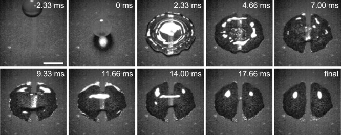
The surface is oriented horizontally. The impact results in droplet splitting into two identical volumes with no errant loss of fluid. Scale bar is 2 mm. Refer to SI for a link to the full video, Video S4.
Conclusion
This study presented an investigation into morphing and vectoring liquid micro-volumes through energetic droplet impact on wettability-engineered surfaces, with an emphasis on controlling post-impact behavior —a promising approach to tuning impact outcome (e.g., deposition or bounce). Both procedures rely on the competition between surface tension and fluid inertial forces, and have important ramifications for surface microfluidics and soft templating applications. The work demonstrated highly repeatable events wherein droplets were converted into tori without loss of liquid, as well as splitting and high-rate sampling. The results indicate that it is possible to morph and fractionalize droplet volumes using simple patterning procedures and commercially available materials. Droplet vectoring using wettability-patterned surfaces was also studied, with results demonstrating the capability to manipulate vectoring behavior by controlling We and asymmetric pattern construction. Notably, achieved lateral velocities were comparable to, if not greater than those previously reported in the literature for surface microfluidic devices. Particular emphasis was placed on the efficiency and limits of the procedure for designing practical wettability patterns.
Author Contributions
C.M.M. and T.M.S. conceived the project and planned the experiments. T.M.S., G.G., J.O. and M.E. fabricated samples, carried out experiments and analyzed data. T.M.S. and M.E. developed the theoretical analysis. All authors contributed to writing and approved the manuscript.
Supplementary Material
Supporting Information
Video S1
Video S2
Video S3
Video S4
Acknowledgments
GG was supported by a DAAD-RISE Internship Award during the summer of 2012. TMS acknowledges Prof. Ranjan Ganguly (Jadavpur University) for useful discussions. We thank PChem Associates, Inc. for providing the silver ink. M.E. was supported by a National Science Foundation Graduate Research Fellowship under Grant No. 0907994.
References
- Deng T. et al. Nonwetting of impinging droplets on textured surfaces. Appl. Phys. Lett. 94, 133109 (2009). [Google Scholar]
- Maitra T. et al. On the nanoengineering of superhydrophobic and impalement resistant surface textures below the freezing temperature. Nano Lett. 14, 172–182 (2013). [DOI] [PubMed] [Google Scholar]
- Bird J. C., Dhiman R., Kwon H.-M. & Varanasi K. K. Reducing the contact time of a bouncing drop. Nature 503, 385–388 (2013). [DOI] [PubMed] [Google Scholar]
- Kim S., Moon M.-W. & Kim H.-Y. Drop impact on super-wettability-contrast annular patterns. J. Fluid Mech. 730, 328–342 (2013). [Google Scholar]
- Malouin B. A., Koratkar N. A., Hirsa A. H. & Wang Z. Directed rebounding of droplets by microscale surface roughness gradients. Appl. Phys. Lett. 96, 234103 (2010). [Google Scholar]
- Jokinen V., Sainiemi L. & Franssila S. Complex droplets on chemically modified silicon nanograss. Adv. Mater. 20, 3453–3456 (2008). [Google Scholar]
- Lee M., Chang Y. S. & Kim H.-Y. Drop impact on microwetting patterned surfaces. Phys. Fluids 22, 072101 (2010). [Google Scholar]
- Thoraval M.-J., Takehara K., Etoh T. G. & Thoroddsen S. T. Drop impact entrapment of bubble rings. J. Fluid Mech. 724, 234–258 (2013). [Google Scholar]
- Antonini C., Villa F., Bernagozzi I., Amirfazli A. & Marengo M. Drop rebound after impact: The role of the receding contact angle. Langmuir 29, 16045–16050 (2013). [DOI] [PubMed] [Google Scholar]
- Bartolo D., Josserand C. & Bonn D. Retraction dynamics of aqueous drops upon impact on non-wetting surfaces. J. Fluid Mech. 545, 329 (2005). [Google Scholar]
- Clanet C., Beguin C., Richard D. & Quéré D. Maximal deformation of an impacting drop. J. Fluid Mech. 517, 199–208 (2004). [Google Scholar]
- Khoo H. S. & Tseng F.-G. Spontaneous high-speed transport of subnanoliter water droplet on gradient nanotextured surfaces. Appl. Phys. Lett. 95, 063108 (2009). [Google Scholar]
- Elsharkawy M., Schutzius T. M. & Megaridis C. M. Inkjet patterned superhydrophobic paper for open-air surface microfluidic devices. Lab Chip 14, 1168–1175 (2014). [DOI] [PubMed] [Google Scholar]
- Schutzius T. M., Elsharkawy M., Tiwari M. K. & Megaridis C. M. Surface tension confined (STC) tracks for capillary-driven transport of low surface tension liquids. Lab Chip 12, 5237–5242 (2012). [DOI] [PubMed] [Google Scholar]
- Zahner D., Abagat J., Svec F., Frechet J. M. J. & Levkin P. A. A facile approach to superhydrophilic-superhydrophobic patterns in porous polymer films. Adv. Mater. 23, 3030–3034 (2011). [DOI] [PubMed] [Google Scholar]
- Szczech J., Megaridis C. M., Gamota D. & Zhang J. Fine-line conductor manufacturing using drop-on demand PZT printing technology. IEEE Trans. Electron. Packag. Manuf. 25, 26–33 (2002). [Google Scholar]
- Cassie A. & Baxter S. Wettability of porous surfaces. T. Faraday Soc. 40, 546–551 (1944). [Google Scholar]
- Wenzel R. N. Resistance of solid surfaces to wetting by water. Ind. Eng. Chem. 28, 988–994 (1936). [Google Scholar]
- Bartolo D., Josserand C. & Bonn D. Singular jets and bubbles in drop impact. Phys. Rev. Lett. 96, 124501 (2006). [DOI] [PubMed] [Google Scholar]
- Renardy Y. et al. Pyramidal and toroidal water drops after impact on a solid surface. J. Fluid Mech. 484, 69–83 (2003). [Google Scholar]
- Thoroddsen S. T., Takehara K. & Etoh T. G. Dewetting at the center of a drop impact. Mod. Phys. Lett. B 23, 361–364 (2009). [Google Scholar]
- Lee J. S., Weon B. M., Je J. H. & Fezzaa K. How does an air film evolve into a bubble during drop impact? Phys. Rev. Lett. 109, 204501 (2012). [DOI] [PubMed] [Google Scholar]
- Bouwhuis W. et al. Maximal air bubble entrainment at liquid-drop impact. Phys. Rev. Lett. 109, 264501 (2012). [DOI] [PubMed] [Google Scholar]
- Antonini C. et al. Unraveling wetting transition through surface textures with x-rays: Liquid meniscus penetration phenomena. Sci. Rep. 4, 4055 (2014). [DOI] [PMC free article] [PubMed] [Google Scholar]
- Bormashenko E. & Bormashenko Y. Non-stick droplet surgery with a superhydrophobic scalpel. Langmuir 27, 3266–3270 (2011). [DOI] [PubMed] [Google Scholar]
Associated Data
This section collects any data citations, data availability statements, or supplementary materials included in this article.
Supplementary Materials
Supporting Information
Video S1
Video S2
Video S3
Video S4


