Abstract
A popular alternative of preparing multilayer or microfluidic chip based phantoms could have helped to simulate the subsurface vascular network, but brought inevitable problems. In this work, we describe the preparation method of a single layer skin equivalent tissue phantom containing interior vessel channels, which mimick the superficial microvascular structure. The fabrication method does not disturb the optical properties of the turbiding matrix material. The diameter of the channels reaches a value of 50 μm. The size, as well as the geometry of the generated vessel structures are investigated by using the SD-OCT system. Our preliminary results confirm that fabrication of such a phantom is achievable and reproducible. Prospectively, this phantom is used to calibrate the optical angiographic imaging approaches.
OCIS codes: (170.0170) Medical optics and biotechnology, (110.7050) Turbid media, (170.3880) Medical and biological imaging, (160.4760) Optical properties, (350.0350) Other areas of optics
1. Introduction
Optical imaging studies are widely performed in clinical or experimental trials to reconstruct human organs, such as brain, liver, breast and skin. Inversely, these organs are most commonly mimicked to calibrate the optical imaging approaches and to determine the adaptivity of such devices on biological objects [1, 2]. For this purpose, these mimicked body parts should be modeled with equivalent tissue phantoms. Phantoms for optical studies have already fulfilled the requirements of stability, biological compatibility, and replicated the representative values of specific optical properties of the real tissue [1–6]. These requirements have now swayed into generating realistic physiological structures, that permits an increasing complexity of optical imaging studies on tissue phantoms [7–9].
Mapping the microvascular network under skin promotes the understanding of some specific types of vascular dermatosis or the local angiogenic activities during the tumor progression in skin. To verify the feasibility of applying optical imaging approaches on recovering the superficial microvasculature, skin phantoms with subsurface structures should be particularly prepared for this scenario. In view of skin equivalent phantoms, many researches have been conducted onto the concept of multilayers that imitate the layers of the cutis: epidermis, dermis. Multilayer structure favors to assess some imaging modalities and their associated algorithms [9–12]. It is even practical to emboss vessel structures in multilayer phantoms to include biological / artificial solution [8, 13]. As a typical example, a blood perfused finger phantom was prepared by folding glass tubes between layers to create an array of vessel structures [14]. J. T. Wang et al. presented an additive production process to print a vessel pattern inside a phantom in their pioneer work [15]. These embossed structures lack of an exact dimensional analogy to the real microvascular according to the morphology of skin [13–15]. Fast prototyping of pattern on microfluidic chip is becoming a popular option to simulate the nature of superficial microvasculature and achieve a dimensional similarity [16].
However, experiments on multi-layer phantom [14], 3-D printed phantom [15] or microfluidic chip [16], are not easily duplicated in a few steps or without particular equipments. It means, they have an innate shortcoming of cumbersome to mass manufacture. Traditional fabrication of microfluidic chips using soft lithography, hot embossing could be even more complicated and costly [17].
It is crucial to decrease the diameter of the embedded vessel structures to a value resembling a real microvasculature. Another challenge is, that the optical properties of this phantom replicate those of skin tissue and should not be significantly changed by the fabrication process. This work pertains to prepare a skin equivalent phantom with micron-scale interior hollow vessel channels to utilize biological / artificial inclusion. Ultimately, this phantom will be used to calibrate the optical angiographic approaches, like SD-OCT, diffuse optical imaging or hyper-spectral imaging studied in our lab.
2. Material and methodology
2.1. Designing and preparing the casting mold
The diameter of a real microvascular structure under skin ranges from 10 to 100 μm, the capillary network is mostly bedded in the first 200 μm of the skin subsurface. To simulate this, we intend to derive thin hollow vessel channels with a diameter of 50 μm at the depth of 150 to 200 μm from the surface. The entire progress is summarized as embedding-and-etching copper wires in the matrix material of the phantom.
An iron cylinder is firstly prepared as the casting mold to regulate the positioning of the vessel channels in phantom. We use a ps-laser (TBWP Fuego ps-laser, Time-Bandwidth Products AG, Switzerland) to drill holes through the wall of this mold. A laser beam spot is located on the defined positions by rotating the mold with a chuck. The focused laser beam scans over the wall in a circular hatched pattern to ablate the metal. By this method, a minimal drilling threshold of 50 μm in diameter as well as a sharp edge around the holes is produced. Conventional drilling machine, like an electrical discharging drilling machine, could also be used in this case. No specific means of machining are necessary.
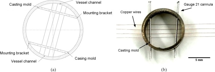
Holes with a diameter of 100 μm are stamped through the wall to fix the copper wires (ϕ = 50 μm, Conrad Electronic GmbH, Germany). Likewise, holes with a diameter of 400 μm are drilled to fix the 21 gauge cannulas as the mounting brackets of the copper wires. Altogether 8 holes (each 4 for every 10 degrees symmetrically on the opposite of the cylinder mold) for inserting copper wires and 4 holes (respectively at 60°, 140°, 240°, 320°) for inserting canullas are proposed. In this design as shown in Fig. 1(a), 2 mounting brackets perpendicularly cross over 4 copper wires. Copper wires and cannulas are plugged into the corresponding drilling holes afterwards (see Fig. 1(b)). Hollow vessel channels should be left in the phantom after the copper wires and canullas are eliminated from the matrix material.
Fig. 1.
(a) Schematic of the cylinder casting mold design for regulating 4 rows of vessel channels in the tissue phantom and (b) image of a finished casting mold with 4 rows of copper wires and 21 gauge cannulas inserted through the drilling holes
2.2. Preparing the matrix material
For simulated studies on skin via optical imaging approaches, especially with diffuse optical imaging (DOI), the phantom should allow for similar absorption coefficient μa and reduced scattering coefficient μs′ to a real skin tissue in the wavelength dependence. Therefore, we choose the data from ex-vivo caucasian skin tissues [18, 19] as the reference. The tissue phantom is constructed with castable aliphatic polyurethanes (WC-781, BJB Entprise Co., US). To replicate the optical properties of the caucasian skin, 0.7 g of titanium oxide powder (Sigma-Aldrich GmbH, Germany) and 3.3 μL of india ink (Pelikan GmbH, Germany) [4,18,20,21] are added into 100 mL of polyurethane component. The additives are dispersed by 20 min stirring, followed with an ultrasound bath (Elmasonic P, Elma Hans Schmidbauer GmbH, Germany) under 60 °C. We also use a vacuum autoclave to extract the air bubbles from the viscous mixture before casting. Casting is excuted at 30 °C in a convection chamber (BINDER GmbH, Germany), where a dehydrated ambience helps to reduce the reactive air bubbles in polyurethane. Solidified phantom is de-molded after 48 h, when most mechanical properties (e.g. shore hardness = 82 D) are reached.
2.3. Etching the retained copper wires
Ferric chloride is used to eliminate the folded copper wires from the fabricated phantom. To avoid the swelling of polyurethane, the concentration of FeCl3 (Sigma-Aldrich Co., US) is restricted at 50 g/L, without adding acid adjuvant. We precipitate the de-molded phantom into the ferric chloride solution, keep the ambient temperature at 45 °C and stir the solution every 1 hour to avoid the material stagnation on the local corrosion knot. Ferric chloride solution perfuses into the channels and dissolves the wires without disrupting the wall of the channels, thus produces a finished phantom.
However, the etching progress might alterate the optical properties of the phantom. Possible attenuation mainly stems from the dying of titanium oxide particles on the surface during their contact with the ferric chloride solution. Due to this, we use UV-IR spectrophotometry (UV-3600 seires, SHIMADZU Co., Japan) to characterize the optical properties through the matrix material of the phantom before and after etching, as well as to verify the chemical resistance of polyurethane to ferric chloride. To do this, spectra of absorbance Ab, diffuse reflectance Rd, diffuse transmittance Td and total transmittance Tt are measured. We also investigate the geometry of the vessel structures and evaluate the uniformity of the diameter along the vessel channels by using a SD-OCT (Telesto-II-SP1, Thorlabs GmbH, Germany).
3. Results and discussion
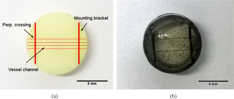
We prepare a phantom as the object sample containing 4 separate rows of vessel channels with replicated optical properties (see Fig. 2(a)). Besides, a simplified reference phantom with 2 rows of vessel channels is constructed without inserting scatters and absorbers. This transparent phantom is individually prepared to monitor the dissolving of the copper wires in the matrix material and to prove the perfusability of the vessel channels by including with ink (see Fig. 2(b)) Although air bubbles remain in the transparent phantom, they do not affect its function even when the de-gasing is skipped for time efficiency.
Fig. 2.
Picture of (a) a finished tissue phantom with 4 rows of vessel channels perpendicularly crossing over 2 mounting brackets and (b) a finished transparent tissue phantom with 2 rows of channels, they are included with india ink to highlight the hollow vessel channels against the matrix material
3.1. Characterizing the attenuation in optical properties
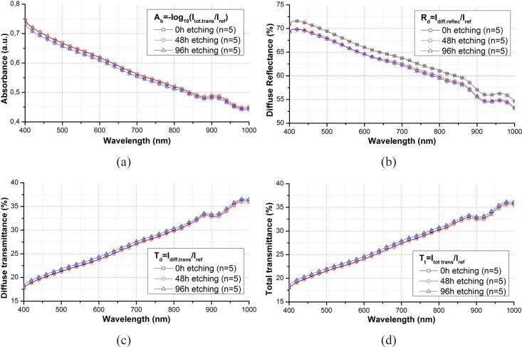
Figure 3 show the spectra before, after 48 h and after 96 h etching averaged out of the spectra from 5 random points of a phantom slab.
Fig. 3.
Comparison of (a) absorbance, (b) diffuse reflectance (c) diffuse transmittance and (d) total transmittance spectra through a phantom slab before and after etching in wavelength range from 400 to 1000 nm and their standard derivation.
Spectra of Ab, Td and Tt do not change with the etching progress. The registered spectra from before and after etching show the same trace with an overlaying error bar in the full wavelength range. The standard deviations of these spectra do not exceed ± 1 %. Values of Rd alterate a bit after etching, with a drop of around 4 %. This drop is mostly caused by the induced change of the surface status, as the surface layer of the phantom slab is dyed during etching.
To verify the reproduciblity of these results, same experiments are respectively repeated on 4 phantom slabs with different content of titanium oxide. Table 1 summerizes the attenuation rate of the Tt, Td, Ab and Rd before and after etching, with regarding to the weight of titanium oxide in 100 mL of polyurethane. According to Tbl. 1, a higher content of TiO2 could have increased the change of optical properties, espcially diffuse reflectance. Nevertheless, This change does not exceed 5 %, which is rather slight and therefore acceptable. By comparing these spectra, it can be verified that the ferric chloride solution does not reveal any significant alteration in the optical properties of the turbid phantom slab.
Table 1.
Attenuation in the values of Tt, Td, Ab and Rd with regarding to different content of titanium oxide in 100 mL of polyurethane
| CtTiO2 (g / 100 mL) | Att Tt (%) | Att Td (%) | Att Ab (%) | Att Rd (%) |
|---|---|---|---|---|
| 0.5 | 0.3 | 0.1 | 0.8 | 3.3 |
| 0.7 | 0.4 | 0.2 | 1.0 | 3.9 |
| 1 | 0.8 | 0.4 | 1.2 | 4.1 |
| 2 | 1.1 | 0.5 | 1.6 | 4.9 |
3.2. Optical properties compared with ex-vivo skin tissue
The reference optical properties are reported elsewhere in [18, 19], the paradigm of absorption coefficient μa and reduced scattering coefficient μs′ are attained from the whole skin slabs out of 21 caucasian human objects at wavelengths of 500, 600 and 700 nm and converted using a single intergration sphere and inverse adding doubling [21]. Likewise, we measure the same coefficients from the tissue phantom at the same wavelengths (see Tbl. 2). The absorption coefficient μa is close to that of the real ex-vivo skin tissue. μs′ is slightly overestimated. This could be further modified by reducing the amount of the titanium oxide particles. The refractive index of phantom is lower than the real value at 500 nm [22]. Nevertheless, this is not disturbing, when μa and μs′ approach the values of the ex-vivo tissue [23].
Table 2.
Optical properties of the ex-vivo caucasian skin tissues and tissue phantom calculated by inverse adding doubling with a single integrating sphere
| object | λ (nm) | μa(cm−1) | μs′ (cm−1) | refractive index |
|---|---|---|---|---|
| – | – | Ave ± E.R. | Ave ± E.R. | – |
| Tissue phantom | 500 | 0.12 ± 0.01 | 5.71 ± 0.13 | 1.31 |
| 600 | 0.112 ± 0.01 | 3.78 ± 0.09 | ||
| 700 | 0.097 ± 0.01 | 2.8 ± 0.07 | ||
|
| ||||
| Caucasian skin | 500 | 0.16 | 4.2 | 1.41–1.62 |
| 600 | 0.13 | 3.0 | ||
| 700 | 0.11 | 2.3 | ||
Summarizing from the previous results, we have successfully fabricated the object phantom with 4 seperate rows of vessels and a transparent phantom to ensure the feasibility of including liquid into the hollow vessels. The object sample replicates the optical properties of a caucasian skin. Comparing the registered spectra from before and after etching, it is confirmed that the chemical resistance of polyurethane to ferric chloride at 45 °C is a strong hold, the etching progress does not lead to any significant attenuation in the optical properties of the phantom. Such a slight attenuation on the surface of the phantom slab can even be neglected, as if the dyed section is ground off beforehand. Limit stays, that the reducing the attenation on the wall of the generated vessel channels is beyond our ability, although such a slight drop of the diffuse reflectance at 4 – 5 % is acceptable.
In contrast, direct engraving on the matrix material via thermal, mechanical or photonic fabrication brings inevitable problems. For instance in the fast prototyping method [16], discussion about the changes of optical properties in the heat affected zone (HAZ), induced by laser micro-machining, is missing. Moreover, it is critical to package the microfluidic chip with an adhesive material, whose optical properties attenuate over time. Other engraving methods could mostly disturb the optical properties of the turbiding matrix material [17]. Although the nature of the mutilayers of skin cutis can not be simulated, like described in [2, 10, 14], the diameter of the generated vessels, that we pursued, is more close to that of a real vascular compared to the results from Refs. [12–15]. Further discussion goes onto investigating the geometry of the generated vessel structures.
3.3. Investigating the geometry of vessel channels
The diameter and depth of the vessel channels are separately measured on the finished tissue phantom over around the mounting bracket using the optical microscopy (OM) and optical coherence tomography (OCT).
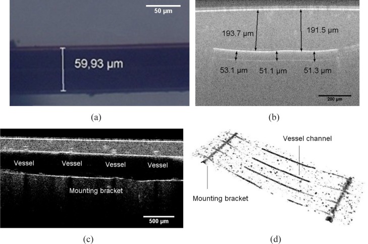
The OM graphic (see Fig. 4(a)) demonstrates a single vessel channel in the transparent tissue phantom. Regarding a volume shrinkage ratio of the aliphatic polyurethane, the approximately achievable diameter of the vessel channels should be around 55 μm. The measured value is 59 μm on average, which shows an excellent agreement to the estimated value.
Fig. 4.
(a) OM graphic of a generated vessel channel dyed with india ink in a transparent tissue phantom (b) OCT B-scan image of the cross section passing along a vessel channel (c) OCT B-scan image of the cross section passing along a mounting bracket across the the vessel channels (d) OCT volume view of the segmentated vessel structures, including vessel channels and mounting brackets
In order to validate the vessel geometry more directly, we refer to OCT for a reconstruction of the vessel structures entirely, or partially around a certain area of interest. Using OCT, we can recover the cross section passing along a vessel channel (see Fig. 4(b)), along the mounting bracket across the vessel channels (see Fig. 4(c)) through a B-scan, and a segmented vessel structures in a 3-D volume view (see Fig. 4(d)). Similarly, the measured value of vessel diameter is about 52 μm on average. The vessels are uniform in diameter along the entire structure, with a tolerance of ± 3.3 μm. Conclusion could be drawn, that the geometric parameters of the vessel channels conform the original intension of design.
The diameter of the generated vessels is decided by the master mold of the inserted copper wires. However, the core diameter of the wire with a value smaller than 50 μm is not off-the-shelf. Further decrease of vessel dimension could be implemented by using an ultra-thin-wire. In this case, we attempt to produce a thinner wire by eroding the ϕ 50 μm copper wires to ϕ 20 μm with electrolysis. Experiments are repeated with a low erosion rate to get a core diameter close to the aimed value. Geometry of the generated vessel are observed after the eroded wires are dissolved from a transparent phantom. The results are summarized in Tbl. 3.
Table 3.
Estimated and real values of diameter of the eroded copper wires and generated vessel channels in a transparent phantom slab
| Aimed value (μm) | 50 | 40 | 30 | 20 |
|---|---|---|---|---|
| Ave. diameter of wires (μm) | 51 | 37 | 31 | 22 |
| Ave. diameter of vessels (μm) | 59 | 42 | 36 | 24 |
We demonstrate that the embedding-and-etching method can create a hollow vessel with a diameter down to ϕ = 20 μm. Although we doubt the dimensional uniformity of such a vessel channel, the value of the diameter still reaches the unique feature value, recorded elsewhere in [16]. Uniformity could be simply improved by using ultra-thin-wires.
3.4. Deformation of the vessel channels
It is apparently indicated in the OCT B-scan image (see Fig. 5(a)), that the vessel channels may deviate from the supposed normal latitude. In this subfigure, the distance from the upper outline of the generated vessel channels to the surface ranges from ϕ 120 μm to ϕ 210 μm.
Fig. 5.

(a) OCT image of the cross section across over 4 vessel channel, showing that they are not located on the same latitude of around 160 μm to the surface (b) OCT top view of vessel channels in tissue phantom : vessel channels bend in tangential direction along the structure due to the inner stress induced during solidification
This occurs because of the thermometrical force inside the polyurethane in tangential direction, induced by rapid cooling during solidification. It is even more visibly obvious from the OCT top view (see Fig. 5(b)), that the channels bend along the structure. Such a deviation could even reach dozens of micrometers. This phenomena, although random and even inevitable, could be reduced by cooling the polyurethane in a cooling rate at aroud 1 °C / min until 30 °C.
3.5. Improving homogeneity of scatter
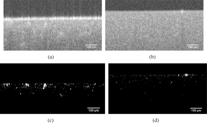
The homogeneity of scatters influences the light propagation in turbid media. The agglomeration of the titanium oxide particles may exist until the matrix material is solidified, thus forms a scattering cluster. In our case, the diameter of the generated vessel channels encloses to the feret diameter of the scattering clusters. Scattering clusters might be misidentified, or fracture the real target of interest, namely the vessels. Such scattering clusters must be, and could be reduced by a longer ultra-sound bath, which smashs and disperses the powder agglomeration. To do this, a 2 h ultra-sound-bath is executed to substitute the 20 min stirring.
To check the consequence of this homogenization, scatter homogeneity is evaluated from the OCT B-scan image by using an image post-processing software (ImageJ, National Institutes of Health, US) respectively before and after homogenization. The scattering clusters are thresholded, and morphologically opened during the post processing of the OCT images (see Fig. 6 from (a) to (c), or from (b) to (d)). Those scattering clusters, whose size exceed a certain value, are contrasted against the background. By comparing Fig. 6(d) to (c), we find that the speckeling spots are mostly vanishing from Fig. 6(d). The claim is, that the amount and the size of scattering clusters decrease after homogenization. Further problems like the residual air bubbles could be solved by inserting anti-foam components. In this way, quality of the tissue phantom could be ensured.
Fig. 6.
Origin OCT B-Scan image of the cross section of (a) a typically inhomogeneous tissue phantom (b) homogenous tissue phantom, subfigures (c) and (d) demonstrate the segmentated scattering clusters corresponding to (a) and (b)
4. Conclusion
In the framework of preparing a skin equivalent tissue phantom containing thin interior vessel channels, prototype with 4 separate rows of channels are constructed. Optical properties similar to real ex-vivo caucasian skin tissues are replicated and not attenuated by the embedding-and-etching progress. With the OCT studies, we assure the feasibility of creating a vessel structure with a diameter of 52 μm at a depth of 150 to 200 μm from the phantom surface. Our fabrication method is easily reproduced, and does not require any specific equipments. Future work will be conducted onto upgrading the geometric complexity of the vascular pattern and varying the optical properties for a phantom databank. The fabrication of this phantom also provides a fresh frame of mind to prepare a multi-layer tissue phantom, with an overlaying microvascular network, and meanwhile, without using any adhesive sealing material. Our upcoming work will be to recover this superficial microvascular pattern with a customized diffuse optical imaging apporach.
Acknowledgments
The authors gratefully acknowledge the funding of the Erlangen Graduate School in Advanced Optical Technologies (SAOT) by the Deutsche Forschungsgemeinschaft (German Research Foundation - DFG) within the framework of the Initiative for Excellence, and the Institute of Photonic Technologies of Friedrich-Alexander-Universität Erlangen-Nürnberg. Authors would like to express special thanks to Mr. Jörn Wollenzin and Mr. Dr.-Ing Micheal Leitner from the department of imaging systems of THORLABS, for the instruction on OCT imaging.
References and links
- 1.Firbank M., Delpy D. T., “A design for a stable and reproducible phantom for use in near infra-red imaging and spectroscopy,” Phys. Med. Biol. 38(6), 847 (1993) 10.1088/0031-9155/38/6/015 [DOI] [PubMed] [Google Scholar]
- 2.Pogue B. W., Patterson M. S., “Review of tissue simulating phantoms for optical spectroscopy, imaging and dosimetry,” J. Biomed. Opt. 11(4), 041102 (2006) 10.1117/1.2335429 [DOI] [PubMed] [Google Scholar]
- 3.Lualdi M., Colombo A., Farina B., Tomatis S., Marchesini R., “A phantom with tissue-like optical properties in the visible and near infrared for use in photomedicine,” Laser. Surg. Med. 39(3), 237–243 (2001) 10.1002/lsm.1044 [DOI] [PubMed] [Google Scholar]
- 4.Roystonand D. D., Poston R. S., Prahl S. A., “Optical properties of scattering and absorbing materials used in the development of optical phantoms at 1064 nm,” J. Biomed. Opt. 1(1), 110–116 (1996) 10.1117/12.227698 [DOI] [PubMed] [Google Scholar]
- 5.Lamouche G., Kennedy B. F., Kennedy K. M., Bisaillon C. E., Curatolo A., Campbell G., Pazos V., Sampson D. D., “Review of tissue simulating phantoms with controllable optical, mechanical and structural properties for use in optical coherence tomography,” Biomed. Opt. Express 3(6), 1381–1398 (2012) 10.1364/BOE.3.001381 [DOI] [PMC free article] [PubMed] [Google Scholar]
- 6.Cooper R. J., Eames R., Brunker J., Enfield L. C., Gibson A. P., Hebden J. C., “A tissue equivalent phantom for simultaneous near-infrared optical tomography and EEG,” Biomed. Opt. Express 1(2), 425–430 (2010) 10.1364/BOE.1.000425 [DOI] [PMC free article] [PubMed] [Google Scholar]
- 7.Mudaliar A. V., Development of a Phantom Tissue for Blood Perfusion Measurement and Noninvasive Blood Perfusion Estimation in Living Tissue (Virginia Polytechnic Institute and State University, 2007) [Google Scholar]
- 8.De Korte C. L., Cespedes E. I., Van der Steen A. F. W., Norder B., te Nijenhuis K., “Elastic and acoustic properties of vessel mimicking material for elasticity imaging,” Ultrasonic imaging 19(2), 112–126 (1997) 10.1177/016173469701900202 [DOI] [PubMed] [Google Scholar]
- 9.Dabrowski W., Dunmore-Buyze J., Rankin R. N., Holdsworth D. W., Fenster A., “A real vessel phantom for imaging experimentation,” Med. Phys. 24, 687 (1997) 10.1118/1.597991 [DOI] [PubMed] [Google Scholar]
- 10.Surowiec A., Shrivastava P. N., Astrahan M., Petrovich Z., “Utilization of a multilayer polyacrylamide phantom for evaluation of hyperthermia applicators,” Int. J. Hyperther. 8(6), 795–807 (1992) 10.3109/02656739209005027 [DOI] [PubMed] [Google Scholar]
- 11.Saager R. B., Kondru C., Kendrew A. U., Sry K., Ayers F., Durkin A. J., “Multilayer silicone phantoms for the evaluation of quantitative optical techniques in skin imaging,” Proc. SPIE 7567, 756706 (2010) 10.1117/12.842249 [DOI] [Google Scholar]
- 12.Bykovand A. V., Popov A. P., Priezzhev A. V., Myllylä R., “Multilayer tissue phantoms with embedded capillary system for OCT and DOCT imaging,” Proc. SPIE 8091, 80911R (2012) [Google Scholar]
- 13.Bykov A. V., Popov A. P., Kinnunen M., Prykäri T., Priezzhev A. V., Myllylä R., “Skin phantoms with realistic vessel structure for OCT measurements,” Proc. SPIE 7376, 73760F (2010) 10.1117/12.872000 [DOI] [Google Scholar]
- 14.Tuchin V. V., Bashkatov A. N., Genina E. A., Kochubey V. I., Lychagov V. V., Portnov S. A., Trunina N. A., Miller D. R., Cho S., Shim B., Kim M., Oh J., Eum H., Ku Y., Kim D., Yang Y., “Finger tissue model and blood perfused skin tissue phantom,” Proc. SPIE 7898, 78980Z (2011) 10.1117/12.881604 [DOI] [Google Scholar]
- 15.Wang J. T., James J. C., Liang C. P., Woolsey N., Ramella-Roman J. C., Chen Y., Pfefer T. J., “Three-dimensional printing of tissue phantoms for biophotonic imaging,” Opt. Lett. 39(10), 3010–3013 (2014) 10.1364/OL.39.003010 [DOI] [PubMed] [Google Scholar]
- 16.Luu L., Roman P. A., Mathews S. A., Ramella-Roman J. C., “Microfluidics based phantoms of superficial vascular network,” Biomed. Opt. Express 3(6), 1350–1364 (2012) 10.1364/BOE.3.001350 [DOI] [PMC free article] [PubMed] [Google Scholar]
- 17.Nguyen N. T., Wereley S. T., Fundamentals and Applications of Microfluidics (Artech House, 2002) [Google Scholar]
- 18.Bashkatov A. N., Genina E. A., Tuchin V. V., “Optical properties of skin, subcutaneous, and muscle tissues: a review,” Journal of Innovative Optical Health Sciences, 4(1), 9–38 (2011) 10.1142/S1793545811001319 [DOI] [Google Scholar]
- 19.Farrell T. J., Patterson M. S., Wilson B., “A diffusion theory model of spatially resolved, steady-state diffuse reflectance for the noninvasive determination of tissue optical properties in vivo,” Med. Phys. 19, 879 (1992) 10.1118/1.596777 [DOI] [PubMed] [Google Scholar]
- 20.Madsen S. J., Patterson M. S., Wilson B. C., “The use of India ink as an optical absorber in tissue-simulating phantoms,” Phys. Med. Biol. 37(4), 985 (1992) 10.1088/0031-9155/37/4/012 [DOI] [PubMed] [Google Scholar]
- 21.Prahl S. A., van Gemert M. J. C., Welch A. J., “Determining the optical properties of turbid mediaby using the adding–doubling method,” Appl. Opt. 32(4), 559–568 (1993) [DOI] [PubMed] [Google Scholar]
- 22.Tuchin V. V., Tissue Optics: Light Scattering Methods and Instruments for Medical Diagnosis (SPIE press; Bellingham, 2012) [Google Scholar]
- 23.Cerussi A. E., Warren R., Hill B., Roblyer D., Leproux A., Durkin A. F., O ’ Sullivan T. D., Keene S., Haghany H., Quang T., Mantulin W. M., Tromberg B. J., “Tissue phantoms in multicenter clinical trials for diffuse optical technologies,” Biomed. Opt. Express 3(5), 966–971 (2012) [DOI] [PMC free article] [PubMed] [Google Scholar]


