Abstract
Optical measurement of straylight in the human eye is a challenging task. Issues such as illumination geometry, detector sensitivity and dynamic range as well as various inherent artifacts must be addressed. We developed a novel instrument based on the principle of double-pass optical integration adapted for fast measurements in a clinical setting. The experimental setup was validated using four different diffusers introduced in front of the eyes of ten subjects. Measurement limitations and future implications of rapid optical measurement of straylight in ophthalmic diagnosis are discussed.
OCIS codes: (170.0170) Medical optics and biotechnology, (330.4460) Ophthalmic optics and devices, (290.2648) Stray light, (330.5370) Physiological optics
1. Introduction
Ocular straylight affects visual performance by casting a veiling glare over the retinal image, especially in the presence of bright sources in the visual field [1,2]. Typically straylight is evaluated psychophysically yielding a value based on its functional impact on vision [3]. Direct optical measurements of straylight have inherent difficulties due to the extreme dynamic range required to capture both the peak and the skirts of the eye’s Point Spread Function (PSF) that typically spans about six orders of magnitude from its peak to an angle of 5 degrees [2]. Previous optical approaches for the direct measurement of the PSF employed the double pass method where a beam is directed into the eye and focused on the fundus. The aerial image after retinal reflection, the autocorrelation of the PSF, is recorded with a camera [4,5]. This technique is limited to the measurement of the central part of the PSF, around half a degree, and therefore susceptible to artifacts related to the effect of aberrations and light diffusion at the fundus. To overcome these limitations, we introduced an optical method for the measurement of straylight by using extended sources (optical integration method) [6]. The method relies on the sequential projection of extended sources (uniform disks) onto the retina and imaging these disks in a configuration that rejects back-scattered light and spurious reflections. The PSF is then estimated from the recorded intensity at the center of each disk as a function of disk radius. This approach enhances the sensitivity of the double pass technique and extends the measurement to angles up to 7 degrees therefore minimizing the artifacts [6]. The present work pertains to the development of a new compact instrument based on this principle that has been optimized in terms of speed and suitability for clinical use.
2. Methods
Instrument specifications and optical design
The glare specific part of the PSF in the human eye for angles ranging from 3 to about 30 degrees can be approximated by the Stiles-Holladay formula [1,7,8]:
| (1) |
Although different mechanisms can contribute to straylight in the eye, this remarkably accurate empirical approximation [8] indicates that the severity of straylight can be assessed using a single parameter S. Moreover, this parameter can be used to compare measurements that are performed in different angles.
The instrument performs straylight measurements in a range of angles between 3 and 8 degrees in order to estimate the straylight parameter (S) of the measured eye.
The instrument utilizes a light source formed by an array of green (528 ± 10 nm) high brightness light emitting diodes (LEDs) spatially homogenized by light shaping diffusers. Measurement at this wavelength ensures that straylight is evaluated at the part of the spectrum most relevant to vision. Although measurements in the infrared might have been be easier to implement, previous psychophysical [9] and optical [10] measurements indicated that light with wavelengths longer than 600nm cannot be used to estimate straylight in shorter (visually relevant) wavelengths. The reason is that diffusion phenomena in the retinal fundus have a significant contribution to straylight at these wavelengths and moreover their contribution depends on pigmentation (melanin density) [9,10].
A set of lenses and diaphragms is used to project an extended source onto the retina and couple the reflected light from the center of the retinal image to a detector while spatially separating the illumination and measurement paths to avoid backscattering and spurious reflections. Figure 1 shows a schematic representation and a photograph of the device.
Fig. 1.
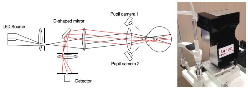
Left: Schematic of the illumination and measurement arms. Right: Photograph of the device mounted on an ophthalmic instrument base for the measurement of human eyes.
The source is separated in 2 concentric zones, a disk corresponding to visual angle of 3 degrees (radius) and an annulus (3 to 8 degrees). In both zones, LEDs are square-wave temporally modulated at 483 Hz and 769 Hz for the peripheral and central areas respectively. A slit-like diaphragm in the illumination arm is conjugated to the pupil plane of the measured eye limiting illumination through the upper part. Although the total power of the source exceeds 2W the diaphragm limits the power delivered to the eye to 90μW (corneal plane). Light reflected from the central part of the fundus (~1 degree) is sensed with a silicon photomultiplier device (Excelitas, Waltham, MA, USA) through a slit-like diaphragm conjugated with the lower part of the pupil to avoid overlapping of the illumination and measurement paths. The Fourier transform of the signal reveals the contribution of the annulus and the disk in the reflected signal. The modulation frequencies were selected so that their harmonic content is well below the sampling frequency (48kHz) of the data acquisition interface (USB6009 – National Instruments, Austin TX, USA).
The separation of the illumination and sensing arms requires accurate positioning of the instrument with respect to the pupil of the eye and conjugation of the diaphragms with the pupil plane (Fig. 2). During optical design, given also the expected anatomical variability of the human eye it was estimated that the tolerance in the axial positioning of the eye with respect to the instrument was on the order of 1 mm.
Fig. 2.
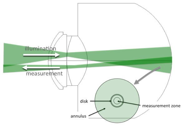
Illumination and measurement geometry.
To achieve this level of accuracy a dual camera system was used (as shown in Fig. 3). The operator is presented with a split screen where the upper and lower halves are displaying video from two cameras that have their axes intersecting at the conjugate plane of the diaphragms. As the cameras are positioned at an angle (approximately 30 degrees) with respect to the instrument axis, the video frames are undergoing a spatial transformation (horizontal stretching) to rectify the image of the eye. The user is required to position the instrument with respect to the eye so that the disparity between the two halves is minimized.
Fig. 3.
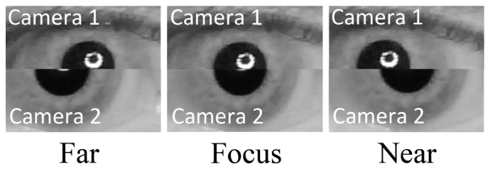
Split video method for axial positioning of the instrument with respect to the eye’s pupil.
Signal acquisition and analysis
A PIC microcontroller circuit generates the modulating signals and triggers data acquisition. A graphical user interface performing video processing and display, data acquisition and data analysis was developed using MATLAB (The Mathworks Inc., Natick, MA). Each measurement has 250msec duration. Figure 4 shows a typical signal and its Fourier transform. The system is designed to detect light received only from the central part of the disk. The smaller signal associated to the annulus is a result of light scattering that deflects light from the annulus to the center of the disk. It must be noted that small refractive errors or aberrations are theoretically not contributing to this signal as the dimensions of the PSF associated to these errors is much smaller than the spatial separation between the edges of the annulus and the measurement zone.
Fig. 4.
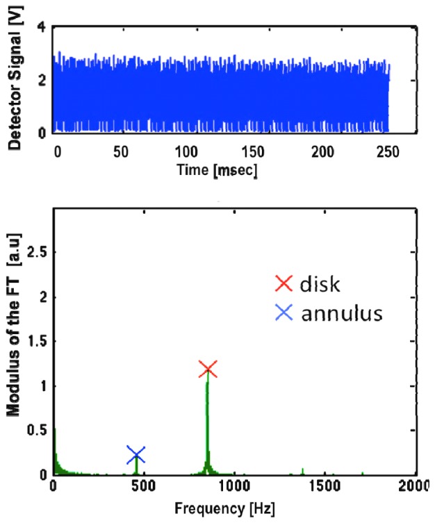
Measured signal and the modulus of its Fourier Transform.
The amplitude of the signals Id and Ia from the disk and the annulus respectively were used to calculate the straylight parameter based on the following considerations.
If PSFdp is the double-pass image of the eye and Io is the uniform intensity of the disk and the annulus, assuming circular symmetry, then the contribution of the annulus to the center of the image is given by:
| (2) |
while the contribution of the disk to the center is
| (3) |
where θ1 is the radial size of the disk and θ2 is the outer angular size of the annulus.
Based on previously described formalism [6], the double pass PSF at the middle of the angular range of the annulus can be calculated by its normalized contribution:
| (4) |
where θs = (θ2-θ1)/2.
From Eq. (4), given also Eq. (1), the straylight parameter is given by:
| (5) |
and the straylight parameter of the eye is therefore half of the value estimated in double pass:
| (6) |
It is interesting to observe that in Eq. (4) the absolute intensity of the annulus and the disk are eliminated. The calculation is performed only based on the relative contributions and source geometry. Similarly, parameters as fundus reflectance or detector gain are eliminated from the calculations. The experimental values for the amplitudes of the fundamental frequencies associated to the disk and the annulus resulting from the Fourier transform can be directly used in Eq. (4).
This approach greatly increases the dynamic range. Even the PSF at an angle of 5.5 degrees is expected to be more than six orders of magnitude lower than the PSF at the peak [8], the recorded signals are within the same order of magnitude (Fig. 4).
The equations above provide the theoretical basis for the calculation of the PSF and the straylight parameter. However, in the instrument the measurement is not performed at an infinitesimally small area in the center of the disk/annulus. Moreover, the finite differences implied in Eq. (4) is an approximation of the derivative required for the exact calculation. Since these approximations are not necessary in a computer-based instrument for the actual measurements a lookup table linking the values of Ia and Ic with S was generated. This numerical calculation involves the 2-dimensional convolution of PSFs with varying amount of straylight (S) and numerical integration over the angular range of the measurement area to derive Ia and Ic. During calibration, baseline values for Ia and Ic were recorded and the system intrinsic straylight was calculated by taking measurements of an artificial eye (a glass lens) that was assumed to have no straylight. These background signals and straylight were subtracted from the values obtained from human eyes.
Validation measurements in human eyes with diffusers
To test the sensitivity and accuracy of the device in human eyes we used photographic diffuser filters (Black ProMist, Tiffen, USA) that have been previously used to simulate straylight in cataract [11]. Ten eyes of ten subjects with no known pathology (e.g. cataract) were measured with four different grades of these filters simulating mild to moderate cataract. The filters were introduced as close as possible to the eye.
3. Results
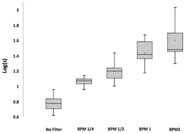
The results of the measurements in human eyes are summarized in Fig. 5.
Fig. 5.
Straylight induced by the filters (expressed as the logarithm of the straylight parameter). BPM1/4, BPM1/2, BPM1 and BPM2 refer to different diffusing filters that were introduced in front of the eyes that are manufactured to introduce progressively more straylight.
The straylight parameter induced by the filters was similar for all subjects and in agreement with values measured separately in the isolated filters.
4. Discussion
A new compact optical instrument suitable for clinical measurement of straylight in the human eye has been developed. The design is based on previous experience with multi-wavelength, high-sensitivity, imaging double-pass systems for the measurement of the wide-angle point-spread function of the eye [6,10]. For clinical application it is important that the measurement is fast, automated and provides information that is directly relevant to clinical practice. Our previous experiments with imaging systems indicated that the optically measured straylight is comparable to that obtained psychophysically [8] and defined the angular range at which optical measurement of straylight is feasible [6]. Later experiments with various wavelengths indicated that optical measurements should be performed preferably near the peak of the spectral sensitivity of the eye [10].
This new instrument may be a step towards the comprehensive evaluation of the optics of the human eye beyond refraction and high-order aberrations. There are several potential clinical applications such as early diagnosis of cataract, the study of corneal healing or humors transparency.
Acknowledgments
This work was supported by ITN OpAL (PITN-GA-2010-264605) and by European Research Council Advanced Grant ERC-2013-AdG-339228 (SEECAT) to P. Artal
References and links
- 1.Holladay L. L., “The fundamentals of glare and visibility,” J. Opt. Soc. Am. 12(4), 271–319 (1926). 10.1364/JOSA.12.000271 [DOI] [Google Scholar]
- 2.Vos J. J., “Disability glare - a state of the art report,” CIEJ 3(2), 39–53 (1984). [Google Scholar]
- 3.Franssen L., Coppens J. E., van den Berg T. J., “Compensation comparison method for assessment of retinal straylight,” Invest. Ophthalmol. Vis. Sci. 47(2), 768–776 (2006). 10.1167/iovs.05-0690 [DOI] [PubMed] [Google Scholar]
- 4.Santamaría J., Artal P., Bescós J., “Determination of the point-spread function of human eyes using a hybrid optical-digital method,” J. Opt. Soc. Am. A 4(6), 1109–1114 (1987). 10.1364/JOSAA.4.001109 [DOI] [PubMed] [Google Scholar]
- 5.Artal P., Marcos S., Navarro R., Williams D. R., “Odd aberrations and double-pass measurements of retinal image quality,” J. Opt. Soc. Am. A 12(2), 195–201 (1995). 10.1364/JOSAA.12.000195 [DOI] [PubMed] [Google Scholar]
- 6.Ginis H. S., Pérez G. M., Bueno J. M., Artal P., “The wide-angle point spread function of the human eye reconstructed by a new optical method,” J. Vis. 12(3), 20 (2012). 10.1167/12.3.20 [DOI] [PubMed] [Google Scholar]
- 7.Stiles W. S., “The effect of glare on the brightness difference threshold,” Proc. R. Soc. Lond., B 104(731), 322 (1929). 10.1098/rspb.1929.0012 [DOI] [Google Scholar]
- 8.Vos J. J., van den Berg T. J., “Report on disability glare,” CIE Collection 135, 1–9 (1999). [Google Scholar]
- 9.Coppens J. E., Franssen L., van den Berg T. J., “Wavelength dependence of intraocular straylight,” Exp. Eye Res. 82(4), 688–692 (2006). 10.1016/j.exer.2005.09.007 [DOI] [PubMed] [Google Scholar]
- 10.Ginis H. S., Perez G. M., Bueno J. M., Pennos A., Artal P., “Wavelength dependence of the ocular straylight,” Invest. Ophthalmol. Vis. Sci. 54(5), 3702–3708 (2013). 10.1167/iovs.13-11697 [DOI] [PubMed] [Google Scholar]
- 11.de Wit G. C., Franssen L., Coppens J. E., van den Berg T. J., “Simulating the straylight effects of cataracts,” J. Cataract Refract. Surg. 32(2), 294–300 (2006). 10.1016/j.jcrs.2006.01.048 [DOI] [PubMed] [Google Scholar]


