Abstract
Efficient and noninvasive generation of cavitation bubbles in soft tissue is a challenging task due to the lack of cavitation nuclei (i.e., pre-existing gas bubbles). In this study, we present a method to generate and enhance cavitation activity based on the utilization of two consecutive ultrasound waves at different frequencies. First, a high frequency (5 MHz) high intensity focused ultrasound (HIFU) wave was applied to a tissue-mimicking phantom to induce a rapid temperature rise in the ultrasound focal region. Immediately following the high frequency HIFU wave, a low frequency (1 MHz) HIFU wave was applied to the same focal region to induce acoustic cavitation. We found that cavitation activity was enhanced when the temperature in the tissue-mimicking phantom was first elevated by the high frequency HIFU wave. The enhancement was greater when a higher intensity of high frequency HIFU wave was applied. This result may be due to the temporary super-saturation of air in the initially air-saturated test samples and the reduction of surface tension at an elevated temperature.
Acoustic cavitation can produce a range of mechanical and thermal effects that may find important biomedical applications. For example, ultrasound-assisted thrombolysis, which has been developed to treat complications such as deep vein thrombosis, acute pulmonary embolism, and stroke, heavily relies on the produced cavitation to dissolve excessive blood clots.1–12 Another example is bubble-enhanced heating during high intensity focused ultrasound (HIFU) therapy. HIFU, being the only truly noninvasive form of localized ablative therapy, is rapidly emerging as a promising modality for the treatment of deep-seated solid tumors. HIFU therapy can benefit from the rapid and highly localized heat deposition around cavitation.13–18 Acoustic cavitation can also enhance the transport of molecules across inaccessible interfaces and facilitate drug and gene uptake by cells through a process called sonoporation.19–25 The localized mechanical impact associated with acoustic cavitation has been recognized as an important factor in sonoporation. The transient disruption of the cell membrane induced by acoustic cavitation during sonoporation effectively increases the cell membrane permeability and permits transport of extracellular compounds that otherwise cannot penetrate through the membranes of viable cells.
Although acoustic cavitation plays a key role in many biomedical applications, a significant barrier is that pre-existing nucleation sites, i.e., pre-existing gas bubbles, for cavitation are not always present in most tissues in vivo. In order to generate cavitation in vivo with high efficiency, high intensity ultrasound with relatively low frequency is employed. The advantage of these techniques is that they can generate cavitations quickly and noninvasively; however, these techniques may induce unwanted damages.11 In addition, the onset and efficiency of cavitation is very difficult to control due to tissue heterogeneity. In order to better control cavitation location and easily nucleate cavitation, cavitation nuclei are frequently delivered to the target region. For example, both ultrasound contrast agents (UCAs)26–31 and nanoparticles have been studied as methods to deliver cavitation nuclei into the target region.19 The use of UCAs and nanoparticles, however, requires systematic injection of foreign particles into the blood stream and has many concerns regarding the toxicity, efficiency, emboli formation, etc.
The current study presents a dual-frequency HIFU method to effectively and noninvasively induce cavitation in a tissue-mimicking phantom. Several recent studies have been focused on enhancing cavitation activity by using ultrasound waves with a mix of two or more frequencies.32–34 In the current study, instead of mixing two ultrasound frequencies and using them at the same time, we employ two consecutive ultrasound pulses at different frequencies. This method is based on a clear mechanism, which is enhanced cavitation activity at an elevated temperature. It is well known that air solubility decreases as temperature increases. If the temperature of an initially air-saturated sample is raised, the sample will become super-saturated with air. The air molecules dissolved in the sample will become unstable because of the super-saturation, and cavitation can then be easily produced. This mechanism can be applied to human tissue because human body liquid is saturated with air molecules such as nitrogen. Even in a well degassed environment, an elevated temperature can improve the chance for air molecules to escape from the surrounding medium and form bubbles. Additionally, vapor pressure increases and surface tension reduces as temperature elevates, further improving the chance of cavitation.
In the current dual-frequency method, high frequency HIFU waves will be applied to the tissue phantom to induce rapid temperature increase at the focal zone. Then, low-frequency ultrasound waves will be delivered to the same region to induce cavitation. The current dual-frequency HIFU technique provides a convenient way to enhance cavitation by raising the target temperature with noninvasive ultrasound.
Figure 1 shows the system schematic used for the experiments. Ultrasound signals, which could have either 1-MHz or 5-MHz frequency, were generated by a computer controlled (through a LabView code) function generator (HP33250A, Agilent Technologies, Santa Clara, CA) and directed to a radio frequency power amplifier (350L, ENI Technology, Inc., Rochester, NY). After the power amplifier, the signals were sent to two homemade filters: a low-pass filter (cutoff frequency: 3 MHz) and a high-pass filter (cutoff frequency: 3 MHz). The purpose of using these two filters was to protect HIFU transducers so that each transducer only operated at the frequency for which it was designed. Therefore, the 1-MHz signal was sent to a 1-MHz HIFU transducer (H-102, Sonic Concepts, Bothell, WA), and the 5-MHz signal to a 5-MHz HIFU transducer (SU-108-013, Sonic Concepts, Bothell, WA). A 10-MHz passive cavitation detector (PCD) (V315, Olympus-NDT, Waltham, MA) was used to detect the resulting cavitation signals. The detected PCD signals were received by a data acquisition system (GageScope, CS21G8-256MSn Gage, Lockport, IL) after pre-amplification and collected by a personal computer (PC). A 10-MHz high-pass filter was used to remove contributions from the HIFU frequencies to ensure that the detected signals were mainly received from broadband acoustic emissions of cavitation. All three ultrasound transducers, including 1-MHz HIFU transducer, 5-MHz HIFU transducer, and the PCD, were carefully aligned to be confocal. The alignment process was guided by a point target with a diameter of 0.5 mm. A 50-μm diameter T-type thermocouple was placed in a location which is 0.5 mm off the focal spot to monitor the temperature. During the experiment, all the transducers and the thermocouple were immersed in a tank filled with degassed, deionized water.
FIG. 1.
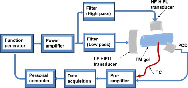
System schematic. HF: high frequency; LF: low frequency; TM: tissue-mimicking; and TC: thermocouple.
In the experiment, an agar-based tissue phantom was used.13 The agar phantom was prepared by dissolving 18 g of agar in 600 ml boiling water, adding the 24 g of graphite powder as absorbers and scatterers, and then allowing the solution to gel in a refrigerator. The thermocouple was imbedded in the prepared agar phantom before the phantom solidified. The tissue phantom was then immersed in air-saturated water for at least two days to create an air-saturated tissue-mimicking sample. Then, the phantom was placed in the water tank for the following experiments.
During the experiment, a tone burst was sent from the function generator. The tone burst consisted of a 2-s 5-MHz continuous wave (CW) signal followed immediately by a 2-s 1-MHz signal. The purpose of the 5-MHz signal was to induce a rapid temperature rise in the focal region, and then the 1-MHz signal was sent to the same region to induce cavitation, which was monitored by the PCD. Both 5-MHz and 1-MHz transducers were first calibrated by a standard needle hydrophone (0.5 mm Needle hydrophone SN 1462, Precision Acoustics, Dorchester, UK). Then, focal pressures were determined through an acoustic calibration process by combining a finite difference time domain code and experiment measurements as described by Huang et al.35
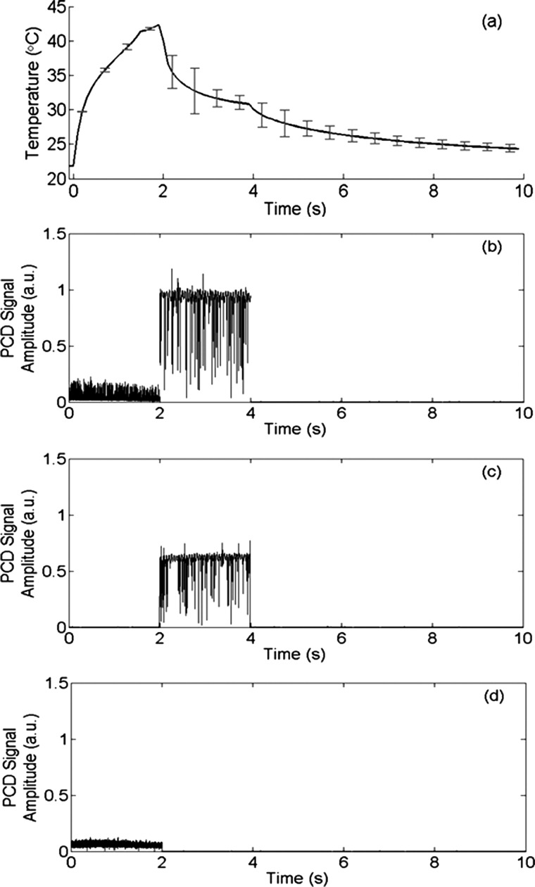
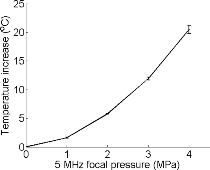
An example of the temperature measured by the thermocouple is presented in Figure 2(a). For this result, the focal pressure was 4 MPa for the 5-MHz CW signal and 3 MPa for the 1-MHz CW signal. During the first 2 s, a rapid temperature increase was induced by the 5-MHz signal. When the signal was switched to 1 MHz, the temperature dropped because the heating rate at 1 MHz was significantly lower than that at 5 MHz. Figure 2(b) shows the corresponding peak cavitation signal detected by the PCD. The cavitation signal showed a nearly zero peak signal level during the first 2-s when the 5-MHz signal was used, and then a very strong peak signal level when the frequency was switched to 1 MHz. The strong signal detected by the PCD indicated strong cavitation activities when the signal frequency was switched to 1 MHz. The measured temperature showed a fairly moderate temperature increase, which was far less than the boiling temperature, and therefore the detected cavitation was not a result of boiling, but a result of ultrasound and tissue phantom interaction. On the other hand, this result also confirmed that the cavitation pressure threshold for the 5-MHz signal was higher than 4 MPa because the cavitation signal was nearly zero when the 5-MHz signal was sonicating the focal zone. Since the highest focal pressure of the 5-MHz signal was 4 MPa in the current study, only heating effect would be expected from the 5-MHz signal. In other words, the 5-MHz signal would raise the temperature in the focal zone without cavitating. Figures 2(c) and 2(d) show the control experiment results where only one frequency was used. Figure 3 shows the measured temperature increase as a function of the focal pressure of the 5-MHz signal. The measured temperature demonstrated a nice quadratic increase as the pressure increased, further confirming that there were no cavitation activities, which would otherwise induce a temperature increase at a rate much faster than a quadratic rate.16,18
FIG. 2.
(a) Temperature measured by the thermocouple; (b) the corresponding cavitation signal detected by the PCD; (c) PCD signal when only 1 MHz ultrasound wave was applied; and (d) PCD signal when only 5 MHz ultrasound wave was applied. PCD signal is in arbitrary unit. Error bars in (a) are standard deviations of five measurements.
FIG. 3.
Temperature increase induced by the 5-MHz signal at different focal pressures. Error bars are standard deviations of five measurements.
To quantify cavitation activity, we defined a cavitation power for the 1-MHz signal as the mean square of the PCD signal when the 1-MHz ultrasound signal was applied. Figure 4 shows the calculated cavitation power as a function of ultrasound focal pressure of the 5-MHz signal, which was used prior to the 1-MHz signal to induce the rapid temperature increase in the focal region. When the 1-MHz focal pressure was relatively low (0.5, 1, and 1.5 MPa), the 1-MHz cavitation power was nearly a constant when the 5-MHz focal pressure increased. The nearly constant 1-MHz cavitation power was due to the fact that both 1 and 5-MHz signals were under cavitation pressure thresholds for the corresponding ultrasound frequencies. Therefore, no significant cavitation signals were detected by the PCD under these pressures.
FIG. 4.
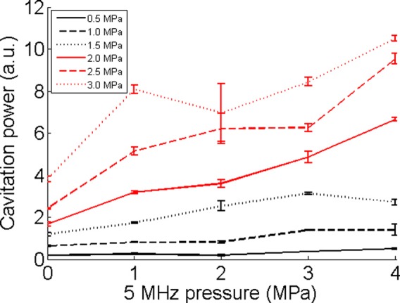
Cavitation powers for different 1-MHz focal pressures. It is presented as a function of the 5-MHz focal pressure, which was used prior to the 1-MHz signals. The figure legends are for the 1-MHz signals. Cavitation power is in arbitrary unit. Error bars show standard deviations of five measurements.
When the focal pressure of the 1-MHz signal was at 2 MPa or higher, which was higher than the cavitation pressure threshold (∼1.7 MPa for the tissue phantom) of 1-MHz signal, a general trend of increase in cavitation power was observed as the 5-MHz focal pressure increased. Since an increased 5-MHz pressure would induce an increased focal temperature, the results demonstrated that cavitation activity at 1 MHz was enhanced as the focal temperature increased. For each fixed 5-MHz focal pressure, the cavitation power increased as the 1-MHz focal pressure increased, which was expected since stronger ultrasound pressure would induce stronger cavitation activities.
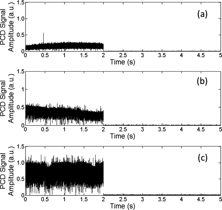
To separately confirm that cavitation can be enhanced at an elevated temperature during HIFU, cavitation activity was measured in tissue-mimicking gels at different temperatures. During the HIFU experiment, a warm water bath was heated to the pre-determined temperature, and then the gel was placed in the water bath for ∼20 min to allow the sample to reach thermal equilibrium (confirmed by a thermocouple). Then, a 5-MHz, 2-s HIFU tone burst was delivered into the gel to induce cavitation. The detected PCD signals are presented in Figure 5 and confirm that cavitation activity increased as the temperature was elevated under the same ultrasound parameters.
FIG. 5.
Cavitation activity at different temperatures: (a) 20 °C, (b) 30 °C, and (c) 40 °C. Focal pressure was 6 MPa.
In soft tissue, thermal effect is the dominant effect for high frequency ultrasound, whereas mechanical (such as cavitation) effect is mainly related to low frequency ultrasound. The combination of high and low frequency ultrasound allows us to raise the local tissue temperature and then induce cavitation. The current dual-frequency method takes the advantages of both thermal and mechanical effects of ultrasound at different frequencies and achieves better outcomes. We used a 1-MHz ultrasound signal as the low frequency signal and a 5-MHz ultrasound signal as the high frequency signal. These frequencies are not optimized. For the high frequency signal, we expect that a higher frequency ultrasound such as 10 MHz could produce better results because the heating effect will be more dominant, and a higher temperature increase can be achieved rapidly. For low frequency, we expect a lower frequency such as 100 kHz may be better to produce cavitation because the cavitation pressure threshold reduces as ultrasound frequency decreases.
It is also worth noting that the cavitation zone will be defined by the size of the high frequency ultrasound focal zone because that region is where the temperature rise occurs. This feature can potentially benefit medical applications because high frequency ultrasound, such as 10 MHz, can have a focal zone as small as 1 mm, and therefore damages to the surrounding tissue may be avoided.
Finally, during the heating stage, if the focal region is heated to near boiling temperature, boiling cavitation36 can be generated before applying the low frequency ultrasound wave. The boiling cavitation may accompany permanent thermal damages to the surrounding soft tissue. Therefore, the initial temperature rise induced by the high frequency ultrasound wave needs to be carefully controlled if thermal damages are unwanted.
Acknowledgments
This study was supported in part by NIH Grant No. 1R03EB015077-01A1.
References
- 1.Luo H., Steffen W., Cercek B., Arunasalam S., Maurer G., and Siegel R. J., Am. Heart J. 125(6), 1564–1569 (1993). 10.1016/0002-8703(93)90741-Q [DOI] [PubMed] [Google Scholar]
- 2.Wright C., Hynynen K., and Goertz D., Invest. Radiol. 47(4), 217–225 (2012). 10.1097/RLI.0b013e31823cc75c [DOI] [PMC free article] [PubMed] [Google Scholar]
- 3.Parikh S., Motarjeme A., McNamara T., Raabe R., Hagspiel K., Benenati J. F., Sterling K., and Comerota A., J. Vasc. Interventional Radiol. 19(4), 521–528 (2008). 10.1016/j.jvir.2007.11.023 [DOI] [PubMed] [Google Scholar]
- 4.Haar G. ter, Eur. J. Ultrasound 9(1), 3–9 (1999). 10.1016/S0929-8266(99)00013-0 [DOI] [PubMed] [Google Scholar]
- 5.Holland C. K., Vaidya S. S., Datta S., Coussios C.-C., and Shaw G. J., Thromb. Res. 121(5), 663–673 (2008). 10.1016/j.thromres.2007.07.006 [DOI] [PMC free article] [PubMed] [Google Scholar]
- 6.Siegel R. J. and Luo H., Ultrasonics 48(4), 312–320 (2008). 10.1016/j.ultras.2008.03.010 [DOI] [PubMed] [Google Scholar]
- 7.Tsivgoulis G. and Alexandrov A., Stroke 39(5), 1404–1405 (2008). 10.1161/STROKEAHA.107.505594 [DOI] [PubMed] [Google Scholar]
- 8.Tsivgoulis G., Culp W. C., and Alexandrov A. V., Ultrasonics 48(4), 303–311 (2008). 10.1016/j.ultras.2007.11.008 [DOI] [PubMed] [Google Scholar]
- 9.Molina C. A., Ribo M., Rubiera M., Montaner J., Santamarina E., Delgado-Mederos R., Arenillas J. F., Huertas R., Purroy F., Delgado P., and Alvarez-Sabin J., Stroke 37(2), 425–429 (2006). 10.1161/01.STR.0000199064.94588.39 [DOI] [PubMed] [Google Scholar]
- 10.Maxwell A. D., Cain C. A., Duryea A. P., Yuan L., Gurm H. S., and Xu Z., Ultrasound Med. Biol. 35(12), 1982–1994 (2009). 10.1016/j.ultrasmedbio.2009.07.001 [DOI] [PMC free article] [PubMed] [Google Scholar]
- 11.Maxwell A. D., Owens G., Gurm H. S., Ives K., D. D. Myers, Jr. , and Xu Z., J. Vasc. Interventional Radiol. 22(3), 369–377 (2011). 10.1016/j.jvir.2010.10.007 [DOI] [PMC free article] [PubMed] [Google Scholar]
- 12.Cui H. and Yang X., J. Acoust. Soc. Am. 133(2), EL123–EL128 (2013). 10.1121/1.4778375 [DOI] [PMC free article] [PubMed] [Google Scholar]
- 13.Yang X., Ph.D. dissertation, Boston University, 2003. [Google Scholar]
- 14.Yang X. M., Roy R. A., and Holt R. G., J. Acoust. Soc. Am. 116(6), 3423–3431 (2004). 10.1121/1.1823251 [DOI] [PubMed] [Google Scholar]
- 15.Hynynen K., Ultrasound Med. Biol. 17(2), 157–169 (1991). 10.1016/0301-5629(91)90123-E [DOI] [PubMed] [Google Scholar]
- 16.Holt R. G. and Roy R. A., Ultrasound Med. Biol. 27(10), 1399–1412 (2001). 10.1016/S0301-5629(01)00438-0 [DOI] [PubMed] [Google Scholar]
- 17.Hanajiri K., Maruyama T., Kaneko Y., Mitsui H., Watanabe S., Sata M., Nagai R., Kashima T., Shibahara J., Omata M., and Matsumoto Y., Hepatol. Res. 36(4), 308–314 (2006). 10.1016/j.hepres.2006.08.013 [DOI] [PubMed] [Google Scholar]
- 18.Yang X. M. and Church C. C., Acoust. Res. Lett. Online 6(3), 151–156 (2005). 10.1121/1.1897824 [DOI] [Google Scholar]
- 19.Coussios C. C. and Roy R. A., Annu. Rev. Fluid Mech. 40, 395–420 (2008). 10.1146/annurev.fluid.40.111406.102116 [DOI] [Google Scholar]
- 20.Bao S. P., Thrall B. D., and Miller D. L., Ultrasound Med. Biol. 23(6), 953–959 (1997). 10.1016/S0301-5629(97)00025-2 [DOI] [PubMed] [Google Scholar]
- 21.Miller D. L., Pislaru S. V., and Greenleaf J. F., Somatic Cell Mol. Genet. 27(1–6), 115–134 (2002). 10.1023/A:1022983907223 [DOI] [PubMed] [Google Scholar]
- 22.Marmottant P. and Hilgenfeldt S., Nature 423(6936), 153–156 (2003). 10.1038/nature01613 [DOI] [PubMed] [Google Scholar]
- 23.Prentice P., Cuschierp A., Dholakia K., Prausnitz M., and Campbell P., Nat. Phys. 1(2), 107–110 (2005). 10.1038/nphys148 [DOI] [Google Scholar]
- 24.Fan Z., Liu H., Mayer M., and Deng C. X., Proc. Natl. Acad. Sci. U. S. A. 109(41), 16486–16491 (2012). 10.1073/pnas.1208198109 [DOI] [PMC free article] [PubMed] [Google Scholar]
- 25.Zhou Y., Yang K., Cui J., Ye J. Y., and Deng C. X., J. Controlled Release 157(1), 103–111 (2012). 10.1016/j.jconrel.2011.09.068 [DOI] [PMC free article] [PubMed] [Google Scholar]
- 26.Luo W., Zhou X. D., Tian X., Ren X. L., Zheng M. J., Gu K. J., and He G. B., Adv. Ther. 23(6), 861–868 (2006). 10.1007/BF02850207 [DOI] [PubMed] [Google Scholar]
- 27.Tung Y. S., Liu H. L., Wu C. C., Ju K. C., Chen W. S., and Lin W. L., Ultrasound Med. Biol. 32(7), 1103–1110 (2006). 10.1016/j.ultrasmedbio.2006.04.005 [DOI] [PubMed] [Google Scholar]
- 28.Yu T. H., Xiong S. H., Mason T. J., and Wang Z. B., Ultrason. Sonochem. 13(2), 143–149 (2006). 10.1016/j.ultsonch.2005.02.001 [DOI] [PubMed] [Google Scholar]
- 29.Stride E. P. and Coussios C. C., Proc. Inst. Mech. Eng., Part H 224(H2), 171–191 (2010). 10.1243/09544119JEIM622 [DOI] [PubMed] [Google Scholar]
- 30.Zhang P. and Porter T., Ultrasound Med. Biol. 36(11), 1856–1866 (2010). 10.1016/j.ultrasmedbio.2010.07.001 [DOI] [PubMed] [Google Scholar]
- 31.Ho V. H. B., Smith M. J., and Slater N. K. H., Ultrasound Med. Biol. 37(1), 169–175 (2011). 10.1016/j.ultrasmedbio.2010.09.007 [DOI] [PubMed] [Google Scholar]
- 32.Baac H. W., Lee T., Ok J. G., Hall T., and Guo L. J., Appl. Phys. Lett. 103(23), 234103 (2013). 10.1063/1.4836315 [DOI] [Google Scholar]
- 33.Guo S., Jing Y., and Jiang X., IEEE Trans. Ultrason. Ferroelectr. Freq. Control 60(8), 1699–1707 (2013). 10.1109/TUFFC.2013.2751 [DOI] [PubMed] [Google Scholar]
- 34.Feng R., Zhao Y. Y., Zhu C. P., and Mason T. J., Ultrason. Sonochem. 9(5), 231–236 (2002). 10.1016/S1350-4177(02)00083-4 [DOI] [PubMed] [Google Scholar]
- 35.Huang J., Holt R. G., Cleveland R. O., and Roy R. A., J. Acoust. Soc. Am. 116(4), 2451–2458 (2004). 10.1121/1.1787124 [DOI] [PubMed] [Google Scholar]
- 36.Farny C. H., Holt R. G., and Roy R. A., Ultrasound Med. Biol. 35(4), 603–615 (2009). 10.1016/j.ultrasmedbio.2008.09.025 [DOI] [PubMed] [Google Scholar]


