Abstract
Purpose:
3D optical surface imaging has been applied to patient positioning in radiation therapy (RT). The optical patient positioning system is advantageous over conventional method using cone-beam computed tomography (CBCT) in that it is radiation free, frameless, and is capable of real-time monitoring. While the conventional radiographic method uses volumetric registration, the optical system uses surface matching for patient alignment. The relative accuracy of these two methods has not yet been sufficiently investigated. This study aims to investigate the theoretical accuracy of the surface registration based on a simulation study using patient data.
Methods:
This study compares the relative accuracy of surface and volumetric registration in head-and-neck RT. The authors examined 26 patient data sets, each consisting of planning CT data acquired before treatment and patient setup CBCT data acquired at the time of treatment. As input data of surface registration, patient’s skin surfaces were created by contouring patient skin from planning CT and treatment CBCT. Surface registration was performed using the iterative closest points algorithm by point–plane closest, which minimizes the normal distance between source points and target surfaces. Six degrees of freedom (three translations and three rotations) were used in both surface and volumetric registrations and the results were compared. The accuracy of each method was estimated by digital phantom tests.
Results:
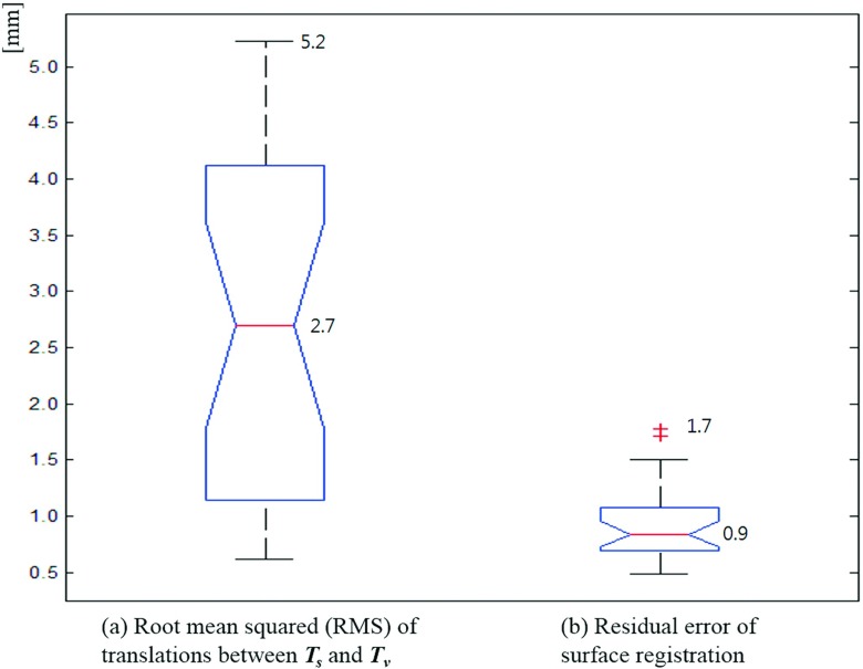
Based on the results of 26 patients, the authors found that the average and maximum root-mean-square translation deviation between the surface and volumetric registrations were 2.7 and 5.2 mm, respectively. The residual error of the surface registration was calculated to have an average of 0.9 mm and a maximum of 1.7 mm.
Conclusions:
Surface registration may lead to results different from those of the conventional volumetric registration. Only limited accuracy can be achieved for patient positioning with an approach based solely on surface information.
Keywords: surface registration, optical surface imaging, patient setup, patient positioning, radiotherapy
1. INTRODUCTION
Recently, ceiling mounted 3D optical surface imaging (OSI) devices have been applied to patient setup in radiation therapy (RT). The patient surface data are registered (matched) to a surface model captured in the simulation room or contoured from computed tomography (CT) data. Compared with the conventional method of radiographic imaging for patient setup, OSI has the advantages of being radiation free and providing continuous, near real-time data.1 The OSI systems have been investigated to replace invasive stereotactic frames for stereotactic radiosurgery (SRS).1–3 The representative systems of OSI-guided RT are AlignRT (VisionRT Co., England)4 and Sentinel (C-RAD Co., Sweden).5 These systems allow continuous noninvasive real-time patient motion monitoring.
Some research has reported on the clinical outcomes and the accuracy of OSI when it is applied in RT. Nath et al.6 and Pan et al.,7 investigated the clinical outcomes of frameless surface imaging guided radiosurgery to treat brain metastases. They concluded that the resultant accuracy of OSI is comparable to that of conventional frame-based stereotactic radiosurgery, but with greater patient comfort. Other groups have investigated the feasibility of OSI for breast and prostate RT.8,9 Cervino et al. validated that OSI system accuracy was within 1 mm in displacement and 1° in rotation compared with an infrared optical tracking system.10 Similar results were found in the research of Peng et al. through comparison with the Elekta kV cone-beam CT (CBCT) and the Varian frameless SonArray.11 Li et al. showed the OSI accuracy was improved with a patient-specific head mold and a dental mouthpiece in a 1D phantom test.12 However, these studies rely on a phantom test or a limited number of subjects or focus only on the feasibility of clinical applications of OSI. Recent research on the OSI accuracy using patients can be found in Refs. 13–16, which argue OSI may reduce CBCT scan frequency for patient setup where tumor location is fixed relative to the surface although interfraction error is relatively large. Here, we evaluate the accuracy of surface registration by comparing registration results with that of a conventional volumetric registration method for 26 head-and-neck cases based on simulation experiments. The simulation study using RT patients can estimate the surface registration’s theoretical accuracy compared to the volumetric registration without additional error factors. This research provides an objective assessment of the accuracy of patient positioning based on surface information and sheds useful insight into the validity of surface imaging in radiation therapy.
2. METHOD
2.A. General description
In order to compare surface and volumetric registration, we investigated retrospective 26 sets of planning CT and CBCT data for head-and-neck RT. The CBCT data were acquired on a Varian TrueBeam Linac (Varian Medical Systems, Palo Alto, CA)17 with tube current of 20 mA at 80 kVp, and the patient was fixed with an immobilization mask. According to the study of Stieler et al.,16 there was no significant difference of error among head-and-neck, thoracic, and pelvic targets in OSI-based patient setup for RT. For each set of data, one CBCT acquired in the course of their treatment was registered to the planning CT data using both volumetric and surface registration algorithms. The output of these registration algorithms is a set of translations and rotations that aligns the two data sets. By examining the level of agreement between the two registration approaches, we are able to assess the accuracy of surface registration.
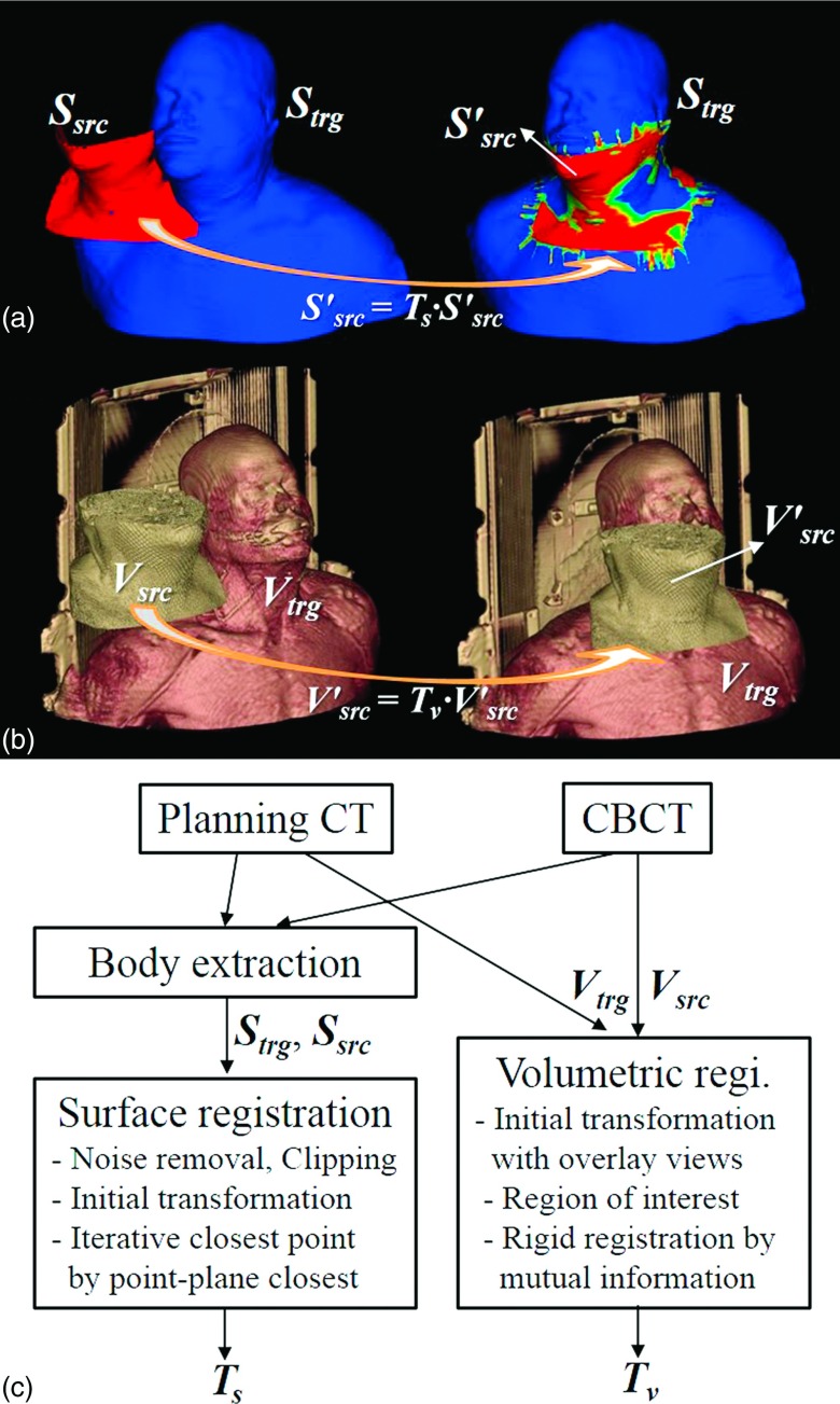
Surface data were extracted from the CT and CBCT by using the contouring module of Eclipse treatment planning system (Varian Medical Systems, Palo Alto, CA).17 We extracted the body surface underneath the immobilization mask using thresholding and morphological image processing such as erosion. The extracted surface is carefully examined visually to make sure it matches the true body surface. The source objects for volumetric and surface registrations were, respectively, the CBCT (Vsrc) and the corresponding surface (Ssrc). The planning CT and the surface extracted therefrom were used as the target volume (Vtrg) and target surface (Strg). The calculated transformations [Tv = (tv,lat, tv,vert, tv,long, rv,pitch, rv,rot, rv,roll) for volumetric registration and Ts = (ts,lat, ts,vert, ts,long, rs,pitch, rs,rot, rs,roll) for surface registration] consist of three translations (lateral, vertical, and longitudinal) and three rotations (pitch, rotation, and roll). The pitch, rotation, and roll are rotations about the lateral, vertical, and longitudinal axes, respectively. Figure 1 depicts the surface and volumetric registrations with sample data and a flowchart.
FIG. 1.
(a) Surface registration. Ssrc: source surface from planning CT, Strg: target surface from treatment CBCT, : transformed source surface calculated by surface registration, Ts: transformation matrix calculated by surface registration, (b) Volumetric registration. Vsrc: source volume data from planning CT, Vtrg: target volume data from treatment CBCT, : transformed source volume data by volumetric registration, Tv: transform matrix by volumetric registration, and (c) Flowchart of the surface and volumetric registrations.
2.B. Surface registration
One of the most popular and robust algorithms of surface registration is the iterative closest point (ICP).18,19 The ICP algorithm iteratively revises the transformation to minimize the difference between two point clouds. The ICP based on point–plane closest method18,20 minimizes the distance between the source points and the target surface with the normal vectors. The error function E shown is given by
| (1) |
where pi: source points, qi: target points, R: rotation matrix, t: translation vector, and ni: normal vectors.
Linear least-squares function is iteratively minimized to obtain the transformation Ts. At each iteration, the transformation parameters (ts,lat, ts,vert, ts,long, rs,pitch, rs,rot, rs,roll) are estimated and transformed by solving the least-squares problem. We implemented the ICP based on point–plane closest method by modifying the surface registration module of the open source toolkit VTK.21 The initial transformation is defined by a set of three pairs of input points defined by the user. The implemented ICP algorithm then automatically calculates the optimal transformation Ts. Ssrc is transformed by applying Ts to match with Strg as illustrated in Fig. 1(a). Some portions of the surface, such as nostril and mouth, were removed with a mesh editing software RapidForm (3D Systems, Rockhill, SC)22 to reduce unnecessary segmentation error and noise in registration. The posterior side of the surface was deleted because the 3D optical scanner on the ceiling can capture only the anterior side of the patient in common OSI-based IGRT.
2.C. Volumetric registration
While only the points and normals on the surface are used for surface registration, intensity information of all voxels in volume images contributes in volumetric registration. We employed 3D Slicer23,24 for rigid volumetric registration. The volumetric registration of Vsrc to Vtrg consists of the following steps: (1) Loading of multivolume images; (2) Manual transformation in overlay views for initial transformation; (3) Definition of ROI (region of interest) for Vtrg; and (4) IO setting and execution of rigid registration. By maximizing the mutual information25,26 between CBCT and CT images, the registration algorithm yields six transformation parameters, Tv (tv,lat, tv,vert, tv,long, rv,pitch, rv,rot, rv,roll).
2.D. Digital phantom tests
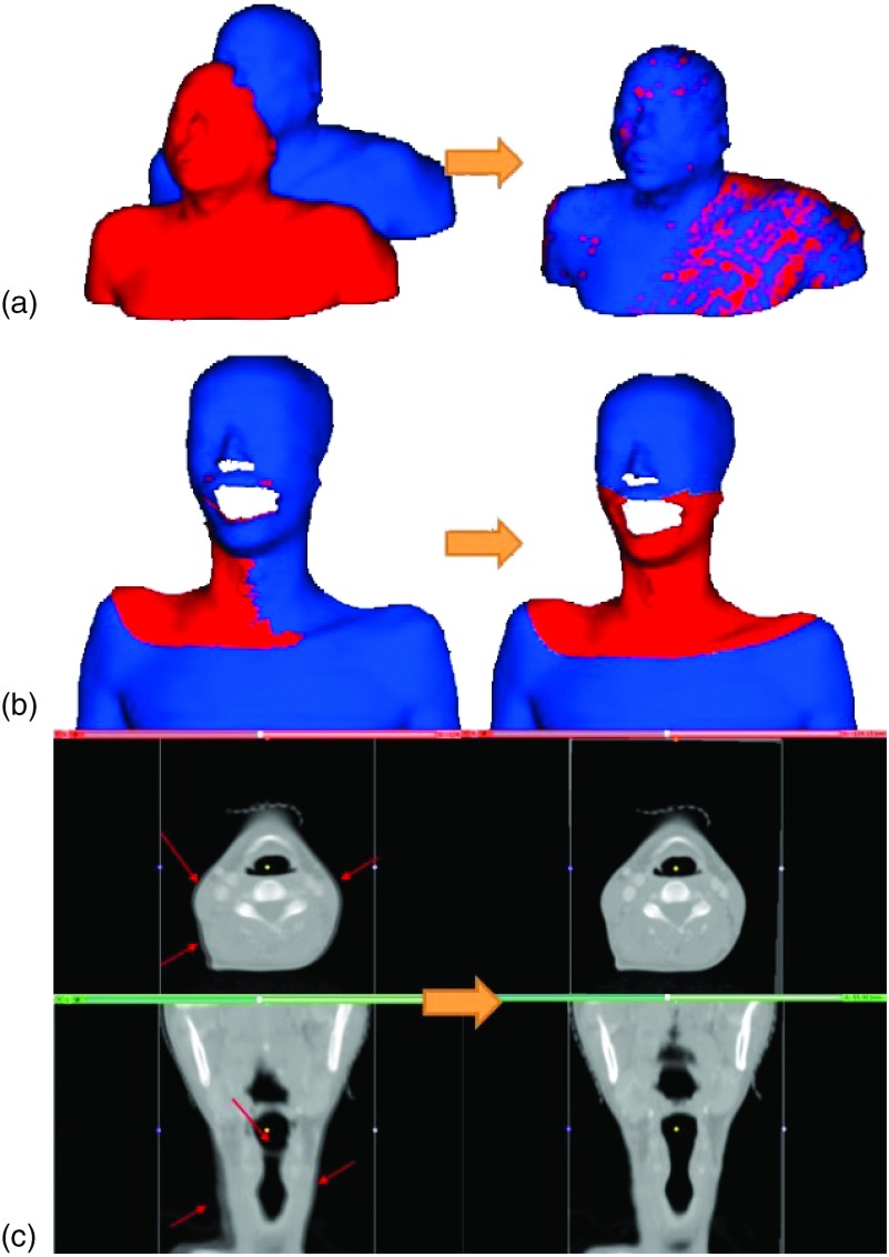
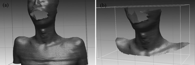
To ensure the performance of the surface and volumetric registration methods, we performed three digital phantom tests and measured the resultant registration errors of the algorithms. First, we transformed a sample patient’s surface (extracted from the planning CT) with known transformation parameters [left panel of Fig. 3(a)]. Transformation parameters were then computed using the registration algorithm described in Sec. 2.B and compared with the known values. As the second test, we simulated a treatment CBCT surface by truncating upper and lower parts beyond the viewing volume of the CBCT and applying a known transformation [right panel of Fig. 2 and left panel of Fig. 3(b)]. This surface was then registered to the unchanged surface and the results were compared. All surface modifications were made in RapidForm.22 Third, as a test of volumetric registration algorithm, we simulated a sample source volume by transforming a planning CT with known parameters. The rigid volumetric registration results obtained using the method described in Sec. 2.C were then compared with the known values.
FIG. 3.
(a) First digital phantom test of surface registration (the sample source surface was created by transforming the target surface with known transformation parameters); (b) Second digital phantom test of surface registration (the target surface is contoured from a patient’s planning CT and the source surface is created by truncating and transforming the target surface); (c) The digital phantom test of volumetric registration—the unmatched parts marked by arrows before the registration (left) were successfully matched after the volumetric registration (right).
FIG. 2.
Digital phantom test data for the surface registration method: (a) a target surface from a sample patient’s planning CT data and (b) a simulated CBCT source surface created by truncating and transforming the target surface in RapidForm (Ref. 22).
2.E. Agreement between the surface and volumetric registrations
We processed data for 26 head-and-neck patients, each consisting of a planning CT and a pretreatment CBCT. Both surface and volumetric registrations were carried out for each case and the resultant registration parameters, Ts and Tv, were compared. The root-mean-square (RMS) differences between two sets of translation parameters of Ts and Tv
| (2) |
are computed. In addition, to assess the accuracy of surface registration, we measured the residual error by averaging the minimum distances between Strg and Ssrc. For every point of Ssrc, the minimum distance to Strg is computed by projecting the point’s normal vector to Strg. The residual error indicates how closely the two surfaces are matched after registration.
3. RESULTS
The implemented ICP algorithm for surface registration provided the optimal transformation parameters for registering Ssrc and Strg within 100 ms on a PC with Intel i7 3.40 GHz CPU and 12 GB memory. This rapid computation suggests that the surface registration can be used for monitoring or tracking patient motion in real-time during treatment. The results from our simulation studies and patient case studies are summarized in the following.
3.A. Digital phantom tests
Surface registration of a testing surface with the corresponding transformed surface reproduced the known transformation parameters with an accuracy better than 0.001 mm or 0.001°. In the second simulation test, similar success was accomplished for the five independent tests. With an intended transformation of Ts (ts,lat, ts,vert, ts,long, rs,pitch, rs,rot, rs,roll) = (−2.0, 2.0, − 1.0, − 1.0, 1.0, − 2.0), for example, our ICP technique yielded transformation parameters of (−1.93, 1.98, −1.04, −0.98, 0.97, −2.01). The RMS error of translation was found to be 0.08 mm. A negligible residual error of 0.01 mm was found after the surface registration. The first and second surface registrations using digital phantoms are shown in Figs. 3(a) and 3(b), respectively.
The digital phantom tests of the volumetric registration also indicated that the submillimeter accuracy is achievable. For a testing transformation of Tv (tv,lat, tv,vert, tv,long, rv,pitch, rv,rot, rv,roll) = (−2.0, 2.0, − 1.0, − 1.0, 1.0, − 2.0), for example, the resultant volumetric registration algorithm yields Tv = (−1.93, 1.99, − 1.03, − 1.00, 0.97, − 2.00). The corresponding RMS error of translation is 0.07 mm. Figure 3(c) shows the overlaid images of the source and target volume before and after the simulation test. It is seen that the unmatched parts (marked in arrows) before the registration were successfully matched after the volumetric registration in Fig. 3(c).
3.B. Comparison between surface registration and volume registration
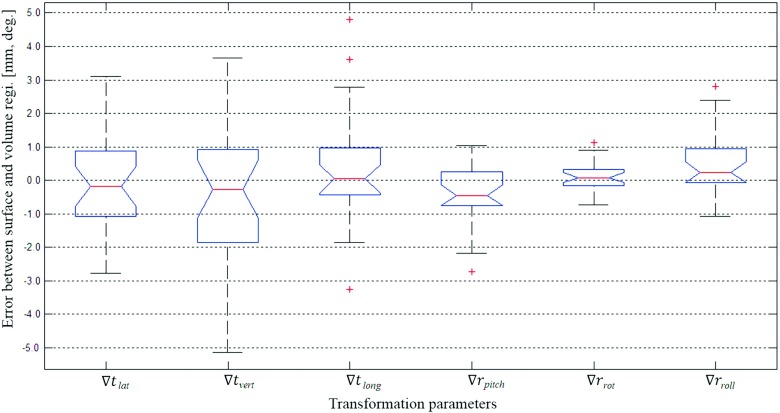
As the main results of this study, Figs. 4 and 5 show the differences between the surface registration (Ts) and the volumetric registration (Tv) parameters for 26 patients. Figure 4 shows the deviation [∇T = (Ts − Tv)] of the surface registration from the volumetric registration for all translation and rotational parameters. The average and standard deviation of ∇T’s each parameter are as follows: ∇tlat = − 0.1 ± 1.4 mm, ∇tvert = − 0.5 ± 2.2 mm, ∇tlong = 0.3 ± 1.7 mm, ∇rpitch = − 0.3 ± 0.9°, ∇rrot = 0.1 ± 0.5°, and ∇rroll = 0.5 ± 0.9°. Figure 5 shows the RMS error between Ts and Tv, and the residual error of the surface registration. The average RMS of the translational error between Ts and Tv was found to be 2.7 mm, while the maximum RMS error was 5.2 mm. The residual error of the surface registration was calculated to have an average of 0.9 mm and a maximum of 1.7 mm.
FIG. 4.
Deviations of the surface registration compared to the volumetric registration, where ∇T = (Ts − Tv), (∇tlat, ∇tvert, ∇tlong, ∇rpitch, ∇rrot, ∇rroll) = (ts,lat − tv,lat, ts,vert − tv,vert, ts,long − tv,long, rs,pitch − rv,pitch, rs,rot − rv,rot, rs,long − rv,long). The central box represents the central 50% of the data (its lower and upper boundary lines are at the 25% and 75% quantile). The central line in the box indicates the median of the data, and the cross marks are the outlier data.
FIG. 5.
(a) RMS error of translation between the surface and volumetric registrations and (b) residual error of surface registration.
4. DISCUSSION
In this study, we compared quantitatively the patient positioning based on surface registration and volumetric registration. Our study indicates that considerable difference between the surface registration (Ts) and the volumetric registration (Tv) could occur. As shown in Fig. 5, although the median values are found to be about zero, the average RMS deviation for translation is 2.7 mm and the worst scenario could be 5.2 mm. It is interesting to point out that error in the vertical direction (anterior–posterior) is usually the largest, probably because only the front part of the patient data was used in surface registration. These results stand in contrast to research reported in Refs. 10–12, probably because previous studies of OSI evaluation are largely phantom studies in ideal environments. Recent patient studies showed similar accuracy errors in OSI patient setup, suggesting the OSI should be carefully used because of the relatively large interfraction variability.13–16 According to the study of Betgen et al.,13 interfraction systematic and random errors are 2.0–5.0 mm and 0.9–2.2 mm for translation and between 0.08° and 1.56° for rotation. Pallotta et al.14 reported mean absolute differences of 2–4 mm in translations and 1°–2° in rotations between OSI and CBCT. Our simulation results are similar level with the previous research’s results using the real OSI systems, thus we can conclude that the surface registration for interfraction patient setup has such inevitable uncertainties compared to the volumetric registration.
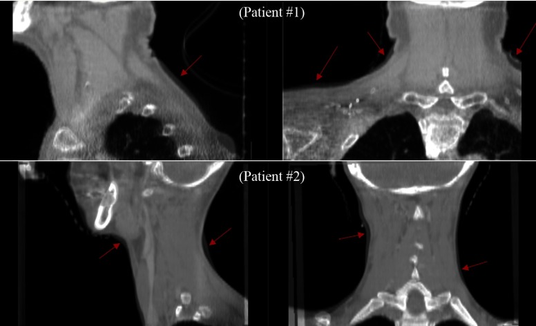
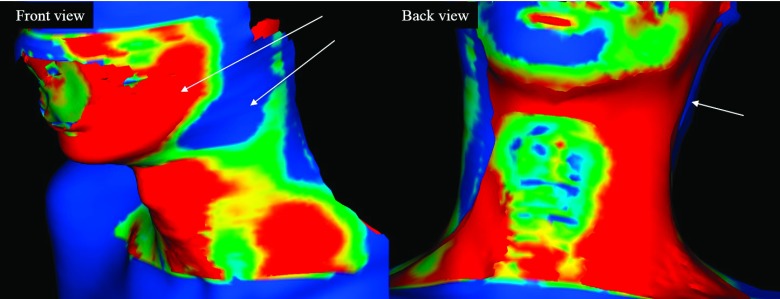
In RT patient setup using surface or volumetric imaging, there are many possible errors due to changes in the patient’s body shape between planning and treatment. To further investigate this issue, we show some snapshots of the registration results. Figure 6 shows the overlay images of planning CT and treatment CBCT for two patients after volumetric registration. The arrows indicate some salient body shape differences between the two different time points of plan ning and treatment. Figure 7 shows the shape differences of the patient’s body after the surface registration. Even though the surface registration found the best match between the planning and treatment surfaces, mismatched regions inside the patients may appear because of the anatomy changes of the patients. The cause of error between Ts and Tv may be largely attributed to two sources. First, the posture of the patient may change significantly from the planning CT scan and the treatment, as shown in Figs. 6 and 7. Second, the patient may experience significant weight loss during the treatment period. Lee et al. reported a median weight loss of 3.3% between the start and completion of treatment, with a daily weight loss ranging between 0.15% and 0.22%.27 Because weight loss can change the external shape of body, especially on the neck, the patient’s body surface at treatment can differ from that of planning CT. As surface registration considers only the external shape of the body while the volumetric registration includes intensity information of internal anatomy, weight loss is likely to have a more pronounced effect on surface registration.
FIG. 6.
Overlapping sectional images of planning CT and treatment CBCT after volumetric registration for two patients. Red arrows indicate the salient changes that have occurred in the volume during radiation treatment for head-and-neck cancer.
FIG. 7.
Color-mapped surface of a patient’s body after surface registration according to the distance error. The arrows indicate error regions between source and target surfaces due to shape changes.
In general, OSI has certain advantages over conventional techniques. However, it seems that its accuracy is guaranteed only if special measures are taken to avoid the potential pitfalls of the approach. To improve the repeatability of patient setup, for instance, Li et al. utilized a patient-specific head-and-neck support mold by CDR Systems28 and a dental mouthpiece.12
The simulation study allows us to quantify the theoretical accuracy of the surface registration method. It is worth to mention that the surfaces used for registration in this study were not obtained from an OSI system such as VisionRT (Ref. 4) or Sentinel5 but rather extracted from CBCT data using contouring software. Further study will be useful to demonstrate the accuracy in using the CBCT-extracted skin surface to represent that from an OSI. The results in this study might also be influenced by CBCT’s limited field of view, imaging parameters, and reconstruction methods. The conventional method of volumetric registration, used as a reference, may also have intrinsic uncertainty. According to the research of Pallotta et al. using the thorax and pelvic regions,14 there was no change in using the extracted surface from the planning CT as a reference (or target surface) instead of the surface from the OSI, which indicates that the difference between the extracted surface and OSI’s surface is negligible. Pallotta et al. reported the observed difference between them was not statistically significant (pelvis p = 0.21 and thorax p = 0.68).
5. CONCLUSION
From our simulation study using 26 head-and-neck RT patients, we conclude that surface registration may lead to results different from that of the conventional volumetric registration. Caution should thus be taken in using an OSI system as the sole modality for patient setup in head-and-neck RT. Additional measures are useful to ensure the accuracy of OSI in RT patient setup.
ACKNOWLEDGMENTS
This research was supported in part by the KIST institutional program (2E24520), the Industrial Strategic technology development program (10035495) funded by the Ministry of Trade, Industry and Energy (MOTIE, KOREA), and the Radiation Safety Research Programs (1305033) through the Nuclear Safety and Security Commission, and the NIH (R01EB016777).
REFERENCES
- 1.Meeks S. L., Tomé W. A., Willoughby T. R., Kupelian P. A., Wagner T. H., Buatti J. M., and Bova F. J., “Optically guided patient positioning techniques,” Semin. Radiat. Oncol. 15(3), 192–201 (2005). 10.1016/j.semradonc.2005.01.004 [DOI] [PubMed] [Google Scholar]
- 2.Djajaputra D. and Li S., “Real-time 3D surface-image-guided beam setup in radiotherapy of breast cancer,” Med. Phys. 32, 65–75 (2005). 10.1118/1.1828251 [DOI] [PubMed] [Google Scholar]
- 3.Baroni G., Riboldi M., Spadea M. F., Tagaste B., Garibaldi C., Orecchia R., and Pedotti A., “Integration of enhanced optical tracking techniques and imaging in IGRT,” J. Radiat. Res. 48, A61–A74 (2007). 10.1269/jrr.48.A61 [DOI] [PubMed] [Google Scholar]
- 4.AlignRT, VisionRT, Inc., http://www.visionrt.com/.
- 5.Sentinel, Catalyst, C-RAD, Inc., http://www.c-rad.se/.
- 6.Nath S. K., Lawson J. D., Wang J. Z., Simpson D. R., Newman C. B., Alksne J. F., Mundt A. J., and Murphy K. T., “Optically guided frameless linac-based radiosurgery for brain metastases: Clinical experience,” J. Neuro-Oncol. 97(1), 67–72 (2010). 10.1007/s11060-009-9989-y [DOI] [PMC free article] [PubMed] [Google Scholar]
- 7.Pan H., Cervino L. I., Pawlicki T., Jiang S. B., Alksne J., Detorie N., Russell M., Carter B. S., Murphy K. T., Mundt A. J., Chen C., and Lawson J. D., “Frameless, real-time, surface imaging-guided radiosurgery: Clinical outcomes for brain metastases,” Neurosurgery 71(4), 844–851 (2012). 10.1227/NEU.0b013e3182647ad5 [DOI] [PubMed] [Google Scholar]
- 8.Shah A. P., Dvorak T., Curry M. S., Buchholz D. J., and Meeks S. L., “Clinical evaluation of interfractional variations for whole breast radiotherapy using 3-dimensional surface imaging,” Pract. Radiat. Oncol. 3(1), 16–25 (2012). 10.1016/j.prro.2012.03.002 [DOI] [PubMed] [Google Scholar]
- 9.Krengli M., Gaiano S., Mones E., Ballare A., Beldi D., Bolchini C., and Loi G., “Reproducibility of patient setup by surface image registration system in conformal radiotherapy of prostate cancer,” Radiat. Oncol. 4(9), 1–10 (2009). 10.1186/1748-717X-4-9 [DOI] [PMC free article] [PubMed] [Google Scholar]
- 10.Cervino L. I., Pawlicki T., Lawson J. D., and Jiang S. B., “Frame-less and mask-less cranial stereotactic radiosurgery: A feasibility study,” Phys. Med. Biol. 55, 1863–1873 (2010). 10.1088/0031-9155/55/7/005 [DOI] [PubMed] [Google Scholar]
- 11.Peng J. L., Kahker D., Li J. G., Samant S., Yan G., Amdur R., and Liu C., “Characterization of a real-time surface image-guided stereotactic positioning system,” Med. Phys. 37(10), 5421–5433 (2010). 10.1118/1.3483783 [DOI] [PubMed] [Google Scholar]
- 12.Li G., Ballangrud A., Kuo L. C., Kang H., Kirov A., Lovelock M., Yamada Y., Mechalakos J., and Amols H., “Motion monitoring for cranial frameless stereotactic radiosurgery using video-based three-dimensional optical surface imaging,” Med. Phys. 38(7), 3981–3894 (2011). 10.1118/1.3596526 [DOI] [PubMed] [Google Scholar]
- 13.Betgen A., Alderliesten T., Sonke J. J., Vliet-Vroegindeweij C. V., Bartelink H., and Remeijer P., “Assessment of set-up variability during deep inspiration breath hold radiotherapy for breast cancer patients by 3D-surface imaging,” Radiother. Oncol. 106(2), 225–230 (2013). 10.1016/j.radonc.2012.12.016 [DOI] [PubMed] [Google Scholar]
- 14.Pallotta S.et al. , “Accuracy of a 3D laser/camera surface imaging system for setup verification of the pelvic and thoracic regions in radiotherapy treatments,” Med. Phys. 40(1), 011710 (8pp.) (2013). 10.1118/1.4769428 [DOI] [PubMed] [Google Scholar]
- 15.Gaisberger C., Steininger P., Mitterlechner B., Huber S., Weichenberger H., Sedlmayer F., and Deutschmann H., “Three-dimensional surface scanning for accurate patient positioning and monitoring during breast cancer radiotherapy,” Strahlenther. Onkol. 189(10), 887–893 (2013). 10.1007/s00066-013-0358-6 [DOI] [PubMed] [Google Scholar]
- 16.Stieler F., Wenz F., Shi M., and Lohr F., “A novel surface imaging system for patient positioning and surveillance during radiotherapy,” Strahlenther. Onkol. 189(11), 938–944 (2013). 10.1007/s00066-013-0441-z [DOI] [PubMed] [Google Scholar]
- 17.Eclipse, Varian Medical Systems, http://www.varian.com/.
- 18.Besl P. J. and McKay N. D., “A method for registration of 3-D shapes,” IEEE Trans. Pattern Anal. Mach. Intell. 14(2), 239–256 (1992). 10.1109/34.121791 [DOI] [Google Scholar]
- 19.Zhang Z., “Iterative point matching for registration of free-form curves and surfaces,” Int. J. Comp. Vision 13(2), 119–152 (1994). 10.1007/BF01427149 [DOI] [Google Scholar]
- 20.Shin S., Lee D., Kim Y., and Park S., “Markerless registration for intracerebral hemorrhage surgical system using weighted iterative closest point (ICP),” in 2012 Annual International Conference of the IEEE Engineering in Medicine and Biology Society (EMBC) (IEEE, San Diego, CA, 2012), pp. 5306–5309. [DOI] [PubMed] [Google Scholar]
- 21.VTK, Kitware Co., http://www.vtk.org/.
- 22.RapidForm, 3D Systems Co., http://rapidform.com.
- 23.3D Slicer, BWH and 3D slicer Co., http://www.slicer.org/.
- 24.Fedorov A., Beichel R., Kalpathy-Cramer J., Finet J., Fillion-Robin J. C., Pujol S., Bauer C., Jennings D., Fennessy F., Sonka M., Buatti J., Aylward S. R., Miller J. V., Pieper S., and Kikinis R., “3D Slicer as an image computing platform for the quantitative imaging network,” Magn. Reson. Imaging 30(9), 1323–1341 (2012). 10.1016/j.mri.2012.05.001 [DOI] [PMC free article] [PubMed] [Google Scholar]
- 25.Wells W. M. III, Viola P., Atsumi H., Nakajima S., and Kikinis R., “Multi-modal volume registration by maximization of mutual information,” Med. Image Anal. 1(1), 35–51 (1996). 10.1016/S1361-8415(01)80004-9 [DOI] [PubMed] [Google Scholar]
- 26.Maes F., Collignon A., Vandermeulen D., Marchal G., and Suetens P., “Multimodality image registration by maximization of mutual information,” IEEE Trans. Med. Imaging 16(2), 187–198 (1997). 10.1109/42.563664 [DOI] [PubMed] [Google Scholar]
- 27.Lee C., Langen K. M., Lu W., Haimerl J., Schnarr E., Ruchala K. J., Olivera G. H., Meeks S. L., Kupelian P. A., Shellenberger T. D., and Mañon R. R., “Assessment of parotid gland dose changes during head and neck cancer radiotherapy using daily megavoltage computed tomography and deformable image registration,” Int. J. Radiat. Oncol., Biol., Phys. 71, 1563–1571 (2008). 10.1016/j.ijrobp.2008.04.013 [DOI] [PubMed] [Google Scholar]
- 28.CDR Systems Co., http://www.cdrsys.ca/.


