Abstract
Magnetic resonance (MR) conditional robotic devices facilitate accurate interventional procedures under MR imaging (MRI) guidance. For this purpose, a compact (10-mm diameter) MR-conditional stepper motor is presented. The device features seven key components, which contribute to a dense and easy to fabricate design. Alternating bursts of pressurized air and vacuum can drive the motor in 60° per step to achieve a maximum torque of 2.4 mNm. The relationship between torque and angular speed was investigated to demonstrate motor performance under different loading conditions. The stepper motor was tested in a GE 3T MRI scanner to verify its MR-compatibility. A maximum artifact width of 3 mm was measured in MRI images and a maximum signal-to-noise ratio reduction of 2.49% was recorded.
Index Terms: Magnetic resonance (MR)-conditional, MR imaging (MRI), pneumatic stepper motor
I. Introduction
Modern imaging methods, such as ultrasound, X-ray, computed tomography (CT), and magnetic resonance imaging (MRI), provide a means of noninvasive diagnosis for the human body and those techniques have been widely applied in clinical environment [1]–[3]. MRI machines do not use the ionizing radiation that CT and X-ray imaging use [3], and MRI can provide high-quality images with superior image contrast. These differences have prompted the use of preoperative and intraoperative MR images to guide interventional procedures such as biopsy [4], needle positioning [5], and surgical procedures [6]. Excellent MR images allow such minimally invasive interventional procedures to be performed under accurate guidance because the spatial relationships between the anatomy and medical equipment can be more precisely determined.
MR-conditional medical robots have been developed to improve the accuracy of surgical procedures, but these robots are required to use nonmagnetic materials and principles in the design of their structures, sensors, and actuations that do not produce electromagnetic interference (EMI) or image artifacts when placed in the vicinity of MRI machines. Ferro- and paramagnetic materials that are prone to produce their own magnetic fields when placed in an external magnetic field, can distort MR images by affecting the homogeneity of the static magnetic fields in MRI. Actuated interventional devices must operate under nonmagnetic actuation principles with nonmagnetic components [7]. Because of these requirements, there is a need to develop motors that are compliant with MRI machines for preoperative and intraoperative images. Two terms and definitions of “MR safe” and “MR conditional” are introduced by the American Society for Testing and Materials (ASTM) standard F2503-05 [8]. “MR safe” describes a situation where an item poses no hazards in the MR environment; and “MR conditional” describes a situation where an item poses no known hazards in the MR environment with specified conditions of use. Therefore, the use of “MR safe” only implies that, with the use of an MR safe device in the MR environment, no additional risk is posed but the intact of MR image quality and its diagnostic information may not be guaranteed [9].
Different types of actuators have been explored for use with MRI machines, such as piezoelectric [5] and pneumatic actuators [10], [11]. Piezoelectric materials are nonmagnetic, but the power circuit and cables of the piezoelectric actuator emit EMI, thus decreasing the image quality. As a result, radiofrequency (RF) shielding is required for piezoelectric actuators in the MR environment and therefore generates MR image noise [12].
Unlike piezoelectric motors, pneumatic actuation does not produce EMI in MRI, reducing the necessity for RF-shielding. Plus, pneumatic actuators have been shown to produce little to no signal-to-noise ratio (SNR) reduction in MR images during operation. The design simplicity, low maintenance operation, and compact size of pneumatics are also considerably advantageous. These benefits are yielded by the fact that the air does not interference with the MR imaging physics, which ensures the MR-compatibility of pneumatic actuators.
To increase the precision of the pneumatic actuators to the level required in surgical operations, control strategies have been applied for MR-conditional robotic systems [13]. As an alternative to the current control strategies, pneumatic stepper motors that operate in discrete steps have been designed to provide the high precision and repeatability required in surgical robotics. To date, there have been two designs of MR-conditional pneumatic stepper motor reported in the literature—Stoianovici et al. [10] followed by Sajima et al. [11].
The prototype designed by Stoianovici et al. comprises three actuated diaphragms driving a hoop gear which is secured by three crank mechanisms. The three diaphragm mechanisms are equally spaced around the central axis of the central gear. They are driven by compressed air to produce a force against the motion of the hoop gear. Actuation of the diaphragms ensures the hoop gear to move about in a planetary type motion, which drives the central gear. The pneumatic stepper motor designed by Sajima et al. [11] was consisted of a shaft, a rotary gear, three direct-acting gears, three pistons, and a case with Φ30 mm. It works by compressing one of the three pistons to drive a direct-acting gear against the rotary gear connected to the axle. The teeth on the three pistons are offset from each other so that while one piston is engaged with the motor, another is in a position to advance the rotary gear in one direction, while the third is positioned to advance the rotary gear while moving in the opposite direction.
Despite of being MR-conditional, both pneumatic stepper motors show drawbacks to some extent. Stoianovici et al. developed two sizes of motors with dimensions of 70 mm × 20 mm × 25 mm and 85 mm × 30 mm × 30 mm. Such large dimensions might adversely affect the implementation for particular applications. These motors also consist of many moving parts that require precise fabrication. The diameter of the motor developed by Masamune et al. is relatively smaller, only Φ30 mm; however, the motor driver electronics and valves have to be positioned closed to the motor within the scanner room, thus inducing about 11% of SNR image distortion.
In this study, a new type of MR-conditional pneumatic stepper motor is presented. The motor diameter is miniaturized to Φ10 mm and can be compacted for general use in the MR environment with minimal image distortion. The design simplicity is illustrated by the motor anatomy and setup. Its working principle is demonstrated through the theoretical calculation and intuitive calibration. MRI compatibility tests are also conducted for validation of its clinical value.
II. Methods
A. System Setup and Materials Selection
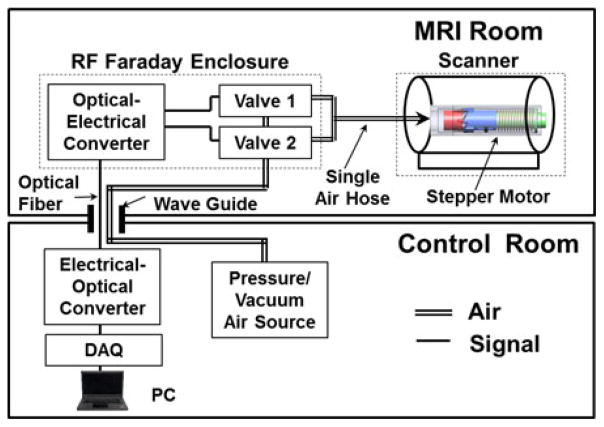
Fig. 1 shows a detailed description of the pneumatic actuation system. The system involves the pneumatic stepper motor, two MR-conditional piezoelectric valves, an optical-electrical converter, an electrical-optical converter, an air-driving source, a Data Acquisition (DAQ) card, and a PC. The air pressure and vacuum are provided via pneumatic lines from the air-driving source, which is located outside of the MRI scanner room. A vacuum is used to improve the pneumatic response of the driving system. The two piezoelectric valves (PS11111-B, HOERBIGER, Altenstadt, Germany) are placed inside an RF faraday enclosure in the MRI room, control flow in the pneumatic lines to the stepper motor. The valves are connected to the optical-electrical converter (CK1500, Carl’s Electronics, Oakland, CA, USA), which receives control signals through optical fibers via the MRI waveguide. These fibers are then connected to an electrical-optical converter linked with a PC in the scanner control room. A LabView program was written to generate stepper motor commands from the DAQ card (NI, 6009, Austin, Texas, USA) attached to the PC.
Fig. 1.
System diagram.
B. Motor Configuration
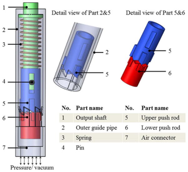
The motor design minimizes the number of moving parts to seven pieces. This simple configuration allows the motor to be 10 mm in diameter, move in defined steps of 60°, and does not require an encoder for positional control. The main components of the new pneumatic stepper motor are shown in Fig. 2.
Fig. 2.
CAD drawing of the stepper motor.
Fig. 2 illustrates the motor comprises seven major parts. The driving mechanism consists of the outer guide pipe and the push rods. When these pieces are in their home position, the upper and lower push rods are constrained by ridges on the inner surface of the outer guide pipe and the copper spring is preloaded to impart restoring force. The output shaft runs through the copper spring and is coupled to the upper push rod by the pin. Nonmagnetic materials were selected to fabricate the motor components to ensure its MRI compatibility and it can be seen in Table I.
TABLE I.
Motor Size and Number of Components
| Part | Material |
|---|---|
| Outer guide pipe | Ertalon |
| Spring | Copper |
| Pin | Ertalon |
| Output shaft | Glass Filled Nylon 66 |
| Upper push rod | Glass Filled Nylon 66 |
| Lower push rod | Glass Filled Nylon 66 |
C. Working Principle
The working principle is shown in Fig. 3 where the spring, pin, and output shaft have been removed to simplify the illustration of a single cycle.
Fig. 3.
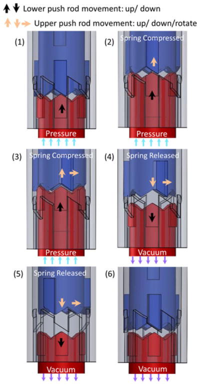
Working principle of the stepper motor. The upper push rod is blue, the outer guide pipe is lavender, and the lower push rod is red.
In steps 1 and 2, air from the pneumatic line presses upon the lower push rod. This pressure displaces the upper push rod and compresses the copper spring. The resultant force of the spring and the air pressure creates a horizontal force between the ridged teeth of the upper and lower push rods. This force causes the upper push rod try to rotate horizontally when it contacts the lower push rod (steps 2 and 3). At this moment, the upper push rod does not rotate because it is constrained by the outer guide pipe. As the air continues to apply force, the teeth on the upper push rod clear the internal ridges in the outer guide pipe. After step 3, the air pressure changes when a vacuum is applied. The reversal causes the push rods to drop quickly. As it falls, the upper push rod comes into contact with the teeth of the outer guide pipe (steps 4 and 5). The horizontal force between the upper push rod and the sloped surfaces of the teeth produce a torque that rotates the upper push rod. This motion continues until the teeth of the upper push rod interlock again with the ridges of the outer guide pipe, limiting the rotation to 60° (step 6). The vacuum makes the lower push rod drop quickly and improves the motor’s pneumatic response. The detailed operation sequence for one working period can be seen in Table II.
TABLE II.
Motor Operation Sequence
| Step | Motor status | Pneumatic sequence | Motor operation |
|---|---|---|---|
|
| |||
| 1 | Lower push rod starts to move upward | Pressure | 60° rotation |
| 2 | Lower push rod drives upper push rod upward | ||
| 3 | Lower push rod continues driving; upper push rod rotates | ||
|
| |||
| 4 | Lower push rod drops; upper push rod rotates and drops | Vacuum | |
| 5 | Lower push rod drops; upper push rod rotates and drops | ||
| 6 | Steady state | ||
It is worth noting that friction force is also generated between the upper push rod and outer guide pipe by the resultant force of the spring and air pressure. The friction force is relatively small compared with the spring force and air pressure and is neglected in the working principle analysis. Special attention has been made to the selection of the material for fabrication of the motor components to ensure its durability and reliable performance.
The working principle of the presented stepper motor is comparable to the stepper motor by Masamune et al. [14] with the difference in the relative position of each component inside the motor and the motor size. This paper, therefore, focuses on the theoretical analysis of the motor design, evaluation of its feasibility and manufacturability in a 10-mm small prototype, as well as testing its compatibility for working in a 3T MRI environment.
D. Theoretical Calculations
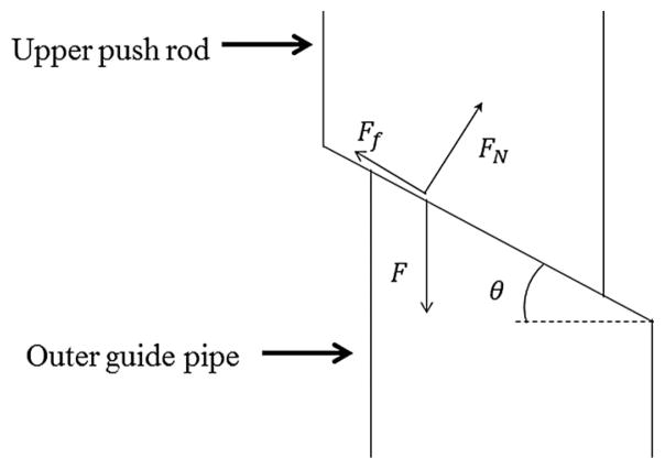
The driving force of the motor comes from the applied air pressure that pushes the rods and the restoring force of the spring. However, the arrangement of the gears ultimately controls the rotational motion. Since the tip angle of the stepper teeth has a large effect on the output torque, we evaluated the effect of spring stiffness and tooth tip angle of the upper push rod. Fig. 4 shows a force analysis at a single tooth.
Fig. 4.
Force analysis. Fn is the normal force exerted by the outer guide pipe and Ff is the friction force between the upper push rod and outer guide pipe. F is the spring force.
Fig. 4 shows the upper push rod and the outer guide pipe. We assume that the spring force will act on each tooth, and that it can be defined as F
| (1) |
where k is the spring stiffness and x denotes the distance the spring being compressed from its equilibrium position. The horizontal force Fh can be written as
| (2) |
where μ is the coefficient of friction for the material of the teeth. The driving torque can be written as
| (3) |
where n is the number of teeth and r is the radius of the upper push rod. The output torque with respect to the spring stiffness and tooth angle can be derived based on (3) as follows:
| (4) |
Therefore, the output torque is proportional to the value of spring stiffness from (4) and a larger spring stiffness is preferred if a higher torque is needed.
In this study, the relationship between the angular speed and tooth angle of the upper push rod has also been analyzed. According to the law of conservation of energy, the following equation applies:
| (5) |
where m is the mass of the upper push rod, M is the output shaft and the load mass, vv is the vertical speed, and vh is the horizontal speed. The left-hand side of the equation is the elastic potential energy, while the right part is the sum of the energy cost due to friction and kinetic energy. The energy lost by friction was assumed to be very small compared the kinetic energy from the motor output, and was, therefore, neglected. Then, we obtain the following equation:
| (6) |
Notably, the horizontal and vertical speeds have the following relationship:
| (7) |
Now, the horizontal velocity can be written as
| (8) |
and the angular speed of the upper push rod can be shown as follows:
| (9) |
By keeping the parameters of n, k, x, and r constant, the output torque and angular speed with respect to the angle θ and the coefficient of friction is shown in Fig. 5.
Fig. 5.
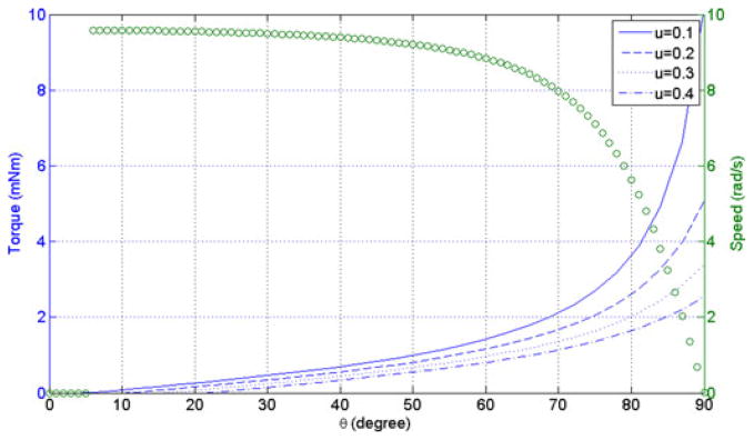
Output torque and angular speed (n = 3, k = 250 N/m, x = 0.6 mm, r = 2.4 mm, m = 10 g, M = 160 g). The blue curve is the torque and the green curve is the speed.
In Fig. 5, it was deduced that the torque and the speed are zero when the tooth angle is smaller than the self-locking angle, since the friction is larger than the kinematic output by the pressured air. For instance, output torque will be zero when tooth angle is smaller than 6° (μ = 0.1).
A larger tooth angle produces a higher output torque, just as a smaller friction coefficient does. There is an inverse relationship between angular speed and the tooth angle; i.e., the higher speeds correspond to small tooth angles, while the speed is close to zero is if the tooth angle is too large.
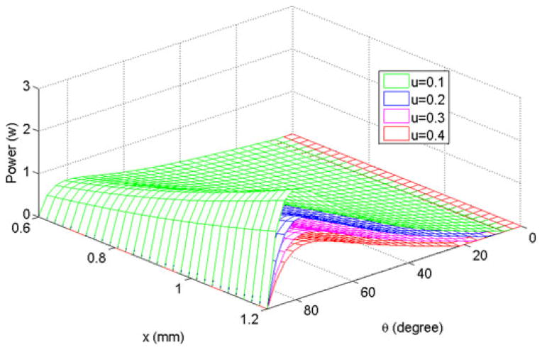
From the output torque and the angular speed chart (see Fig. 5), the output power was derived with respect to the tooth angle and the spring displacement (see Fig. 6).
Fig. 6.
Output power with respect to spring displacement (mm) and tooth angle (degrees).
Hence, a motor with a larger spring displacement will produce a higher output power. Based on the results from Figs. 5 and 6, it was concluded that a larger spring displacement, smaller friction coefficient, and optimized tooth angle would improve the motor’s power output.
III. Results and Discussion
A. Motor Dynamic Performance Evaluation
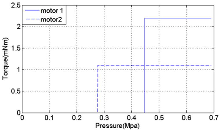
The output torque performances of the previous two MR-conditional pneumatic stepper motors are functions of the input air pressure. Due to the fact that air is compressible and does not act linearly, an active controller might be needed in order to achieve stable output torques. Our presented stepper motor was designed so that the output torque would be independent of air pressure levels. As aforementioned, the output torque of the presented pneumatic stepper motor is related only to the spring stiffness and the dimensions of the motor. It is the spring’s restoring force that rotates the upper push rod to generate an output torque. The air pressure only compresses the spring by moving the lower push rod. Therefore, the motor is activated when the compressed air exceeds a threshold pressure level, enabling it to maintain a constant speed and torque regardless of fluctuations in air pressure. Fig. 7 shows this unique characteristic when two different springs are installed in the stepper motor.
Fig. 7.
Output torque with respect to air pressure (spring stiffness k1 = 290 N/m and k2 = 250 N/m).
In Fig. 7, motor 1 begins to operate at an air pressure of 0.45 Mpa, while motor 2 starts at 0.28 Mpa. The output torque increased with spring stiffness. By choosing different values for spring stiffness, the output torque rating can be controlled. Also, the input air pressure does not increase or decrease the output torque when above the threshold pressure. Once the motor is activated, the output torque is stable and is not affected by the input air pressure. This is a design feature for a stable torque output without applying a complicated controller or torque sensor for the torque control. However, the constant torque characteristic may not be suitable for applications that require a variable output torque, such as the haptic master–slave systems [15].
In this study, the relationship between the output torque and the working speed was investigated as a second standard of the motor’s dynamic performance. Fig. 8 shows the measured the torque–speed relationship of the presented pneumatic motor. The maximum torque of the present motor is 2.4 mNm when the speed is 10 rpm.
Fig. 8.
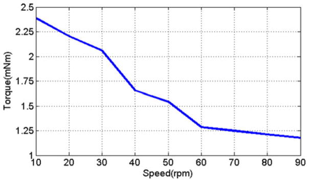
Output torque with respect to speed.
B. Comparative Study
A comparison of our motor and the existing two motors is listed in Table III in terms of size, number of components and some other functional performances.
TABLE III.
Comparison Among Nine Evaluation Standards of Different Pneumatic Stepper Motors
| Evaluation standards | S [10] | M [11] | P |
|---|---|---|---|
| Dimension [mm] | 70×20×25 85×30×30 |
~Φ30×35 | Φ10×60 |
| Volume [mm3] | 35000 76500 |
24728 | 4710 |
| Number of Components | ~25 | ~10 | 7 |
| Step size [deg] | 3.33 | 4.29 | 60 |
| Torque [mNm] | ~640 | ~150 | 2.4 |
| Max power [W] | 37 | ~0.1885 | 0.0025 |
| Speed [rpm] | 166.6 | 50 | 90 |
| Bidirectional/Unidirectional | Bidirectional | Bidirectional | Unidirectional |
| MR Safe/MR Conditional | MR Conditional | MR Safe | MR conditional |
Remark: S---Stoianovici’s, M---Masamune’s, and P---presented motor.
The presented motor is about 6% of the size of the motor designed by Stoianovici et al. and 19% of the size of the motor designed by Masamune et al., making it the smallest. Its miniature size could be extraordinarily helpful for integration into surgical devices, since compact motors can be useful in some applications where larger devices are not suitable, e.g., in handheld drilling instruments, robotic forceps and other end-effector designs. Furthermore, the presented motor consists of fewer components than the others. A motor consisting of a large number of components increases its complexity, possibly shortening the working life of the device. Our stepper motor design can avoid these problems by using fewer components.
However, the other performances of the presented stepper motor, such as the torque, power, and step size, are weaker than the existing two stepper motors by Stoianvoci et al. and Masamune et al., which could limit its applications in where requires high power or accurate positional resolution.
C. Conditional Evaluation
To evaluate the MR compatibility and safety of the presented pneumatic stepper motor, experiments were conducted in a GE 3T MRI scanner to quantify 1) the MR image artifact produced by the motor and 2) the SNR of the images when the stepper motor and electronic devices were in operation [16].
In this study, the ASTM standard F2119 was chosen to define the image artifact generate by the stepper motor [17]. The artifact width is measured from the subject body to the artifact fringe where there is a 30% change of pixel intensity relative to the reference image where the subject is absent. The SNR test was conducted by putting the stepper motor in a container of CuSO4 solution at the isocenter of the scanner. The turbo spin echo sequence was adopted to obtain the MR images. Fig. 9 depicts the image artifact generated by the stepper motor.
Fig. 9.
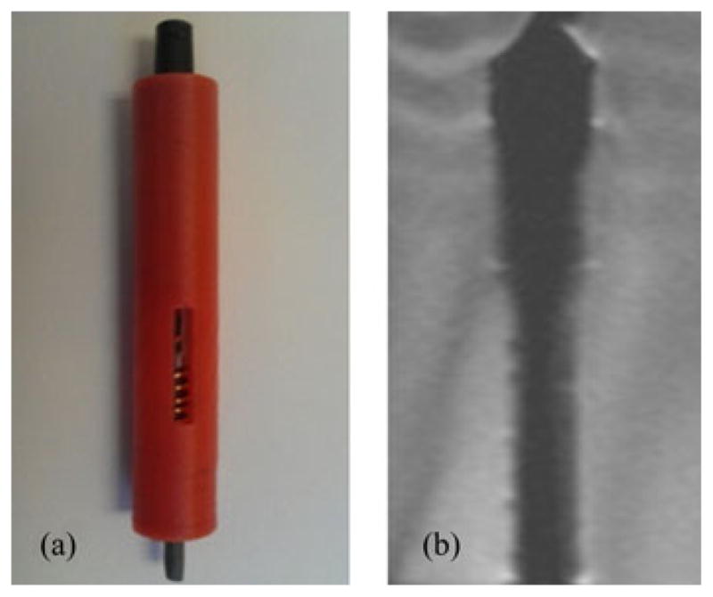
MRI artifact and SNR reduction tests. (a) Motor image. (b) MR image of the motor.
There are several standards available in the literature to characterize the effect of a device on the MRI, such as system safety, device function, and MR image quality [18], [19]. In this paper, the characterization methods were limited to evaluation of the MR image quality by calculating the SNR and maximum image artifact width. Fig. 9(a) and (b) shows the artifact generated by the stepper motor with the maximum artifact width of 3-mm outside the motor body. SNR was quantified using the following equation:
| (10) |
where pcenter is the mean intensity value within the 40 ×40 pixel region located at the image center, and SDcorner is the standard deviation of the intensity value within the 40 × 40 pixel region at the image corner [7]. Fig. 10 shows the SNR generated by the stepper motor under three conditions. The maximum SNR reduction is 2.49% occurs when the motor is off and inside the MRI isocenter, ensuring the quality of MR images.
Fig. 10.
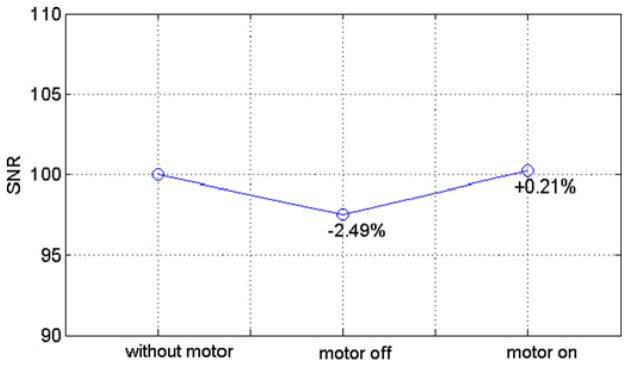
SNR reduction test obtained when motor is off, on inside the MRI isocenter and when outside the scanner.
IV. Conclusion
A new type of MR-conditional pneumatic stepper motor was presented. This motor rotates in angular steps of 60° with a maximum torque of 2.4 mNm. Compared to the existing pneumatic motors, the presented motor is smaller in size, less complex, demonstrates nonpressure dependent output, and exhibits impressive SNR. The motor output depends solely on the spring stiffness and the dimensional parameters. Thus, it can provide stable output without the use of complicated control methods. The motor design can be altered for a larger output torque by increasing the spring stiffness without changing its size. The major feature of the presented motor is its small size and fewer components, making it the smallest MR-conditional pneumatic stepper motor currently in existence to the best of the author’s knowledge. Experimentally, a maximum artifact width of 3 mm was produced in MR images and an SNR of 2.49% was recorded. This motor provides an alternative method for precise actuation in MRI-conditional applications.
Future work will focus on the study of improving the stepper motor dynamic performances, such as torque and power, as well as further evaluation of the effect of the present motor on the MRI based on different evaluation standards [18], [19].
Biographies

Yue Chen received the B.S. degree (with first class Hons.) in vehicle engineering from Hunan University, Changsha, China, in 2010, and the M.Phil. degree in mechanical engineering from The Hong Kong Polytechnic University, Hong Kong, China, in 2013. He is currently working toward the Ph.D. degree at the College of Engineering, The University of Georgia, Athens, GA, USA.
His research interests include medical robotics, image-guided surgery, and MRI.

Christopher D. Mershon was born in Misawa, Japan, on June 9, 1990. He is currently working toward the B.S. degree in biological engineering (biomedical emphasis) at The University of Georgia, Athens, GA, USA.
His research interests include MRI-compatible robotics, wireless power transfer, and low-cost prostate cancer screening.

Zion Tsz Ho Tse received the B.Eng. degree (first class Hons.) in mechanical engineering from the University of Hong Kong, Hong Kong, China, in 2006, and the Ph.D. degree in mechatronics in medicine from Imperial College London, London, U.K., in 2009.
He is currently an Assistant Professor with the College of Engineering at The University of Georgia (UGA), Athens, GA, USA. Before joining UGA in 2012, he was a Research Fellow at Harvard Medical School and Brigham and Women’s Hospital. His current research interests include medical robotics, computer-aided surgery, and magnetic resonance imaging.
Footnotes
Color versions of one or more of the figures in this paper are available online at http://ieeexplore.ieee.org.
Contributor Information
Yue Chen, Email: ychen@uga.edu.
Christopher D. Mershon, Email: cmershon@uga.edu.
Zion Tsz Ho Tse, Email: ziontse@uga.edu.
References
- 1.Potkin BN, Bartorelli AL, Gessert JM, Neville RF, Almagor Y, Roberts WC, Leon MB. Coronary-artery imaging with intravascular high-frequency ultrasound. Circulation. 1990 May;81:1575–1585. doi: 10.1161/01.cir.81.5.1575. [DOI] [PubMed] [Google Scholar]
- 2.Tops LF, Bax JJ, Zeppenfeld K, Jongbloed MRM, Lamb HI, van der Wall EE, Schalij MJ. Fusion of multislice computed tomography imaging with three-dimensional electroanatomic mapping to guide radiofrequency catheter ablation procedures. Heart Rhythm. 2005 Oct;2:1076–1081. doi: 10.1016/j.hrthm.2005.07.019. [DOI] [PubMed] [Google Scholar]
- 3.McRobbie DW, Moore EA, Graves MJ, Prince MR. MRI From Picture to Proton. Cambridge, U.K: Cambridge Univ. Press; 2006. [Google Scholar]
- 4.Han BK, Schnall MD, Orel SG, Rosen M. Outcome of MRI-guided breast biopsy. Amer J Roentgenol. 2008 Dec;191:1798–1804. doi: 10.2214/AJR.07.2827. [DOI] [PubMed] [Google Scholar]
- 5.Tse ZTH, Elhawary H, Rea M, Davies B, Young I, Lamperth M. Haptic needle unit for MR-guided biopsy and its control. IEEE/ASME Trans Mechatronics. 2012 Feb;17(1):183–187. [Google Scholar]
- 6.Chinzei K, Miller K. Towards MRI guided surgical manipulator. Med Sci Monit. 2001 Jan;7:153–163. [PubMed] [Google Scholar]
- 7.Chinzei K, Kikinis R, Jolesz FA. MR compatibility of mechatronic devices: Design criteria. Proc. Med. Image Comput. Comput.-Assisted Intervention; Jan. 1999; pp. 1020–1030. [Google Scholar]
- 8.ASTM. F2503–05 Standard Practice for Marking Medical Devices and Other Items for Safety in the Magnetic Resonance Environment. 2005 doi: 10.6009/jjrt.2018_JSRT_74.7.739. [Online]. Available: http://www.astm.org/Standards/F2503.htm. [DOI] [PubMed]
- 9.FDA. A Primer on Medical Device Interactions with Magnetic Resonance Imaging Systems. 1997 [Online]. Available: http://www.fda.gov/medicaldevices/deviceregulationandguidance/guidancedocuments/ucm107721.htm.
- 10.Stoianovici D, Patriciu A, Petrisor D, Mazilu D, Kavoussi L. A new type of motor: Pneumatic step motor. IEEE/ASME Trans Mechatronics. 2007 Feb;12(1):98–106. doi: 10.1109/TMECH.2006.886258. [DOI] [PMC free article] [PubMed] [Google Scholar]
- 11.Sajima H, Kamiuchi H, Kuwana K, Dohi T, Masamune K. MR-safe pneumatic rotation stepping actuator. J Robot Mechatronics. 2012 Jul;24:820–827. [Google Scholar]
- 12.Sato I, Funakubo A, Dohi T, Masamune K. EMC design of MR-compatible needle guiding a manipulator for 0.2T open-type MRI. Int J Comput Assisted Radiol Surg. 2008 Jun;3:304–305. [Google Scholar]
- 13.Fischer GS. PhD dissertation. Worcester Polytech. Inst., The Johns Hopkins Univ; Baltimore, MD, USA: 2008. Enabling technologies for MRI guided interventional procedures. [Google Scholar]
- 14.Masamune K, Dohi T, Matsumiya K, Utsugida T. PCT/JP2008/069737. Stepping actuator. 2009 May 7;
- 15.Coles TR, Meglan D, John NW. The role of haptics in medical training simulators: A survey of the state of the art. IEEE Trans Haptics. 2011 Jan-Feb;4(1):51–66. doi: 10.1109/TOH.2010.19. [DOI] [PubMed] [Google Scholar]
- 16.Tse ZTH, Elhawary H, Zivanovic A, Rea M, Paley M, Bydder G, Davies BL, Young I, Lamperth MU. A 3-DOF MR-compatible device for magic angle related in vivo experiments. IEEE/ASME Trans Mechatronics. 2008 Jun;13(3):316–324. [Google Scholar]
- 17.ASTM. F2119 Standard Test Method for Evaluation of MR Image Artifacts from Passive Implants. 2013 [Online]. Available: http://www.astm.org/Standards/F2119.htm.
- 18.Yu N, Gassert R, Riener R. Mutual interferences and design principles for mechatronic devices in magnetic resonance imaging. Int J Comput Assisted Radiol Surg. 2011;6:473–488. doi: 10.1007/s11548-010-0528-2. [DOI] [PubMed] [Google Scholar]
- 19.Stoianovici D. Multi-imager compatible actuation principles in surgical robotics. Int J Med Robot Comput Assisted Surg. 2005;1:86–100. doi: 10.1002/rcs.19. [DOI] [PMC free article] [PubMed] [Google Scholar]


